| Issue |
A&A
Volume 590, June 2016
|
|
|---|---|---|
| Article Number | A88 | |
| Number of page(s) | 31 | |
| Section | Stellar atmospheres | |
| DOI | https://doi.org/10.1051/0004-6361/201527718 | |
| Published online | 18 May 2016 | |
Atmospheric NLTE models for the spectroscopic analysis of blue stars with winds
III. X-ray emission from wind-embedded shocks
1 LMU Munich, Universitätssternwarte, Scheinerstr. 1, 81679 München, Germany
e-mail: This email address is being protected from spambots. You need JavaScript enabled to view it.
2 Centro de Astrobiología, CSIC-INTA, Ctra. Torrejón a Ajalvir km.4, 28850 Madrid, Spain
3 Instituut voor Sterrenkunde, KU Leuven, Celestijnenlaan 200D, 3001 Leuven, Belgium
Received: 9 November 2015
Accepted: 1 March 2016
Abstract
Context. Extreme ultraviolet (EUV) and X-ray radiation emitted from wind-embedded shocks in hot, massive stars can affect the ionization balance in their outer atmospheres and can be the mechanism responsible for producing highly ionized atomic species detected in stellar wind UV spectra.
Aims. To allow for these processes in the context of spectral analysis, we have implemented the emission from wind-embedded shocks and related physics into our unified, NLTE model atmosphere/spectrum synthesis code FASTWIND.
Methods. The shock structure and corresponding emission is calculated as a function of user-supplied parameters (volume filling factor, radial stratification of shock strength, and radial onset of emission). We account for a temperature and density stratification inside the postshock cooling zones, calculated for radiative and adiabatic cooling in the inner and outer wind, respectively. The high-energy absorption of the cool wind is considered by adding important K-shell opacities, and corresponding Auger ionization rates have been included in the NLTE network. To test our implementation and to check the resulting effects, we calculated a comprehensive model grid with a variety of X-ray emission parameters.
Results. We tested and verified our implementation carefully against corresponding results from various alternative model atmosphere codes, and studied the effects from shock emission for important ions from He, C, N, O, Si, and P. Surprisingly, dielectronic recombination turned out to play an essential role for the ionization balance of O iv/O v (particularly in dwarfs with Teff~ 45 000 K). Finally, we investigated the frequency dependence and radial behavior of the mass absorption coefficient, κν(r), which is important in the context of X-ray line formation in massive star winds.
Conclusions. In almost all of the cases considered, direct ionization is of major influence because of the enhanced EUV radiation field, and Auger ionization only affects N vi and O vi significantly. The approximation of a radially constant κν is justified for r ≳ 1.2 R∗ and λ ≲ 18 Å and also for many models at longer wavelengths. To estimate the actual value of this quantity, however, the He ii opacities need to be calculated from detailed NLTE modeling, at least for wavelengths longer than 18 to 20 Å, and information on the individual CNO abundances has to be present.
Key words: methods: numerical / stars: atmospheres / stars: early-type / stars: winds, outflows / X-rays: stars
© ESO, 2016
1. Introduction
Most of our knowledge about the physical parameters of hot stars has been inferred by means of quantitative spectroscopy, i.e., the analysis of stellar spectra based on atmospheric models. The computation of such models is very challenging, mostly because of the intense radiation fields of hot stars leading to various effects that are absent in the atmospheres of cooler stars, such as the requirement for a kinetic equilibrium description (also simply called NLTE = non-LTE) and the presence of strong, radiation-driven winds.
In recent decades, a number of numerical codes have been developed that enable the calculation of synthetic profiles/spectral energy distributions (SEDs) from such hot stars. Apart from plane-parallel, hydrostatic codes, which can be used to analyze those atmospheres that are less affected by the wind (e.g., tlusty, Hubeny 1998; Detail/Surface, Giddings 1981; Butler & Giddings 1985), all of these codes apply the concept of unified (or global) model atmospheres (Gabler et al. 1989), which aims at a consistent treatment of both photosphere and wind, i.e., including (steady-state) mass loss and velocity fields. Examples of such codes are CMFGEN (Hillier & Miller 1998), PHOENIX (Hauschildt 1992), PoWR (Gräfener et al. 2002), WM-basic (Pauldrach et al. 2001), and FASTWIND (Puls et al. 2005; Rivero González et al. 2012a)1. A brief comparison of these different codes can be found in Puls (2009).
In the present paper, we report on recent progress to improve the capabilities of FASTWIND, which is widely used to analyze the optical spectra of hot massive stars (e.g., in the context of the VLT-flames survey of massive stars, Evans et al. 2008; and the VLT-flames Tarantula Survey, Evans et al. 2011). One of the most challenging aspects of these surveys was the analysis of the atmospheric nitrogen content, which is processed in the stellar core by the CNO cycle and transported to the outer layers by rotational mixing, to derive stringent constraints for up-to-date evolutionary calculations. Though the optical nitrogen analysis of B-stars (dwarfs and supergiants with not too dense winds) could still be performed by a hydrostatic code (in this case TLUSTY, e.g., Hunter et al. 2007, 2008), a similar analysis of hotter stars with denser winds required the application of unified model atmospheres, due to the wind impact on the strategic nitrogen lines (Rivero González et al. 2011, 2012a; Martins et al. 2012). Moreover, because of the complexity of the involved processes, the precision of the derived nitrogen abundances2 is still questionable. To independently check this precision and to obtain further constraints, a parallel investigation of the carbon (and oxygen) abundances is urgently needed, since at least the N/C abundance ratio as a function of N/O might be predicted almost independently from the specific evolutionary scenario (Przybilla et al. 2010), and thus allows individually derived spectroscopic abundances to be tested (see also Martins et al. 2015a).
As shown by Martins & Hillier (2012), however, the optical diagnostics of carbon in O stars is even more complex than the nitrogen analysis, since specific, important levels are pumped by a variety of UV resonance lines. Thus, an adequate treatment of UV lines is inevitable, both for the optical diagnostics and to constrain the results by an additional analysis of carbon lines located in the UV. If at least part of these lines are formed in the wind, the inclusion of X-ray and extreme ultraviolet (EUV) emission from wind-embedded shocks turns out to be essential (see below); this is the main reason (though not the only one) for our current update of FASTWIND. Other codes such as CMFGEN, PoWR, and WM-basic already include these processes, thus enabling the modeling of the UV (e.g., Pauldrach et al. 2001; Crowther et al. 2002; Hamann & Oskinova 2012) and the analysis of carbon (plus nitrogen and oxygen, e.g., Bouret et al. 2012; Martins et al. 2015a,b for the case of Galactic O stars).
X-ray emission from hot stars has been measured at soft (0.1 to ≳2 keV) and harder energies, either at low resolution in the form of a quasi-continuum, or at high resolution allowing the investigation of individual lines (e.g., Oskinova et al. 2006; Owocki & Cohen 2006; Hervé et al. 2013; Leutenegger et al. 2013b; Cohen et al. 2014b; Rauw et al. 2015). The first X-ray satellite observatory, EINSTEIN, has already revealed that O stars are soft X-ray sources (Harnden et al. 1979; Seward et al. 1979), and Cassinelli & Swank (1983) were the first to show that the observed X-ray emission is due to thermal emission, dominated by lines. Follow-up investigations, particularly by ROSAT, have subsequently allowed us to quantify X-ray properties for many OB stars (see Kudritzki & Puls 2000 and references therein). Accounting also for more recent work based on Chandra and XMM-Newton, it was found that the intrinsic X-ray emission of “normal” O stars is highly constant w.r.t. time (e.g., Nazé et al. 2013), and that the level of X-ray emission is strictly related to basic stellar and wind parameters, e.g., Lx/Lbol ≈ 10-7 for O stars (Chlebowski et al. 1989; Sana et al. 2006; Nazé et al. 2011).
Such X-ray emission is widely believed to originate from wind-embedded shocks, and to be related to the line-driven instability (LDI; e.g., Lucy & Solomon 1970; Owocki & Rybicki 1984; Owocki et al. 1988; Owocki 1994; Feldmeier 1995). In terms of a stationary description, a simple model (e.g., Hillier et al. 1993; Cassinelli et al. 1994) assumes randomly distributed shocks above a minimum radius, Rmin≈ 1.5 R∗. This is consistent with X-ray line diagnostics ( e.g., Leutenegger et al. 2013b; see also Rauw et al. 2015) in which the hot shocked gas (with temperatures of a few million Kelvin and a volume filling factor on the order of 10-3 to a few 10-2) is collisionally ionized/excited and emits X-ray/EUV photons due to spontaneous decay, radiative recombinations, and bremsstrahlung. The ambient, cool wind then reabsorbs part of the emission, mostly via K-shell processes. The strength of this wind absorption has a strong frequency dependence. For energies beyond 0.5 keV (e.g., the Chandra bandpass), the absorption is very modest (e.g., Cohen et al. 2011), whilst for softer X-rays and the EUV regime the absorption is significant, even for winds with low mass-loss rates (e.g., Cohen et al. 1996). In the latter case, only a small fraction of the produced radiation actually leaves the wind.
This simple model, sometimes extended to account for the post-shock cooling zones of radiative and adiabatic shocks (see Feldmeier et al. 1997a; but also Owocki et al. 2013), is used in the previously mentioned NLTE codes, particularly to account for the influence of X-ray/EUV emission on the photoionization rates.
Since the detection of high ionization stages in stellar wind UV spectra, such as O vi, S vi, and N v (Snow & Morton 1976; Lamers & Morton 1976; Lamers & Rogerson 1978), that cannot be produced in a cool wind (thus, denoted “superionization”), the responsible mechanism was, and partly still is, subject to debate. Because the X-ray and associated EUV luminosity emitted by the shocks is quite strong, it can severely affect the degree of ionization of highly ionized species by Auger ionization (Macfarlane et al. 1993) and even more by direct ionization in the EUV (Pauldrach et al. 1994, 2001). A first systematic investigation of these effects on the complete FUV spectrum, as a function of stellar parameters, mass loss, and X-ray luminosity was performed by Garcia (2005).
In this paper, we present our approach for implementing wind-embedded shocks into FASTWIND to allow for further progress as outlined above, and report on corresponding tests and first results. In Sect. 2, our model for the X-ray emission and cool-wind absorption is described along with coupling to the equations of statistical equilibrium. In Sect. 3 we present our model grid, which constitutes the basis of our further discussion. Section 4 provides some basic tests and Sect. 5 presents first results. In particular, we discuss how the ionization fractions of specific, important ions are affected by X-ray emission, and how these fractions change when the description of the emission (filling factors and shock temperatures) is varied (Sect. 5.1). We compare with results from other studies (Sect. 5.1.4) and investigate the impact of Auger compared to direct ionization (Sect. 5.2). We discuss the impact of dielectronic recombination in O v in Sect. 5.3, and comment on the radial behavior of the mass absorption coefficient (as a function of wavelength), which is an important issue for X-ray line diagnostics (Sect. 5.4). Finally, we present our summary and conclusions in Sect. 6.
2. Implementation of X-ray emission and absorption in FASTWIND
Our implementation of the X-ray emission and absorption from wind-embedded shocks closely follows the implementation by Pauldrach et al. (2001) for WM-basic (see also Pauldrach et al. 1994), which in turn is based on the model for shock cooling zones developed by Feldmeier et al. (1997a, see Sect.1. Except for the description of the cooling zones, this implementation is similar to the approaches by Hillier & Miller (1998, CMFGEN, but using a different definition of the filling factor, see below), Oskinova et al. (2006, POWR), and Krtička & Kubát (2009, hereafter KK09). In the following, we summarize our approach.
2.1. X-ray emission
Following Feldmeier et al. (1997a), the energy (per unit of volume, time, and frequency), emitted by the hot gas into the full solid angle 4π can be written as3 (1)where np(r) and ne(r) are the proton and electron density of the (quasi-)stationary, cool (pre-shock) wind, Ts(r) is the shock temperature, and fX(r) the filling factor related to the (volume) fraction of the X-ray emitting material4. Indeed, this definition differs from the formulation suggested by Hillier et al. (1993, their Eq. (2)), since we include here their factor 16 into fX (accounting for the density jump in a strong adiabatic shock). This definition is then identical with that used in WM-basic, POWR (presumably5), and by KK09, whilst the relation to the filling factor used in CMFGEN, es, is given by
  (2)In principle, Λν is the frequency-dependent volume emission coefficient (“cooling function”) per proton and electron, calculated here using the Raymond-Smith code (Raymond & Smith 1977, see also Smith et al. 2001), with abundances from the FASTWIND input, and neglecting the weak dependence on ne. We evaluate the cooling function at a fixed electron density, ne = 1010 cm-3 (as also done, e.g., by Hillier et al. 1993 and Feldmeier et al. 1997a), and have convinced ourselves of the validity of this approximation. We note here that the only spectral features with a significant dependence on electron density are the forbidden and intercombination lines of He-like emission complexes, and even there (i) the density dependence is swamped by the dependence on UV photoexcitation; and (ii) in any case the flux of the forbidden plus intercombination line complex (f+i lines are very closely spaced) is conserved.
In contrast with the assumption of a hot plasma with a fixed postshock temperature and density (as adopted in some of the above codes), in our implementation we account for a temperature and density stratification in the postshock cooling zones, and we note that the decreasing temperature and increasing density should significantly contribute to the shape of the emitted X-ray spectrum (Krolik & Raymond 1985). To this end, we adopt the structure provided by Feldmeier et al. (1997a), and integrate the emitted energy (Eq. (1)) over the cooling zone,  (3)with
  (4)where r is the position of the shock front and Lc the spatial extent of the cooling zone. In this formulation, the “+” sign corresponds to a reverse shock, and the “−” sign to a forward shock. The functions f and g provide the normalized density and temperature stratification inside the cooling zone, and are calculated following Feldmeier et al. (1997a), accounting for radiative and adiabatic cooling in the inner and outer wind, respectively (see Sect. 2.3). We integrate over 1,000 subgrid points within Lc, finding identical results for both f(r) and g(r) as well as for
  , compared to the original work (Figs. 1 and 7; 2 and 8 in Feldmeier et al. 1997a). By setting f = g = 1, we are able to return to nonstratified, isothermal shocks.
In our implementation, the (integrated) cooling function and, thus, the emissivity is evaluated in the interval between 1 eV and 2.5 keV for a bin-size of 2.5 eV. These emissivities are then resampled onto our coarser frequency grid as used in FASTWIND in such a way as to preserve  dν in each of the coarser subintervals, thus enabling correct photo integrals for the rate equations.
The immediate postshock temperature, Ts(r), entering Eq. (4), follows from the Rankine-Hugoniot equations ![Mathematical equation: \begin{equation} \label{shock_temp} \Tshock(r) = \frac{3}{16}\frac{\mu m_{\textnormal{H}}}{k_{\rm B}}\ \left(u^{2}+ \left[\frac{14}{5}\adiabsound^{2}\ \left(1 - \frac{3}{14}\ \frac{\adiabsound^{2}}{u^{2}}\right)\right]\right) , \end{equation}](/articles/aa/full_html/2016/06/aa27718-15/aa27718-15-eq32.png) (5)where u is the jump velocity, μ the mean atomic weight, and as the adiabatic upstream sound speed. For simplicity, we calculate the shock temperature from a more approximate expression, neglecting the term in the square bracket, i.e., assuming the strong shock scenario (
(5)where u is the jump velocity, μ the mean atomic weight, and as the adiabatic upstream sound speed. For simplicity, we calculate the shock temperature from a more approximate expression, neglecting the term in the square bracket, i.e., assuming the strong shock scenario ( ),
),  (6)To derive Ts, we thus need to specify the jump velocity u, adopted in accordance with Pauldrach et al. (1994, their Eq. (3)) as
 ![Mathematical equation: \begin{equation} \label{jump_velo} u(r) = u_{\infty} \biggl[\frac{v(r)}{\vinf}\biggr]^{\gamma_{\rm x}} , \end{equation}](/articles/aa/full_html/2016/06/aa27718-15/aa27718-15-eq37.png) (7)where u∞ is the maximum jump speed, which in our implementation is an input parameter (on the order of 300 to 600 km s-1, corresponding to a maximum shock temperature,
(7)where u∞ is the maximum jump speed, which in our implementation is an input parameter (on the order of 300 to 600 km s-1, corresponding to a maximum shock temperature,  to 5 × 10⁶ K for O stars), together with the exponent γx (in the typical range 0.5...2) that couples the jump velocity with the outflow velocity, controlling the shock strength. A parameterization such as Eq. (7) is motivated primarily by the observed so-called “black troughs” in UV P-Cygni profiles. Namely, when modeled using a steady-state wind6, such black troughs can only be reproduced when assuming a velocity dispersion that increases in parallel with the outflow velocity, which is interpreted as a typical signature of wind structure (e.g., Groenewegen & Lamers 1989; Haser 1995). However, Eq. (7) only represents one possible implementation of the radial distribution of wind-shock strengths, and ultimately the user is responsible for her/his choice of parameterization (see also discussion in Sect. 6).
The last required parameter is the onset radius of the X-ray emission, Rmin. This value is controlled by two input parameters,  and a factor mx (the latter in accordance with Pauldrach et al. 1994). From these values, Rmin is calculated via
  (8)For all radii r>Rmin, the X-ray emission is switched on. Rmin values from 1.1 to 1.5 R∗ are, e.g., supported by Pauldrach et al. (1994) from their analysis of the O vi resonance lines. Hillier et al. (1993) analyzed the sensitivity to Rmin, pointing to indistinguishable X-ray flux differences when the onset is varied between 1.5 and 2 R∗. Recent analyses of X-ray line emission from hot star winds also point to values around 1.5 R∗ (e.g., Leutenegger et al. 2006; Oskinova et al. 2006; Hervé et al. 2013; Cohen et al. 2014b), although Rauw et al. (2015) derived a value of 1.2 R∗ for the wind of λ Cep.
2.2. X-ray absorption and Auger ionization
Besides the X-ray emission, we need to compute the absorption by the cold background wind; the optical depths inside the shocked plasma are so low that absorption can be neglected there.
In FASTWIND, the cool wind opacity is computed in NLTE. To include X-ray absorption requires that we (i) extend the frequency grid and coupled quantities (standard7 opacities and emissivities, radiative transfer) into the X-ray domain (up to 2.5 keV ≈ 5 Å); and (ii) compute the additional absorption by inner shell electrons, leading to, for example, Auger ionization. So far, we included only K-shell absorption for light elements using data from Daltabuit & Cox (1972). L- and M-shell processes for heavy elements, which are also present in the considered energy range, have not been incorporated until now, but would only lead to marginal effects, as test calculations by means of WM-basic have shown.
We checked that the K-shell opacities by Daltabuit & Cox (1972) are very similar (with typical differences less than 5%) to the alternative and more modern dataset from Verner & Yakovlev (1995), at least in the considered energy range (actually, even until 3.1 keV)8.
While the provided dataset includes K-shell opacities from the elements C, N, O, Ne, Mg, Si, and S, the last element (S) has threshold energies beyond our maximum energy, 2.5 keV; hence, K-shell absorption and Auger ionization for this element is not considered in our model.
After calculating the radiative transfer in the X-ray regime, accounting for standard and K-shell opacities and standard and X-ray emissivities, we are able to calculate the corresponding photo rates required to consider Auger ionization in our NLTE treatment. Here, we do not only include the transition between ions separated by a charge difference of two (such as, e.g., the ionization from O iv to O vi), but we follow Kaastra & Mewe (1993) who stressed the importance of cascade ionization processes, enabling a sometimes quite extended range of final ionization stages. For example, the branching ratio for O iv to O v vs. O iv to O vi is quoted as 96:9904, whilst the branching ratios for Si iii to Si iv/Si v/Si vi are 3:775:9222; i.e., here the major Auger-ionization occurs for the process III to VI. In our implementation of Auger ionization, we accounted for all possible branching ratios following the data provided by Kaastra & Mewe.
Finally, we reiterate that in addition to such inner shell absorption/Auger ionization processes, direct ionization due to X-rays/enhanced EUV radiation (e.g., of O v and O vi) is essential and automatically included in our FASTWIND modeling. The impact of direct vs. Auger ionization is compared in Sect. 5.2.
2.3. Radiative and adiabatic cooling
As pointed out in Sect. 2.1, the shock cooling zones are considered to be dominated by either radiative or adiabatic cooling, depending on the location of the shock front. More specifically, the transition between the two cooling regimes is obtained from the ratio between the radiative cooling time, tc, i.e., the time required by the shocked matter to return to the ambient wind temperature, and the flow time, tf, the time for the material to cross Lc (expressions for these quantities can be found in Feldmeier et al. 1997a; but see also Hillier et al. 1993). In the inner part of the wind, the cooling time is shorter than the flow time and the shocks are approximated as radiative. Further out in the wind, at low densities, tc ≫ tf, and the cooling is dominated by adiabatic expansion (see also Simon & Axford 1966). In our approach, we switch from one treatment to the other when a unity ratio is reached, where tc/tf ∝ Ts(r)1.5rv2(r) /Ṁ. For typical O supergiants and shock temperatures, the transition occurs in the outermost wind beyond r> 50 R∗, whilst for O dwarfs the transition can occur at much lower radii, r> 2.5 R∗ or even lower for weak-winded stars.
Basically, each cooling zone is bounded by a reverse shock at the starward side and a forward shock at the outer side. Time-dependent wind simulations (e.g., Feldmeier 1995) show that in the radiative case the forward shock is much weaker than the reverse shock and, thus, is neglected in our model. In the adiabatic case, we keep both the reverse and forward shock and, for lack of better knowledge, assume equal Ts for both components (Θ = 1 in the nomenclature by Feldmeier et al. 1997a), and an equal contribution of 50% to the total emission.
3. Model grid
In this section, we describe the model grid used in most of the following work. To allow for a grid of theoretical models that enables us to investigate different regimes of X-ray emission for different stellar types and to perform meaningful tests, we use the same grid as presented by Pauldrach et al. (2001, their Table 5) for discussing the predictions of their (improved) WM-basic code9. Moreover, this grid has already been used by Puls et al. (2005) to compare the results from an earlier version of FASTWIND with the WM-basic code.
For convenience, we present the stellar and wind parameters of this grid in Table 1. For all models, the velocity field exponent has been set to β = 0.9. The FASTWIND and WM-basic models display a certain difference in the velocity field10.
All entries shown in Table 1 refer to homogeneous winds, however, for specific tests (detailed when required) we have calculated microclumped models as well (i.e., assuming optically thin clumps). Although clumping is not considered in our standard model grid, a (micro-)clumped wind could be roughly compared to our unclumped models as long as the mass-loss rate of the clumped model corresponds to the mass-loss rate of the unclumped model divided by the square root of the clumping factor. We note, however, that the K-shell opacities scale linearly with density, i.e., ∝Ṁ, and as such are not affected by microclumping.
Stellar and wind parameters of our grid models with homogeneous winds, following Pauldrach et al. (2001).
All models in the present work were calculated by means of the most recent version (as described in Rivero González et al. 2012a) of the NLTE atmosphere/spectrum synthesis code FASTWIND, including the X-ray emission from wind-embedded shocks as outlined in Sect. 2. We further point out that FASTWIND calculates the temperature structure of the photosphere and cold wind from the electron thermal balance (Kubát et al. 1999), and its major influence in the wind is via recombination rates. In most cases, this temperature structure is only slightly or moderately affected by X-ray/EUV emission, since the overall ionization balance with respect to main ionization stages11 remains rather unaffected (see Sect. 5), except for extreme X-ray emission parameters. In any case, the change of the net ionization rates for ions with edges in the soft X-ray/EUV regime is dominated by modified photo rates (direct and Auger ionization), whilst the changes of recombination rates (due to a modified temperature) are of second order.
In FASTWIND, we used detailed model atoms for H, He, and N (described by Puls et al. 2005; Rivero González et al. 2012a) together with C, O, P (from the WM-basic data base, see Pauldrach et al. 2001) and Si (see Trundle et al. 2004) as “explicit” elements. Most of the other elements up to Zn are treated as background elements. For a description of FASTWIND and the philosophy of explicit and background elements, see Puls et al. (2005) and Rivero González et al. (2012a).
In brief, explicit elements are those used as diagnostic tools and treated with high precision by detailed atomic models and by means of comoving frame transport for all line transitions. The background elements (i.e., the rest) are needed only for the line-blocking/blanketing calculations, and are treated in a more approximate way, using parameterized ionization cross sections following Seaton (1958) and a comoving frame transfer only for the most important lines, whilst the weaker ones are calculated by means of the Sobolev approximation. We employed solar abundances from Asplund et al. (2009), together with a helium abundance, by number, NHe/NH = 0.1.
Besides the atmospheric and wind parameters shown in Table 1, our model of X-ray emission requires the following additional input parameters: fX, u∞, γx, mx, and , as described in the previous section.
For most of the models discussed in Sect. 5, we calculated, per entry in Table 1, 9 different sets of X-ray emission: fX (adopted as spatially constant) was set to 0.01, 0.03, and 0.05, whilst the maximum shock velocity, u∞, was independently set to 265, 460, and 590 km s-1, corresponding to maximum shock temperatures of 1, 3, and 5 × 10⁶ K.
For all models, we used γx = 1.0,  , and mx = 20. This corresponds to an effective onset of X-rays, Rmin, between 1.2 and 1.5 R∗, or 0.1 and 0.2 v∞, respectively (see Table 1, last column). Thus, our current grid comprises 9 times 11 = 99 models, and has enough resolution to compare this grid with previous results from other codes and to understand the impact of the X-ray radiation onto the ionization fractions of various elements.
4. Tests
In this section, we describe some important tests of our implementation, including a brief parameter study. A comparison to similar studies with respect to ionization fractions (also regarding the impact of Auger ionization) is provided in Sect. 5. Of course, we tested much more than described in the following sections. For example, we also tested the following:
-
(i)
The impact of γx (see also Pauldrach et al. 2001), particularly when setting γx to zero and consequently forcing all shocks, independent of their position, to emit at the maximum shock temperature,
 . In this case and compared to our standard grid with γx = 1, the dwarf models that are cooler than 50 kK display a flux increase of 2 dex shortward of 100 Å (this increase is barely noticeable already for D50), whilst the supergiant models display a similar increase for wavelengths around 10 Å and below. In terms of ionization fractions, setting γx to zero results in an increase of highly ionized species (e.g., O vi and N vi) by roughly one dex from the onset of X-ray emission throughout the wind. For all other dwarf models, this increase appears only out to ~4.0 R∗. The same effect is present in the supergiant models, except for a smaller radial extent.
 -
(ii)
We compared the ionization fractions of important atoms when they are either treated as explicit (i.e., “exact”) or as background (i.e., approximate) elements (cf. Sect. 3), and we mostly found an excellent agreement (in all cases, the agreement was at least satisfactory) between both approaches for the complete model grid.
-
(iii)
During our study on the variations of the mass absorption coefficient with Teff and r in the X-ray regime (see Sect. 5.4), we also compared our opacities with those predicted by KK09 (their Fig. 15, showing mass absorption coefficient versus wavelength), and we were able to closely reproduce their results at least shortward of 21 Å (including the dominating O iv/O v K-shell edge). Our model, however, produces lower opacities on the longward side, thus indicating a different He ionization balance (see Sect. 5.4). When comparing the averaged (between 1.5 and 5 R∗) absorption coefficients in the wavelength regime shortward of 30 Å, KK09 found a slight decrease of 8% after including X-rays in their models because of the induced ionization shift. This is consistent with our findings, which indicate, for the same range of r and λ, a decrease by 9%.
4.1. Impact of various parameters
First, we study the impact of various parameters on the emergent (soft) X-ray fluxes, in particular Rmin, fX, and . For these tests, we used the model S30 (see Table 1, similar to the parameters of α Cam (HD 30614, O9.5Ia)) since this object has been carefully investigated by Pauldrach et al. (2001, their Table 9) as well.
Before going into further details, we would like to clarify that the soft X-ray and EUV shock emission are composed almost entirely of narrow lines and that the binning and blending make the spectral features look more like a pseudo-continuum, which is clearly visible in the following figures (though most of them display the emergent fluxes and not the emissivities themselves)12.
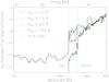 |
Fig. 1 Emergent Eddington fluxes for model S30, with |
Impact of Rmin.
The sensitivity of the X-ray fluxes on Rmin is shown in Fig. 1, where the other parameters were fixed at their center values within our small X-ray grid (i.e., fX = 0.03 and  K). In particular, the shock temperature is quite high for such a stellar model, but was chosen deliberately to allow for somewhat extreme effects.
Indeed, the only visible differences are present in the range between the He ii edge and roughly 330 Å. Shortward of the He ii edge, all fluxes are identical (though only shown down to 100 Å to allow for a better resolution), since the (cool) wind already becomes optically thick far out in the wind at these wavelengths (He ii, O iv, etc. continua, and K-shell processes). For λ> 350 Å, on the other hand, the shock emissivity becomes too low to be of significant impact.
 |
Fig. 2 Ratio of shock emissivity to total emissivity for model S30 from Fig. 1 with Rmin= 1.2 R∗. Solid line: emissivity ratio at the outer boundary, r ≈ 130R∗; dash-dotted line: emissivity ratio at the lower boundary of X-ray emission, r ≈ 1.2R∗. The box located between 300 and 320 Å highlights the strong shock emissivity leading to the corresponding emission feature present in Fig. 1. |
In this context, it is interesting to note that in ϵ CMa (B2II, the only massive hot star with EUVE data) the observed EUV emission lines in the range between 228 to 350 Å each have a luminosity comparable to the total X-ray luminosity in the ROSAT bandpass (Cassinelli et al. 1995), which also stresses the importance of this wavelength region from the observational side.
In Fig. 2, we show the ratio of the shock emissivity to the total emissivity (including averaged line processes and Thomson scattering), evaluated at the outer boundary of the wind (solid) and at 1.2 R∗ (dash-dotted), corresponding to the onset of X-ray emission in this model. A number of interesting features are visible:
-
(i)
The total emissivity in the outer wind is dominated by shockemission from just shortward of theHe ii edge until2.5 keV (the highest energy we consider in ourmodels). The emissivity in the lower wind, however, is dominatedby shock emission only until 200 eV, whilst forlarger energies the (local) shock contribution decreasesdrastically because the assumed shock temperatures(∝(v(r) /v∞)2) are rather low here (≲100 kK). The question is then: which process dominates the total emissivity at high energies in the lower wind? Indeed, this process is the re-emission from electron scattering because it is proportional to the mean intensity and quite high owing to the large number of incoming photons from above, i.e., from regions where the shock temperatures are high. This effect becomes also visible in the local radiative fluxes at these frequencies, which are negative, i.e., directed inward.
-
(ii)
Both in the outer and inner wind, the shock emission is also significant longward from the He ii edge, until λ ≈ 350 Å, thus influencing the ionization balance of important ions. Whilst the fluxes of models without shock emission and those with Rmin ≳ 2R∗ display a significant absorption edge for C iii and N iii (see Fig. 1), these edges have almost vanished in the models with Rmin = 1.2 ...1.5 R∗ because of the dominant shock emissivity increasing the degree of ionization. Even more, all models display fluxes in this region that lie well above those from models without shock emission because of the higher radiation temperatures compared to the cool wind alone.
-
(iii)
Beyond 350 Å, the shock emissivity becomes almost irrelevant (below 10%), so that the corresponding fluxes are barely affected.
-
(iv)
For the two models in which Rmin = 1.2 and 1.5 R∗, a prominent emission feature between roughly 300 and 320 Å is visible in Fig. 1. A comparison with Fig. 2 (note the box) shows that this emission is due to the dominating shock emission of the lower wind, increasing the temperatures of the radiation field beyond those of the unshocked wind.
Coming back to Fig. 1, significant flux differences between the shocked and unshocked models are visible for all values of Rmin (even for Rmin = 2 or 10 R∗) below λ ≲ 350 Å, particularly below the N iii and C iii edges as a result of higher ionization.
On the other hand, the models with Rmin = 1.2 and 1.5 R∗ are almost indistinguishable, at least regarding the pseudo-continuum fluxes. This turns out to be true also for He ii 1640 and He ii 4686, although these lines become sensitive to the choice of Rmin if we change Rmin from 1.5 to 2 R∗ because of the different intensities around the He ii edge and around He ii 303 (Lyman-alpha) in the line-forming region. We come back to this point in Sect. 5.1.2.
 |
Fig. 3 Emergent Eddington fluxes for model S30, with |
Impact of fX.
In Fig. 3, we investigate the impact of fX, which has a most direct influence on the strength of the X-ray emission (cf. Eqs. (1) and (3)). Having more X-ray photons leads to higher X-ray fluxes/luminosities and to less XUV/EUV-absorption from the cool wind because of higher ionization stages. The latter effect becomes particularly visible for the model with fX = 0.1, which was used to check at which level of X-ray emission we start to change the overall ionization stratification. Most importantly, helium (with He ii as the main ion beyond 1.2 R∗ for S30 models with typical values 0.03 ≲ fX ≲ 0.05) becomes more ionized, reaching similar fractions of He ii and He iii between 2.2 R∗ (~0.5 v∞) and 8.7 R∗ (~0.8 v∞). Also, the main ionization stage of oxygen, which is O iv in S30 models with typical X-ray emission parameters, switches to O v between 1.8 R∗ (~0.4 v∞) and 4.0 R∗ (~0.7 v∞) when fX is set to 0.1. The change in the ionization of helium (and oxygen) becomes clearly visible in the much weaker He ii edge and much higher fluxes in the wavelength range below 228 Å, compared to models with lower fX.
 |
Fig. 4 Emergent Eddington fluxes for model S30, with fX = 0.03 and |
Impact of T .
.
As shown in Fig. 4 (see also Pauldrach et al. 2001), the change in the maximum shock temperature, , becomes mostly visible for the fluxes shortward of ≈60 Å (of course, the hard X-ray band is even more affected, but not considered in our models). While for the highest maximum shock temperature considered here, = 5 × 10⁶ K (corresponding to u∞ ≈ 590km s-1), we significantly increase the population of the higher ionized atomic species, this temperature is still not sufficient to change the main ionization stages present in the wind.
4.2. Scaling relations for Lx
From an analytical point of view, Owocki & Cohen (1999) showed that for a constant volume filling factor and, neglecting the effects of radiative cooling (see below), the optically thin (with respect to the cool wind absorption) wind X-ray luminosity depends on the square of the mass-loss rate, Lx∝ (Ṁ/v∞)2, whilst the X-ray luminosity of optically thick winds scales linearly with the mass-loss rate, Lx∝Ṁ/v∞. This is the case provided that one compares models with the same shock temperatures and assumes a spatially constant X-ray filling factor. These relations become somewhat modified if there is a dependence of Ts on the wind terminal velocity, as adopted in our standard X-ray description (see also KK09).
 |
Fig. 5 Emergent X-ray luminosities (in erg s-1) as a function of Ṁ/v∞. Supergiant models S30 (asterisks), S40 (triangles) and S50 (squares) with Teff = 30, 40 and 50 kK, respectively, and mass-loss rates between 10-9 and 2 × 10⁻⁵M⊙/ yr. All models have the same X-ray properties, fx = 0.025, γx = 0.5, mx = 20, and a maximum jump-velocity, u∞ = 400km s-1, corresponding to maximum shock temperatures of 2.3 × 10⁶ K. We calculated the X-ray luminosities in the range 0.1−2.5 keV (black, green, and turquoise) and in the range 0.35 to 2.5 keV (blue, red, and magenta). The dashed lines (no fits) serve as guidelines to check the predicted behavior for optically thin (red and green) and optically thick (black) conditions. (See text.) |
However, in a more recent study Owocki et al. (2013) derived, again from an analytic perspective, scaling relations for Lx for radiative and adiabatic shocks embedded in a cool wind. At first glance, their assumptions seem quite similar to those adopted by Feldmeier et al. (1997a), which is the basis of our treatment, but in the end Owocki et al. predict different scaling relations for radiative shocks than those resulting from our modeling. This discrepancy might lead to somewhat different scaling relations for Lx, and needs to be investigated in forthcoming work; for now, we simply compare our models to the earlier results by Owocki & Cohen (1999). A similar test was carried out by KK09.
To this end, we calculated S30, S40, and S50 wind models with a fixed X-ray description: fX = 0.025, mx = 20, and γx = 0.5. For our tests, we used a constant maximum jump velocity, u∞ = 400km s-1 (corresponding to maximum shock temperatures of 2.3 × 10⁶ K) for all models to be consistent with the above assumptions.
For these models (with parameters, except for Ṁ, provided in Table 1), we varied the mass-loss rates in an interval between 10-9 and 2 × 10⁻⁵M⊙/ yr. and integrated the resulting (soft) X-ray luminosities in two different ranges: 0.1 to 2.5 keV and 0.35 to 2.5 keV.
From Ṁ≳ 10-7M⊙ yr-1 on, the wind becomes successively optically thick at higher and higher energies, although, for example, for Ṁ= 10-6M⊙ yr-1 the wind is still optically thin below ~10 Å, i.e., above 1.24 keV. Indeed, the X-ray luminosities of our corresponding models are linearly dependent on (Ṁ/v∞), as can be seen in Fig. 5 by comparing them with the black dashed line. For lower Ṁ, the wind is optically thin at most high energy frequencies and also our results closely follow the predictions (Lx ∝ (Ṁ/v∞)2), when comparing the corresponding X-ray luminosities with the red or green dashed lines.
A second finding of Fig. 5 relates to the optically thin scaling for model S50, when either starting the integration at 100 eV (turquoise squares) or at 350 eV (red squares). Whilst for S30 (asterisks) and S40 (triangles) the X-ray luminosities just increase by roughly one dex when including the range from 100 to 350 eV but still follow the predicted scaling relation, the S50 models show an increase of four orders of magnitude for the lowest Ṁ/v∞ values in this situation (and do not follow the predictions).
To clarify this effect, Fig. 6 shows the scaled (scaling proportional to  and
and  ) Eddington flux as a function of wavelength and energy for supergiant models S30 (black), S40 (green), and S50 (turquoise) with identical, low mass-loss rates, 10-8M⊙/ yr. Additionally, energies of 100, 150, and 350 eV are indicated with dotted vertical lines. Beyond 150 eV, all models, independent of their specific parameters, display the same scaled fluxes, thus verifying the optically thin scaling of X-ray luminosities (in this case, only with respect to v∞). For the S50 model, however, the energy range below 150 eV is contaminated by “normal” stellar/wind radiation, which increases as a function of Teff (see also Macfarlane et al. 1994; their Fig. 5), leading to the strong deviation from the optically thin X-ray scaling law as visible in Fig. 5. The same contamination already appears for energies higher than 150 ev for other X-ray parameter sets. Thus, the total X-ray luminosity (regarding the wind emission) of hotter objects might be overestimated when integrating until 100 eV.
 |
Fig. 6 Logarithmic, scaled Eddington flux (in units of erg cm-2 s-1 Hz-1) as a function of wavelength/energy, for the supergiant models S30 (black), S40 (green), and S50 (turquoise) with identical mass-loss rates, 10-8M⊙/ yr. All models have the same X-ray properties, as denoted in Fig. 5. The Eddington fluxes have been scaled by (R∗/R⊙)2 and (v∞/ 1000 km s-1)2 to ensure theoretically similar values of optically thin X-ray emission. The dotted lines denote energies of 350, 150, and 100 eV, corresponding to 35, 83, and 124 Å. (See text.) |
In summary, we conclude that our implementation follows the predicted scaling relations, but we also suggest choosing a lower (in energy) integration limit of 0.15 keV (or even 0.3 keV, to be on the safe side) when comparing the X-ray luminosities of different stars (both with respect to models and observations).
In this context, we note that there is a clear distinction between the observable soft X-ray and the longer-wavelength, soft X-ray, and XUV/EUV emission that is almost never directly observed, but, as already outlined, is very important for photoionizing relevant ions. Modern X-ray observatories, such as XMM-Newton/RGS and Chandra/HETG, do not have a response below 0.35 keV and 0.4 keV, respectively; even a modest ISM column makes it functionally impossible to see X-ray emission below 0.5 keV. We note, however, that ROSAT observed down to 0.1 keV, and EUVE also made a few important measurements relevant for massive stars, in particular, for ϵ CMa (B2II), e.g., Cassinelli et al. (1995).
Left side: X-ray emission parameters used to compare FASTWIND and WM-basic models (u∞/v∞ = 0.3 and γx = 1.0). Right side: Lx/Lbol (logarithmic) provided as input for WM-basic (WMB), compared with the corresponding output value from FASTWIND (FW), integrated in the frequency range between 0.1 to 2.5 keV.
4.3. Comparison with WM-basic models
Finally, we also checked the quantitative aspect of our results, by comparing with analogous WM-basic models (we note the difference in the velocity fields). As already pointed out, the X-ray description in both codes is quite similar, and there is only one major difference. In WM-basic, the user has to specify a certain value for Lx/LBol (e.g., 10-7 as a prototypical value) and the code iteratively determines the corresponding fX, which is a direct input parameter in the updated version of FASTWIND. In both cases, we used a frequency range between 0.1 to 2.5 keV.
Thus, we first calculated WM-basic models with stellar/wind parameters from Table 1 and X-ray emission parameters from Table 2. For the maximum jump velocity we assumed, as an extreme value, u∞/v∞ = 0.3, together with X-ray luminosities as shown in the sixth column of Table 2. These values then correspond to the fX values provided in the second column of the same table, which are acquired from the WM-basic output. We note here that the input values of Lx/LBol (to WM-basic) were not chosen on physical grounds, but were estimated in such a way as to result in roughly similar values for fX (in the range between 0.01 to 0.03).
To check the overall consistency, we calculated a similar set of FASTWIND models, now using the fX values from Table 2 as input. In case of consistent models, the resulting Lx values (from the output) should be the same as the corresponding input values used for WM-basic. Both these values are compared in the last two columns of Table 2. Obviously, the agreement is quite good, with differences ranging from 0.0 to 0.2 dex and an average deviation of 0.12 dex.
 |
Fig. 7 Logarithmic Eddington fluxes as a function of wavelength for supergiant models (see Tables 1 and 2). The solid lines refer to results from our updated version of FASTWIND and the dashed lines to WM-basic results (Pauldrach et al. 1994, 2001). For clarity, the S35, S40, S45, and S50 model fluxes have been shifted by −3, −6, −9, and −18 dex, respectively. |
In a second step, we compared the supergiant fluxes resulting from this procedure in Fig. 7. For clarity, the fluxes were shifted by −3, −6, −9, and −18 dex (S35, S40, S45, S50), where the solid lines correspond to the FASTWIND and the dashed lines to the WM-basic results.
The comparison shows a remarkably good agreement with no striking differences. Smaller differences in the lower wavelength range (λ< 100 Å) are related to a different frequency sampling (without an effect on the total X-ray luminosity). At longer wavelengths, these differences are related to the fact that WM-basic provides high-resolution fluxes, whilst FASTWIND calculates fluxes using averaged line opacities. For details, see Puls et al. (2005). Most important, however, is our finding that the fluxes are not only similar at high frequencies (indicating similar emissivities and cool-wind opacities), but also longward from the He ii edge, indicating a similar ionization equilibrium (modified in the same way by the emission from shocked material).
At this stage, we conclude that our implementation provides results that are in excellent agreement with the alternative code WM-basic, both with respect to integrated fluxes as well as frequency edges, which moreover follow the predicted scaling relations. Having thus verified our implementation, we now examine important effects of the X-ray radiation within the stellar wind.
 |
Fig. 8 Ionization fractions of important ions at v(r) = 0.5v∞, as a function of Teff, for models with typical X-ray emission (triangles, fX = 0.03, |
5. Results
In this section, we discuss the major results of our model calculations. In particular, we study the impact of X-ray emission on the ionization balance of important elements, both with respect to direct (i.e., affecting the valence electrons) and Auger ionization. We also discuss the impact of dielectronic recombination and investigate the radial behavior of the high-energy mass absorption coefficient, which is an essential issue with respect to the analysis of X-ray line emission.
All of the following results refer to our specific choice of the run of shock temperature (see Eqs. (6) and (7)), which, in combination with our grid-parameter γx = 1, leads to shock temperatures of  in the intermediate wind at v(r) = 0.5 v∞.
5.1. Ionization fractions
5.1.1. General effects
Even though they are only indirectly observable (particularly via UV resonance lines), ionization fractions provide useful insight into the various radiative processes in the atmosphere. In the following, we compare, for important ions (i.e., for ions with meaningful wind lines), the changes due to the combined effects of direct and Auger ionization, whilst the specific effects of Auger ionization are discussed in Sect. 5.2. We perform these comparisons for our supergiant (solid) and dwarf models (dashed) from Table 1 and for the center values of our X-ray emission parameter grid (Sect. 3), fX = 0.03, = 3 × 10⁶ K, which are prototypical in many cases. Such maximum shock temperatures might be too high for models around Teff = 30 kK, and certain effects (as discussed in the following) might thus be overestimated in this temperature range. We discuss the reaction from different parameters in the next section. We evaluated all of the ionization fractions at a representative velocity, v(r) = 0.5v∞, and these are shown in Fig. 8. To check the influence of X-ray emission, one simply needs to compare the triangles (with) and asterisks (without X-ray emission).
Carbon. Our model atom for carbon will be improved soon, but the present one (from the WM-basic data base) is already sufficient to study the impact of shock radiation. The upper panels of Fig. 8 show the results, which indicate an effect only for cooler supergiant models with Teff< 40 kK. For these objects, C iii and C iv become somewhat depleted (less than a factor of ten), whilst C v (which is, without X-ray emission, a trace ion at 30 kK) becomes significantly enhanced. For dwarfs in this temperature range, only C v is increased, since the emission (scaling with ρ2) is still too weak to affect the major ions. However, the actual filling factor in dwarfs might be much larger than 0.03; see, for example, Cassinelli et al. (1994), Cohen et al. (1997, 2008) and Huenemoerder et al. (2012). For models with Teff > 40 kK, on the other hand, the temperature is already hot enough that the ionization balance is dominated by the normal stellar radiation field and no effect from the X-ray emission is visible.
Nitrogen (2nd row) and oxygen (third row of Fig. 8) suffer most from the inclusion of shock radiation. In the following, we concentrate on the differences produced by X-ray ionization in general, whilst in subsequent sections we consider specific effects.
Nitrogen. In the cool range, the behavior of N iii, N iv and N v is very similar to the corresponding carbon ions (i.e., a moderate depletion of N iii and N iv, and a significant increase of N v, particularly at Teff between 30 and 35 K), whereas in the hot range it is different. Here, N iii and N iv continue to become depleted, but N v increases only as long as Teff< 45 kK and decreases again at 45 and 50 kK. In other words, when N v is already the main ion for non-X-ray models, it becomes (slightly) depleted when the X-rays are switched on, in contrast to C v which remains unmodified beyond 40 kK. This difference, of course, relates to the fact that C v has a stable noble-gas (He-) configuration with a high-lying ionization edge (31.6 Å) compared to the N v edge at roughly 126 Å, which allows for a more efficient, direct ionization by emission from the shock-heated plasma.
Oxygen. For almost every temperature considered in our grid, the inclusion of X-rays has a dramatic effect on the ionization of oxygen. At 30 kK, O iv becomes the dominant ion13, when for non-X-ray models the main ionization stage is still O iii, whereas at the hot end O iv becomes somewhat depleted. The behavior of O v is similar to N v (although the final depletion is marginal), and O vi displays the largest effect at all temperatures. At cool temperatures, the ionization fraction changes by 15 orders of magnitude, but there is still an increase by three to four dex even at the hottest Teff. As is well known, this has a dramatic impact on the corresponding resonance doublet.
Silicon. In almost all hot stars, the dominant ion of silicon is Si v (again a noble-gas configuration), and Si iv forms by recombination, giving rise to the well-known Si iv luminosity/mass-loss effect (Walborn & Panek 1984; Pauldrach et al. 1990). The bottom left panel of Fig. 8 shows an analogous dependence. Whilst for dwarfs (low ρ2) no X-ray effects are visible for Si iv, this ion becomes depleted for cool supergiants (Teff≲ 35 kK) at most by a factor of ten.
Phosphorus. In recent years, the observed P v doublet at λ 1118,1128 has been important14 for deriving mass-loss rates from hot star winds in parallel with constraining their inhomogeneous structure (Fullerton et al. 2006; Oskinova et al. 2007; Sundqvist et al. 2011, 2014; Šurlan et al. 2013). Thus, it is of prime importance to investigate the dependence of phosphorus on X-rays, since a strong dependence would contaminate any quantitative result by an additional ambiguity.
As already found in previous studies (e.g., KK09; Bouret et al. 2012), our results also indicate that P v is not strongly modified by X-ray emission (middle and right lower panels of Fig. 8). However, more extreme X-ray emission parameters, for example, fX = 0.05 and/or = 5 × 10⁶ K, can change the situation (see section 5.1.3). Furthermore, the apparently small change in the ionization fraction of P v at typical X-ray emission parameters (decrease by a factor of two to three) can still be of significance, given the present discussion on the precision of derived mass-loss rates (with similar uncertainties).
Regarding the ionization of P vi, cold models (30 and 35 kK) change drastically when X-ray emission is included, both for supergiants and dwarfs. Since we find less P vi in hot models with shocks (compared to models without), this indicates that the ionization balance is shifted toward even higher stages (P vii).
In this context, we note that Krtička & Kubát (2012) investigated the reaction of P v when incorporating additional, strong XUV emissivity (between 100 and 228 Å) and microclumping into their models. The former test was driven by a previous study by Waldron & Cassinelli (2010) who argued that specific, strong emission lines in this wavelength range could have a significant impact. Indeed, Krtička & Kubát (2012) were able to confirm that under such conditions15 P v becomes strongly depleted in parallel with changes in the ionization fractions of, for example, C iv, N iv, and O iv (see also Sect. 5.1.3). Further work is certainly required to identify the source of such additional emissivity, and, if necessary, to incorporate this mechanism into our FASTWIND models.
 |
Fig. 9 Helium ionization fractions as a function of local velocity, for an S30 model with (fX = 0.03 and |
5.1.2. Impact on helium
During our analysis, we noted that helium can also be affected by shock emission (see also Sect. 4.1), a finding that has been rarely discussed in related literature. In particular, He ii (and He i) can become depleted in the intermediate wind; however, this is only the case for our cooler supergiant models with 30 kK ≲Teff≲ 40 kK. The effect is strongest for S30 models, but it is barely noticeable even at S40, independent of the specific X-ray emission parameters. For all our dwarf models, no changes are visible at all.
Figure 9 shows the helium ionization fractions for an S30 model with typical X-ray emission parameters as a function of local velocity. The depletion of He ii (and, in parallel, of He i that is not displayed) is significant in the region between 0.2v∞≲ v(r) ≲ 0.8v∞, and results from the increased ionization due to the increased radiation field (in the He ii Lyman continuum) in models with shocks (note also the corresponding increase of He iii).
In Fig. 10, we compare the helium ionization fractions from our solution and a corresponding WM-basic S30 model, but now with X-ray emission parameters as tabulated in Table 2 (the major difference is a filling factor of 0.02 instead of 0.03). Here, we show the fractions as a function of τRoss to enable a comparison of the photospheric regions as well. Again, the depletion of He ii (now located between τRoss≈ 0.1...0.01) is visible, and our results coincide perfectly with those predicted by WM-basic.
Since the ionization balance already changes at very low velocities, this might affect at least two important strategic lines: He ii 1640 and He ii 4686. Most other He ii and He i lines are formed in the photosphere and remain undisturbed. From Fig. 11, we see that He ii 4686 shows stronger emission, whilst He ii 1640 shows a stronger emission in parallel with absorption at higher velocities compared to the non-X-ray model (dotted). This is readily understood since He ii 4686 is predominantly a recombination line, such that the increase in He iii leads to more emission; this is also true for He ii 1640 to a lesser extent. The lower level of this line, n = 2 (responsible for the absorption), is primarily fed by pumping from the ground-state via He ii 303. We convinced ourselves that the increased pumping because of the strong EUV radiation field leads to a stronger population of the n = 2 state (even if He ii itself is depleted), so that also the increased absorption is explained.
 |
Fig. 10 Helium ionization fractions as a function of τRoss, for S30 models calculated by FASTWIND and WM-basic, both with X-ray emission parameters from Table 2. The agreement is excellent. |
As already pointed out in Sect. 4.1, changing Rmin from 1.5 to 1.2 R∗ does not make a big difference. Increasing Rmin to 2 R∗, however, changes a lot, as visible from the dash-dotted profiles in Fig. 11. Except for slightly more emission (again because of increased He iii in regions with r> 2R∗), the difference to profiles from models without shock emission becomes insignificant, simply because both lines predominantly form below the onset radius.
5.1.3. Dependence on filling factor and shock temperature
As we have already seen above, each ion reacts somewhat differently to the imposed shock radiation. In this section we describe how a change of important X-ray characteristics affects important ions. The figures related to this section are enclosed in Appendix A. The top figure on each page shows specific ionization fractions with and without X-rays, as a function of Teff, for our supergiant and dwarf models (S30 to S50 and D30 to D50, respectively). We evaluated the ionization fractions at the location where the impact of shock radiation is most evident for the considered ion. Each of these figures contains nine panels, in which both the filling factor and maximum shock temperature are varied according to our grid, i.e., fX = 0.1, 0.3, 0.5 and = 1, 3, 5 × 10⁶ K. The onset radius, Rmin, was set to its default value for all models. The lower two figures on each page display the ionization fractions for our dwarf (left) and supergiant models (right), evaluated at the same location as above, but now overplotted for all values of fX (different colors) and (different symbols), and without a comparison to the non-X-ray case. Thus, the top figure allows us to evaluate the X-ray effects in comparison to models without shock emission, whilst the bottom two figures provide an impression on the differential effect, i.e., the range of variation.
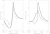 |
Fig. 11 Synthetic He ii 1640 and He ii 4686 profiles for our S30 model. Each profile corresponds to a different X-ray description. Solid: fX = 0.03, |
Carbon. C iii and C iv are significantly affected in supergiant models with 30 kK ≲Teff≲ 40 kK for intermediate to large values of fX and . The depletion of C iii and C iv reaches a factor of 10 (or even more) in cooler supergiant models when the highest values of X-ray emission parameters are adopted, which is reflected in a corresponding increase of C v. On the other hand, C iii and C iv are barely modified in supergiant models with the lowest values of fX or , which is also true for dwarf models with any value of our parameter grid (see Figs. A.1, A.2). The ionization fraction of C v also increases for the lowest values of X-ray emission parameters, again for cooler supergiant (and dwarf) models. C v remains unmodified beyond 40 kK due to its stable noble-gas configuration, as previously noted.
Nitrogen. The behavior of N iii, N iv, and N v in the colder models is similar to the corresponding carbon ions for all different X-ray descriptions. For higher Teff, increasing fX enhances the depletion of N iii and N iv in both supergiants and dwarfs, whilst the impact of is rather weak. At the largest values of X-ray emission parameters, both stages become highly depleted (one to two orders of magnitude) for all models but D30 and D35.
Shock radiation is essential for the description of N v at almost any temperature, particularly for models with Teff< 45 kK (Figs. A.3, A.4). Here, the increase of N v (compared to non-X-ray models) can reach 4 to 5 dex at the lowest temperatures. At 45 kK, only a weak impact of shock radiation can be noted, whilst for 50 kK a high depletion of N v for extreme parameters values becomes obvious. Once more, the impact of fX is more prominent than of , mainly for the coldest models where N v becomes enhanced by one order of magnitude when increasing fX from 0.01 to 0.05 and keeping constant. The hottest models with moderate to high parameters (fX≳ 0.02 and  K) indicate that N vi also becomes strongly affected by changes in the X-ray ionization.
Oxygen. Independent of the X-rays description, the depletion of O iv for hot models happens only in a specific range of the wind, between 0.4 to 0.8 v∞ (similar to the case of He ii discussed in the previous section). Also for X-ray emission parameters different from the central value of the grid, the behavior of O v is still very similar to N v, where mainly the cold models are quite sensitive to variations of fX (Figs. A.5, A.6). The shock radiation increases the ionization fraction of O v by 5 to 6 dex (when fX varies between 0.01 and 0.05, independent of ) for the coolest models, whilst these factors decrease as Teff approaches 40 to 45 kK. Models with Teff = 45 kK are barely affected, independent of the specific X-ray emission parameters. Similar to the case for N v at highest values of fX, , and Teff, the corresponding depletion of O v points to the presence of a significant fraction of higher ionization stages.
As already pointed out in Sect. 5.1.1 (see also Sect. 5.2), the X-ray radiation is essential for the description of O vi, which shows, particularly in the cold models, a high sensitivity to both fX and (Figs. A.7, A.8).
Silicon. Also when varying the X-rays description, Si iv still remains unaffected from shock emission in dwarf models. On the other hand, for cool supergiants (Teff≲ 35 kK), Si iv becomes even more depleted when fX increases (though has a negligible influence). No variation is seen in Si v, as expected because of its noble-gas configuration.
Phosphorus. P v shows a sensitivity to both fX and , but in this case is more relevant. Although no difference between models with and without shocks is seen for the lowest values of , particularly the supergiant models develop a depletion with increasing shock temperature, even at lowest fX. As noted already in Sect. 5.1.1, for extreme X-ray emission parameters the depletion of P v is significant for all models (both supergiants and dwarfs), except for D30 (Figs. A.9, A.10). Finally, even P vi becomes highly depleted for hot models (Teff≳ 40 kK) at intermediate and high values of , which indicates the presence of even higher ionization stages.
To summarize our findings: When increasing the values for fX and , the effects already seen in Fig. 8 become even more pronounced, as to be expected. For most ions, the impact of fX appears to be stronger than the choice of a specific provided the latter is still in the range considered here. However, P v and O vi (for the cooler models) show a strong reaction to variations of . Overall, the maximum variation of the ionization fractions within our grid reaches a factor of 10 to 100 (dependent on the specific ion), where lower stages (e.g., C iv, N iv, O iv, and P v) become decreased when fX and are increased, whilst the higher stages (e.g., N v, O v, O vi) increase in parallel with the X-ray emission parameters. For Si iv alone, the impact of X-rays remains negligible in all models except for S30 and S35.
 |
Fig. 12 Ionization fractions of selected ions as a function of Teff, for 14 O-star models, as detailed in Krtička & Kubát (2009, KK09); we recalculated these models here using FASTWIND. If not indicated otherwise, fractions are shown at v(r) = 0.5v∞. As in previous figures, triangles represent models with shocks and crosses indicate those without shocks. This figure largely reproduces the layout of Fig. 8 from KK09, such that differences and similarities between our and their results can be easily recognized. For details, see text. |
5.1.4. Comparison with other studies
Since the most important indirect effect of shock emission is the change in the occupation numbers of the cool wind, it is worthwhile and necessary to compare the ionization fractions resulting from our implementation with those presented in similar studies.
To this end, (i) we recalculated the models described in KK09 (ii) compared with two models (for HD 16691 and HD 163758) presented in Bouret et al. (2012), who used CMFGEN and SEI (Sobolev with exact integration, Lamers et al. 1987) fitting to calculate and derive the ionization fractions of phosphorus, and (iii) compared our results with the ionization fractions predicted by WM-basic.
Regarding the first point, we recalculated the 14 O-star models (in the temperature range between 30 and 40 kK) presented by KK09, using parameters from their Tables 2 and 3, both without and with shock emission (fX = 0.02 and u∞/v∞ = 0.3), by means of FASTWIND using H, He, C, N, O, Si, and P as explicit ions. Figure 12 shows our results for the ionization fractions of selected ions, as a function of Teff, and evaluated at v(r) = 0.5v∞. The layout of this figure is similar to Fig. 8 in KK09, and has been augmented by O vi evaluated at v(r) = 0.05v∞ and N v evaluated at v(r) = 0.8v∞, corresponding to their Figs. 9 and 10.
Indeed, there are only a few ions that display similar fractions over the complete temperature range of the O-star models considered by KK09 (which still omits the hotter O stars beyond 40 kK). For C iv, an agreement is only present for the coolest regime (Teff≤ 32 kK) where both studies predict C iv as the main ion, independent of whether X-rays are present or not. Whilst the fractions for non-X-ray models are also comparable for hotter temperatures, the X-ray models by KK09 show a much larger depletion of C iv (fractions of 10-2 to 10-3 for Teff> 34 kK) than our models reveal(still above 10-1).
For O vi, agreement between both results is present only at the hottest temperatures, whilst between 30 kK <Teff≲ 37 kK our models display a factor of ~100 lower fractions for both the non-X-ray models and the models with shock emission. The same factor is visible in the lower wind (v(r) = 0.05v∞) for the X-ray models, but the non-X-ray models are similar here.
For nitrogen (N iv and N v), on the other hand, the results are quite similar in most cases. The exception is N v for models without shocks, where our results are lower (by ~1 dex) in the intermediate and outer wind (v(r) = 0.8v∞).
For Si iv, both results fairly agree for the X-rays models, though we do not see a significant effect from including the shock emission in our calculations; in other words, X-ray and non-X-ray models yield more or less identical results. In contrast, the models by KK09 indicate a small depletion of Si iv, by a factor of roughly 2 to 3, when including the shock emission. Thus, our non-X-ray models have less Si iv than those by KK09.
Again, phosphorus (in particular, P v) has to be analyzed in more detail. Comparing the last two panels of Fig. 12 with Fig. 8 from KK09, we see that our ionization fractions for P v agree with KK09 in the coolest models and in the hottest models regarding P vi. In the other temperature ranges, however, differences by a typical factor of 2 (regarding P v) and 2 to 5 (regarding P vi) are present. In their Fig. 12, KK09 show the radial stratification of the phosphorus ionization fractions for their model of HD 203064, whilst the corresponding results from our implementation are shown in Fig. 13. Both codes yield quite similar fractions for P iv and P v (with and without X-rays) in the external wind. The same is true for P vi in the model with X-rays, but we have considerably less P vi for the non-X-ray model. Prominent differences are visible in the lower wind and close to the lower boundary. We attribute this difference to a boundary condition (in the models by KK09) at very low optical depths, where the electron temperature is still close to the effective temperature. (Indeed, we were not able to find statements or figures related to the photospheric structure of the models in papers by Krtička and coworkers, so our argument is somewhat speculative.) Thus far, it is conceivable that a low ionization stage (P iv) dominates their internal atmosphere (followed by P v and negligible P vi), whilst in our case it is the reverse, and P vi dominates owing to much higher temperatures.
To check these discrepancies further, we also compared our results with calculations performed with CMFGEN. In particular, we concentrated on two supergiant models at roughly 35 kK and 40 kK (HD 163758 and HD 16691, respectively), as described by Bouret et al. (2012). These models used an X-ray emitting plasma with constant shock temperature, Ts(r) = 3 × 10⁶ K, a filling factor corresponding to Lx/Lbol = 10-7, and an onset radius corresponding to 200 to 300 km s-1 (J.-C. Bouret, priv. comm.). In Fig. 14, we present our results for P iv and P v; these can be compared with Fig. 10 of Bouret et al., showing P v alone. Though our models S35 and S40 (here we use a clumped wind with reduced mass-loss rates to ensure comparable wind structures) do not have identical parameters, and in particular, our shock temperatures increase with velocity, the ionization fractions behave similarly. In the cooler model (solid), the ionization of P v decreases with velocity and in the hotter model (dashed), this ionization increases outward. This is because in the cooler model, P v is the dominant ion at low velocities, recombining to P iv, whilst in the hotter model P vi dominates at low velocities, recombining to P v in the run of the wind. Of course, there are some quantitative differences, particularly in the intermediate wind16, but we attribute these to a different stratification of the clumping factor, fcl, and to a different description of the X-ray emitting plasma; concerning the reaction of P v on various X-ray emission parameters, see Fig. A.10.
 |
Fig. 13 Radial stratification of phosphorus ionization fractions, as a function of τRoss, for our model of HD 203064 at Teff = 34.5 kK (see KK09 for stellar, wind, and X-ray emission parameters). In our implementation, P v is barely modified by the X-ray radiation field, whilst a considerable impact is seen for P vi. |
 |
Fig. 14 Ionization fractions of P iv (asterisks) and P v (triangles) as a function of normalized velocity for an S35 (solid) and S40 (dashed) model. Both models were calculated with a clumping factor fcl = 20, and a mass-loss rate reduced by a factor of ~4 compared to the values provided in Table 1. Compare with Fig. 10 in Bouret et al. (2012). |
As a final test, we compared our solutions to the predictions by WM-basic, using our dwarf and supergiant models (Table 1 and X-ray emission parameters from Table 2). The results are shown in Figs. B.1 and B.2 (Appendix B). The range of comparison extends from 30 to 50 kK, i.e., to much hotter temperatures than in the comparison with KK09.
Overall, the agreement between FASTWIND and WM-basic is satisfactory and all trends are reproduced. However, we also find discrepancies amounting to a factor of 10 in specific cases, particularly for Si iv. Typical differences, however, are on the order of a factor of two or less. We attribute these discrepancies to differences in the atomic models, radiative transfer, and the hydrodynamical structure, but conclude that both codes yield rather similar results with the possible exception of Si iv, which needs to be reinvestigated in future studies.
In Fig. B.3 we see how some of the encountered differences (compared at only one depth point, v(r) = 0.5v∞, except for N v) translate to differences in the emergent profiles. As prototypical and important examples, we calculated line profiles for N iv 1720, N v 1238,1242, O v 1371, O vi 1031,1037, and P v 1117,1128 and compare them with corresponding WM-basic solutions for models S30, D40, S40, D50, and S50 (for model D30, all these lines are purely photospheric and thus were not part of this comparison). Both the WM-basic and FASTWIND profiles were calculated with a radially increasing microturbulence with maximum value vturb(max) = 0.1v∞, which allows for reproducing the blue absorption edge and black trough (see Sect. 2.1) in the case of saturated P Cygni profiles.
This comparison clearly shows that in almost all considered cases the agreement is satisfactory; WM-basic includes the photospheric background, whilst FASTWIND only accounts for the considered line(s). Larger differences are present only (i) for N iv and O v in the outer wind, where FASTWIND produces more (N iv) and less (O v) absorption, respectively; and (ii) for strong P v lines, where FASTWIND predicts higher emission.
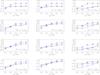 |
Fig. 15 Ionization fractions of ions most affected by Auger ionization, at different depth points. All models have typical X-ray emission parameters (fX = 0.03 and |
5.2. Impact of Auger ionization
All X-ray models discussed so far include the effects from direct and Auger ionization, which was shown to play an important role for the ionization balance in stellar winds (e.g., Cassinelli & Olson 1979; Olson & Castor 1981; Macfarlane et al. 1994; Pauldrach et al. 1994). In the following, we investigate the contribution of Auger ionization to the total ionization in more detail, particularly since this question is still under debate.
Figure 15 shows how specific ions are affected throughout the wind for dwarf and supergiant models with different Teff and typical X-ray emission parameters (fX = 0.03 and = 3 × 10⁶ K). Each ion is shown at three different locations: v(r) = 0.3v∞ (close to the onset of the shock emission), v(r) = 0.6v∞ (intermediate wind), and v(r) = 0.9v∞ (outer wind).
Two general comments: (i) significant effects are to be expected only for very high ionization stages, since in the majority of cases Auger ionization couples ions with a charge difference of two (but see Sect. 2.2). For example, C iv should remain (almost) unmodified, since C ii is absent in O and, at least, early B stars. In addition, the K-shell absorption of C iv (with a threshold at 35.7 Å), resulting in the formation of C v (with a charge difference of one), is in most cases (but see below) negligible compared to the direct ionization of C iv (with a threshold of ~192 Å for the ground-state ionization). Given the radiation field is stronger at longer wavelengths, this favors direct versus Auger ionization. In contrast, O vi should become significantly affected, since O iv is strongly populated in O stars, and the transition threshold for the direct ionization from O v (at ~109 Å) is now closer to the K-shell edge. Consequently, the transition rates (depending on the corresponding radiation field) are more similar than in the case of C iv.
(ii) In the same spirit, Auger ionization should become negligible, at least in most cases, for the hotter O stars (see also Sect. 4). Once Teff is high, more direct ionization is present because of the stronger radiation field at the corresponding, lower frequency edges, and consequently the impact of Auger ionization should decrease. This argumentation is basically correct, but the actual results also depend on the wind-strength, since higher densities lead to more X-ray emission (for identical fX), which increases the impact of Auger ionization. For example, if we check for the behavior of N vi at 0.9 v∞ in Fig. 15, we see that for D40, D45, and D50 there is indeed no effect, whilst for S40 and S45 Auger ionization still has a certain influence.
We now examine Auger ionization in greater detail. First, we note that all ions from C, N, O, Si, and P that are not shown in Fig. 15 are barely changed by Auger ionization with a maximum difference of ± 0.08 dex (corresponding to factors of 0.8 to 1.2) in the fractions calculated with and without Auger.
For carbon, C v is the only ion that under specific conditions becomes affected by Auger ionization. As visible in the first line of Fig. 15, cold supergiant models show an increase of C v in the outer wind when Auger is included, since in this case the radiation field at the corresponding K-shell edge becomes very strong, compared to the radiation field around 192 Å (see Fig. 7). This increase is compensated by a similar decrease of C iv, which, in absolute numbers, is quite small.
N vi (second line in Fig. 15) is the only nitrogen ion where larger changes are noted. In cool dwarfs, it already becomes influenced at 0.3 v∞, and also in the intermediate wind, which is also true for model S30. In the outer wind, differences appear clearly for all models, except for dwarfs with Teff≳ 40 kK. The corresponding change in N iv, on the other hand, is marginal, again because N vi itself has a low population, even when Auger is included.
O v behaves similar to N v (mostly no changes), but now a weak effect appears in the outer wind of cool supergiants (third line of Fig. 15), and even for O vi (compare to the reasoning above), changes in the lower and intermediate wind are barely visible (if at all, then only for the S30 model; see last line of Fig. 15). In the outer wind, however, considerable differences in O vi (up to three orders of magnitude) can be clearly spotted for all supergiants and cooler dwarf models, similar to the case of N vi. The effect only becomes weak for the hottest models. Figure 16 shows an example for an S40 model where the second-most populated oxygen ion (O v) changes to O vi after the inclusion of Auger ionization.
 |
Fig. 16 Radial stratification of oxygen ionization fractions, as a function of τRoss, for an S40 model with fX = 0.03 and |


Finally, the K-shell edges for phosphorus (not implemented so far) and silicon (with quite low cross sections) are located at such high energies (>2 keV or >6 Å) that the corresponding Auger rates become too low to be of importance, at least for the considered parameter range.
To conclude, in most cases the effects of Auger ionization are only significant in the outer wind (for a different run of shock temperatures, they might become decisive already in the lower or intermediate wind), and for highly ionized species. The effect is essential for the description of N vi and O vi, particularly in the outer wind. Thus, and with respect to strategic UV resonance lines, it plays a decisive role only in the formation of O vi 1031,1037 (but see also Zsargó et al. 2008).
 |
Fig. 17 Ionization fractions of oxygen, as a function of τRoss, for a D45 model with fX = 0.03 and |

5.3. Dielectronic recombination of O V
After comparing the results from our first models accounting for shock emission with corresponding WM-basic results, we found that in a specific parameter range (for dwarfs around 45 kK) both codes delivered largely different fluxes around the O iv edge at ~160 Å; these different fluxes could be tracked down to completely different ionization fractions of oxygen. In particular, our models displayed more O v and less O iv than calculated by WM-basic.
After investigating the origin of this discrepancy, we found that we had inadvertently not included the data for dielectronic recombination17 (hereafter DR) in our oxygen atomic model. Thus, DR processes had not been considered for oxygen. (For Si, P, and C v, corresponding data are still missing in our database.)
A series of studies had recently reconsidered the effects of DR with respect to nitrogen (Rivero González et al. 2011, 2012a,b), however no significant effects were found, particularly concerning the formation of the prominent N iiiλλ4634-4640-4642 emission lines that were previously attributed to DR processes (Bruccato & Mihalas 1971; Mihalas & Hummer 1973).
Nevertheless, we subsequently included DR in our oxygen atomic model and were surprised by the consequences. In a large region of our model grid, we found the changes to be negligible for the fluxes. However, in all of the supergiant models and in the dwarf models around 45 kK, the ionization fractions were strongly affected, which led to a decrease of O v, typically by a factor of 10 to 50.
For our most problematic D45 model, DR proved to be essential even to predict the correct main ion throughout the wind and to produce a reliable SED around the O iv edge. Figure 17 shows the impact of DR for this model. Indeed, the population of every ionization stage becomes modified in the wind, but for O iv this difference is large enough to change it to the main stage of the model. The reason for such drastic impact in the region around D45 is based on the fact that only here the X-ray ionization is potentially able to allow for the dominance of O v (see Fig. 8), which then can be compensated by quite strong dielectronic recombination rates18.
Nevertheless, since in the majority of models O v becomes severely depleted (see above), independent of whether it is a main ion or not, and because also O vi is affected, this leads to considerable changes in the corresponding UV lines. Thus, we conclude that DR is inevitable for a correct treatment of oxygen. Moreover, because of this strong impact, the precision of corresponding data needs to be rechecked. As a final remark, we note that the inclusion of DR also has an impact on non-X-ray models, but to a much lower extent.
5.4. Mass absorption coefficient
As already mentioned in Sect. 1, in recent years the X-ray line emission (observed by means of Chandra and XMM-Newton) has also been modeled and analyzed by various groups. Such analysis particularly allows us to obtain constraints on the presence, structure, and degree of wind inhomogeneities at X-ray wavelengths (e.g., Oskinova et al. 2006; Sundqvist et al. 2012a; Leutenegger et al. 2013b). These models also allow us to independently “measure” the mass-loss rates of O-star winds (e.g., Hervé et al. 2013; Cohen et al. 2014b; Rauw et al. 2015) and even to derive nitrogen and oxygen abundances (Oskinova et al. 2006; Zhekov & Palla 2007; Nazé et al. 2012; Leutenegger et al. 2013a; primarily, these abundance determinations involve measuring the strengths of corresponding emission lines in the soft X-ray regime, and possibly correcting them for absorption. However, these diagnostics are not wind absorption diagnostics, but absorption is only a correction needed to derive line luminosities).
One of the assumptions made by various authors is to consider the mass absorption coefficient of the cool wind material, κν(r), as spatially constant, which simplifies the analysis (Owocki & Cohen 2006; Leutenegger et al. 2013b; Cohen et al. 2014b). Other groups include detailed predictions for the spatial and frequency dependence of κν(r), calculated by means of POWR (e.g., Oskinova et al. 2006) or CMFGEN (e.g., Hervé et al. 2013; Rauw et al. 2015), and there is an ongoing discussion about whether the assumption of a spatially constant κν is justified and how far it affects the precision of the deduced mass-loss rates. Though Cohen et al. (2010, 2014b) investigated the variation of κν(r) and its influence on the derived parameters based on selected CMFGEN models (also accounting for variations in the CNO-abundances), a systematic study has not been performed so far; in this section we carry out this study.
At first, we consider why and under which conditions κν should become more or less spatially constant. The prime reason for this expectation is the fact that the K-shell cross sections (at threshold and with respect to wavelength dependence) of the various ions of a specific atom are quite similar, and that the corresponding edges (for these ions) lie close together. Provided now that (i) all ions that are present in the wind are actually able to absorb via K-shell processes; and (ii) that there are no background opacities from other elements, κν(r) indeed becomes (almost) spatially constant, since the total opacity is then the simple sum over the K-shell opacities from all contributing atoms,  (9)where αk is the elemental abundance, YHe the helium abundance (both quantities normalized to hydrogen), and mH the hydrogen mass. The parameter k denotes the atomic species, j is the ion, nk,j is the occupation number of ion (k,j), and σk,j ≈ σk is the K-shell cross section because it is almost independent of j. In the last step of the above derivation, we assumed that the atmosphere consists mostly of hydrogen and helium.
Thus, we have to check under which conditions restrictions (i) and (ii) might no longer be valid. For the light and abundant elements CNO, K-shell absorption is no longer possible for C v, N vi, and O vii. For these ions, only ordinary, outer-shell ionization is present, but also here the cross sections are not too different from the K-shell processes (both with respect to strength and location of edge). Thus, even for highly ionized winds (hot or with strong X-ray emission), where C v, N vi, and O vii are actually present somewhere, the above approximation is still justified. In so far, restriction (i) should play no role, since even higher ionization stages are not too be expected to be significantly populated.
 |
Fig. 18 Contour plots illustrating the radial dependence of the mass absorption coefficient, κν(r), as a function of wavelength. The top panel refers to model D30, and the bottom panel indicates model S40, which both have typical X-ray emission parameters ( |
Regarding restriction (ii), the situation is different. The prime background is given by the He ii bound-free opacity, which becomes strong in cool and/or helium-recombined winds19, where in the following we always refer to the recombination of He iii to He ii. Hillier et al. (1993) already showed the importance of outer-wind helium recombination on wind opacity and emergent soft X-ray emission.
We now check the maximum influence of the He ii bound-free opacity at important K-shell edges. For a crude estimate, we approximate its frequency dependence by (ν0/ν)3 = (λ/λ0)3, and assume the worst case that He ii is the only He ion present in the wind. Then, a lower limit for the opacity ratio at specific K-shell edges can be approximated by 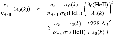 (10)where σ0 is the cross section at the corresponding edge. Using solar abundances from Asplund et al. (2009), λ0(C) ≈ 35 Å and λ0(O) ≈ 20 Å, σ0 ≈ 1.6, 0.9, and 0.5 × 10⁻¹⁸ cm2 for the threshold cross sections of He ii, carbon (K-shell), and oxygen (K-shell), respectively, we find κC/κHeII(35 Å) ≳ 0.42 and κO/κHeII(20 Å) ≳ 2.3. Thus, for cool and/or He-recombined winds, the He ii opacity dominates at the carbon K-shell edge, whilst at the oxygen edge the K-shell opacities are substantially larger than the background. Thus, we would predict that somewhat below ≈20 Å (beyond 620 eV) restriction (ii) becomes valid, and that κν should become depth independent. Vice versa, the mass absorption coefficient should vary with radius longward from the oxygen or carbon K-shell edge whenever the background mass absorption coefficient varies, which is is mostly due to changes in the He ii ionization throughout the wind.
In the following, we discuss these issues by means of our grid models; all of these models have shock emission described by our typical parameters ( = 3 × 10⁶ K and fX = 0.03). In particular, we provide estimates for suitable means of κν, as a function of Teff.
Figure 18 shows contour plots of the radial dependence of the mass absorption coefficient in the D30 model (upper panel) and in the S40 model (lower panel) as a function of wavelength. In accordance with our expectation from above, in both panels we note that κν becomes constant when r ≳ 1.2 R∗ and the wavelength is lower than 20 Å (log λ ≲ 1.3), to be on the safe side. In most cases, the radial limit, arising from fluctuations in the opacity background, is even lower.
Longward of the O iv K-shell edge (λ> 21 Å), the radial variation of κν depends on effective temperature and wind density. For the D30 model, κν increases significantly with wavelength, but nevertheless does not vary with radius because in this case the dominating ionization fraction of He ii remains constant throughout the wind. In contrast, somewhat hotter models (e.g., D35), but particularly models with denser winds such as S40 display a different behavior. Here, the lower wind is dominated by He iii, so that the background is weak, and one can already discriminate the C iv and C v edges around 10 R∗ (indicated as dashed lines). Compared to the dwarf models, the total κν in the inner wind is much lower, shows much more structure, and is influenced by the carbon and nitrogen opacities. Once helium begins to recombine in the outer wind, the background begins to dominate again and the K-shell features vanish.
 |
Fig. 19 Upper four panels: radial variation of the mass absorption coefficient in dwarf models for specific values of wavelength. Black: Teff = 30 kK; green: 35 kK; blue: 40 kK; magenta: 45 kK; and red: 50 kK. All models have been calculated with |
Figure 19 (upper part) illustrates the radial variation of the mass absorption coefficient for different wavelengths, and for our dwarf models with Teff from 30 to 50 kK. Independent of Teff, the radial variation of κν is marginal at (and below) 10 Å. Around 20 Å, the variations in the inner/intermediate wind (until 10 R∗) are somewhat larger, due to changes in the oxygen ionization, where the specific positions of the corresponding edges play a role (see also Fig. 20, upper panel). At 30 Å, we see a separation between D30 (black) with high values of κν (He ii dominating), hot models with low values of κν (C v + low background, since helium completely ionized), and D35 (green) with a significantly varying κν, due to the recombination of He iii in the external wind. At 40 Å, finally, the behavior is similar, and only the κν values for the cooler models are larger, because of the increasing He ii background.
 |
Fig. 20 Upper panel, top: density-weighted mean (Eq. (11)) of the mass absorption coefficient, |
The analogous situation for supergiants is shown in Fig. 19, lower part. Whilst for dwarfs the variation of κν (when present) vanishes at around 10 R∗, here it is visible throughout the wind up to large radii for all but the coolest (black) and hottest (red) models. The limiting values (at the outermost radius) are similar to those of the corresponding dwarf models at Teff = 30 and 35 kK (recombined) and at Teff = 50 kK (He iii). In contrast, for models with Teff = 40 and 45 kK the opacity continues to increase outward, since the recombination is still incomplete.
Hervé et al. (2013) provided a similar figure to investigate the radial variation of κν, in this case for a model of ζ Pup calculated by CMFGEN. While the stellar parameters roughly agree with our S40 model, these authors considered a clumpy wind (with volume filling factor fV = 0.05), and nuclear processed CNO abundances. Because this model shows an earlier recombination of helium with a larger nitrogen and weaker oxygen K-shell edge, the actual values of κν are somewhat different from our results (except at shortest wavelengths), but the basic trends are quite similar. In particular, our results support the idea of Hervé et al. (2013) of parameterizing the run of κν: In any of the κν(r)-curves shown in Fig. 19, these curves either increase or slightly decrease, but eventually reach a plateau from a certain radius on (which differs for each model). This radius then separates two different regimes of κν that might be parameterized in an appropriate way (see Hervé et al. 2013 for details).
Instead of a parameterization, it is also possible to calculate meaningful averages of κν and the corresponding scatter. The size of this scatter then allows us to conclude when (w.r.t. wavelength and Teff) a spatially constant mass absorption coefficient might be used to analyze X-ray line profiles. Instead of a straight average, we use a density-weighted average (and a corresponding variance) to account for the fact that the optical depth, τν, is the quantity that needs to be calculated with high precision ![Mathematical equation: \begin{eqnarray} \tau_\nu = \int^{R_{\rm max}}_{R_{\rm min}} \kappa_\nu(r) \rho(r) \dd r &=:& \bar \kappa_\nu \int^{R_{\rm max}}_{R_{\rm min}} \rho(r) \dd r \qquad \qquad \qquad\Rightarrow \nonumber \\ \label{meankappa} \bar \kappa_\nu &=& \int^{R_{\rm max}}_{R_{\rm min}} \kappa_\nu(r) f(r) \dd r, \\ \label{varkappa} {\rm Var}(\kappa_\nu) &=& \int^{R_{\rm max}}_{R_{\rm min}} (\kappa_\nu(r)-\bar \kappa_\nu)^2 f(r) \dd r\\ {\rm with \quad p.d.f.} \quad f(r)\dd r &=& \rho(r)\dd r/\left[\int^{R_{\rm max}}_{R_{\rm min}} \rho(r) \dd r\right]. \nonumber \end{eqnarray}](/articles/aa/full_html/2016/06/aa27718-15/aa27718-15-eq178.png) In this approach, the density weights correspond to a probability distribution function (p.d.f.). The quantity Rmin indicates the lower boundary for the averaging process and must not be confused with the onset radius of the X-ray emission.
In this approach, the density weights correspond to a probability distribution function (p.d.f.). The quantity Rmin indicates the lower boundary for the averaging process and must not be confused with the onset radius of the X-ray emission.
Figure 20 (upper panel) shows such mean mass absorption coefficients,  , as a function of wavelength, averaged over the interval between 1.2 and 110.0 R∗, for our dwarf models; the impact of this chosen interval is discussed below. The lower panel denotes the relative standard deviation,
  . Also here, cold and hot models are clearly separated with D35 in between (cf. with Fig. 19, upper part): for λ ≳ 21 Å, the cold models are affected by a strong He ii-background, whilst this background is weak for the hotter models. In this long wavelength region, the radial variation of κν is large for model D35, as a result of recombining helium. There is also a considerable scatter between 18 and 21 Å because of radial changes in the oxygen ionization. Overall, however, the assumption of a constant mass absorption coefficient (suitably averaged) is not too bad for the complete wavelength range (scatter below 20%), if we exclude model D35. Below 18 Å, the scatter becomes negligible, except at the Ne, Mg, and Si edges.
Even if κν(r) can be approximated by a single number, , the question is then about its value. For comparison, the dashed line in Fig. 20 shows the (analytic) estimate,  as provided by Eq. (9), using only solar abundances and K-shell opacities with cross sections from C iv, N iv, O iv, Ne iv, Mg iv, and Si iv. At least for hotter dwarf models, this estimate is quite appropriate when comparing to the actual case, except for a somewhat erroneous description of the carbon edge(s): since C v dominates in the hotter models and there is a ~4 Å difference between the C iv K-shell and the C v edge, this region is badly described by our approximation. For cooler dwarf models, on the other hand, the difference between the dashed and solid curves is (mostly) due to the helium background, which varies as a function of Teff, log g, and wind density, thus affecting the actual value of . Even below 18 Å, this background is still non-negligible for model D30 with a maximum deviation of roughly 30% close to the oxygen edge. Nevertheless, we conclude that for all dwarf models with Teff ≥ 35 kK, the assumption of a constant mass absorption coefficient approximated by is justified when λ ≤ 18 Å (at least within our present assumptions, i.e., solar abundances and unclumped winds with optical depths that are not too large, such that the averaging down to 1.2 R∗ is reasonable). In all other cases, results from NLTE-atmosphere modeling should be preferred.
The situation for our supergiant models is displayed in Fig. 20, lower panel. Below 20 Å, the situation is similar to the dwarf case, although here the background is lower, even for the coolest model, and the approximation of by might now be applied at all temperatures. For λ> 30 Å, however, almost all models (except for S50) can no longer be described by a radially constant κ, since all models with Teff ≤ 45 kK show recombining helium of different extent, leading to strong variations throughout the wind.
Thus far, we considered models with solar abundances and unclumped winds. To illustrate the variation of the total and K-shell opacities with abundance (already investigated for particular models by, e.g., Cohen et al. 2010, 2014b), the dotted lines in Fig. 20 denote the approximate K-shell opacities, , for the case of highly processed CNO material based on the abundances derived for ζ Pup by Bouret et al. (2012). Here, the carbon and oxygen abundances are depleted by 0.8 and 0.6 dex, respectively, whilst the nitrogen abundance is extremely enhanced (by ~1.3 dex) compared to the solar values. Such a composition leads to weak C and O K-shell edges, but to an enormous nitrogen edge (dotted vs. dashed line).
Now, if the individual abundances are known during an analysis, there is no problem, and κν might be approximated by either below 18 Å or calculated by means of NLTE-model atmospheres, simply accounting for these abundances. However, considerable uncertainties even in the low wavelength regime might result when the abundances are not known. From comparing the dashed and dotted line, we estimate this uncertainty as roughly 50% for , and thus for τν and Ṁ (when the mass-loss rate shall be derived). A similar value has already been estimated by Cohen et al. (2014b). In the range between the oxygen and carbon edge (20 to 35 Å), the situation is even worse and we conclude that the corresponding absorption coefficients are prone to extreme uncertainties when the abundances have to be adopted without further verification. In particular, getting κν right around 25 Å is important for measuring the N emission lines at and close to that wavelength (e.g., N vi 24.9, N vii 24.78), and thus measuring the N abundance directly. At longer wavelengths, however, where κν varies even more strongly with radius, and even though nitrogen emission lines are not directly affected, the (direct) ionization of elements such as CNO is affected, and so optical and UV line strengths are affected too, as discussed in the previous sections.
The impact of clumping is less severe. Comparing Fig. C.1 (Appendix) with Fig. 20, we see that models accounting for optically thin clumping (“micro-clumping”) with typical clumping factors (fcl = 20 corresponding to a volume filling factor, fV = 0.05) and adequately reduced mass-loss rates give rather similar results compared with unclumped models. Again, the scatter of κν is negligible below 18 Å. “The region longward of 20 Å is the only region that is more strongly contaminated by the He ii background, since the clumped models recombine earlier than the unclumped models. The K-shell mass absorption coefficients themselves are not affected by optically thin clumping, since the opacities scale linearly with density.
Finally, Fig. C.2 (Appendix) investigates the consequences of averaging κν in the outer wind alone (in the interval between 10 and 110 R∗), which would be adequate if the wind would become optically thick at such radii (which for short wavelengths and O-star winds is quite unlikely because of the low value of κν). Anyway, below 18 Å the differences to the original values are small. The hot dwarf models now behaves almost exactly as estimated by because He ii vanishes in the outer regions of these objects. Further conclusions on this topic are provided in the next section.
6. Summary and conclusions
In this paper, we described the implementation of X-ray emission from wind-embedded shocks into the unified, NLTE atmosphere/spectrum synthesis code FASTWIND, discussed various tests, and presented some initial results.
Our implementation follows closely corresponding work by Pauldrach et al. (2001) for WM-basic, which in turn is based on the shock cooling zone model developed by Feldmeier et al. (1997a) with the additional possibility of considering isothermal shocks. The (present) description of the shock distribution and strength is provided by four input, “X-ray emission parameters”, controlling the filling factor, the run of the shock temperature, and the radial onset of the emitting plasma. We account for K-shell absorption and Auger ionization, allowing for more than one final ionization stage due to cascade ionization processes.
Most of our test calculations are based on a grid of 11 models (supergiants and dwarfs within Teff = 30 to 55 kK), each of them with nine different X-ray emission parameter sets, but we calculated many more models for various comparisons, including models with optically thin clumping.
A first test investigated the reaction when varying important X-ray emission parameters. For radially increasing shock strengths, the emergent flux remains almost unaffected if the onset radius is lowered compared to its default value (roughly 1.5 R∗), whilst increasing the onset has a considerable effect in the range between ~350 Å and at least the He ii edge. Filling factor and maximum shock temperature affect the ionization fractions, particularly of the highly ionized species. We confirm some earlier predictions for scaling relations for X-ray luminosities (as a function of Ṁ/v∞) in the case of optically thin and thick continua, (though a discrepancy with recent work by Owocki et al. 2013 was identified, which needs to be investigated further), but we noted that for our hottest models these luminosities can become contaminated by normal stellar radiation for energies below ~150 eV. Thus, we suggested choosing a lower integration limit of 0.15 keV (or even 0.3 keV, to be on the safe side) when comparing the X-ray luminosities of different stars or theoretical models. Finally, we found an excellent agreement between FASTWIND and WM-basic fluxes, demonstrating a similar ionization balance, and a satisfactory agreement between corresponding X-ray luminosities. Overall, the impact of typical shock emission affects the radiation field in the wind for all wavelengths λ< 350 Å, thus modifying all photo rates for ions with ionization edges in this regime.
Investigating the ionization fractions within our model grid allowed us to study the impact of shock radiation for the proper description of important ions, i.e., those with meaningful wind lines (e.g., C iv, N iv, N v, O v, O vi, Si iv, and P v). If we denote models with Teff = 30 to 35 kK as “cool”, models with Teff = 35 to 45 kK as “intermediate”, and models with Teff = 45 to 55 kK as “hot” (note the overlap), we can summarize our findings as follows. Those ions not (or only marginally) affected by shock emission (with typical parameters and our parameterization of the shock strengths) are
-
in dwarfs: C iii, C iv,N iii (cool),N iv (cool),O iv (intermediate),Si iv,P v (cool+intermediate)
-
in supergiants: C iii (hot), C iv (hot), N iv (cool), O iv (intermediate), Si iv (hot).
In almost all of the other cases, the lower stages (C iii, C iv, N iii, N iv, O iv (hot), Si iv, and P v) are depleted, i.e., corresponding wind lines become weaker, and the higher stages (N v, O iv (cool), O v, O vi) become enhanced, i.e., corresponding wind lines become stronger when accounting for shock emission.
We studied in some detail how the ionization fractions change when the two most important parameters, filling factor and maximum shock temperature, are varied. For most ions, the filling factor has a larger influence than , but particularly O vi and P v (the latter only for higher filling factors and shock temperatures) show a strong reaction to both parameters.
As a result of the importance of P v with respect to mass loss and wind-structure diagnostics, we reinvestigated the behavior of P v and confirm previous results that for typical X-ray emission parameters this ion is only weakly or moderately affected (by factors of two for intermediate and hot supergiants at v(r) /v∞ = 0.5 and by factors of 10 at v(r) /v∞ = 0.8). For a strong X-ray radiation field, however, the depletion can reach much higher factors. A comparison of P v ionization fractions with results from CMFGEN (Bouret et al. 2012) provided a reasonable agreement.
Not only metals. but also He can be affected by shock emission because of the location of the He ii edge and He ii 303 in the EUV. Significant effects, however, have only been found in the winds of cool supergiants, where particularly He ii 1640 (emission and high-velocity absorption) and He ii 4686 (emission) become stronger because of increased recombination cascades and increased pumping of the n = 2 level in the case of He ii 1640.
When comparing our ionization fractions with those calculated by WM-basic, we found a good, though not perfect, agreement, which we found to be true for various UV line profiles as well. When comparing with Krtička & Kubát (2009), on the other hand, a similar agreement over the complete covered temperature range was found only for few ions; for the majority, such agreement is present only at specific temperatures.
It is well known that Auger ionization can play an important role for the ionization balance of specific ions. To further investigate this issue, we compared the ionization fractions of all ions considered in this study when including (default) or excluding this process in our NLTE treatment. Overall, we found that only N vi and O vi (as previously known) are significantly affected by Auger ionization, but, at least in our models (with radially increasing shock temperatures), these ions are only affected in the outer wind. For the inner and intermediate wind, direct EUV/XUV ionization due to shock emission dominates, which is generally true for all other considered ions. (Additionally, the presence of a low-density interclump medium is essential for the formation of O vi in clumped winds; see Zsargó et al. 2008.)
As an interesting by-product of our investigation, we found that dielectronic recombination of O v can have a considerable influence on the ionization balance of oxygen (O iv vs. O v), particularly for dwarfs around 45 kK.
In the last part of this paper, we provided an extensive discussion of the high-energy mass absorption coefficient, κν, regarding its spatial variation and dependence on Teff. This topic is particularly relevant for various approaches to analyzing X-ray emission lines. To summarize and conclude, we found that (i) the approximation of a radially constant κν can be justified for r ≳ 1.2 R∗ and λ ≲ 18 Å, and also for many models at longer wavelengths. (ii) In order to estimate the actual value of this quantity, however, the He ii background and, to a lesser extent, the bound-free background from highly abundant metals needs to be considered from detailed modeling, at least for wavelengths longer than 18 to 20 Å. Moreover, highly processed CNO material can change the actual value of κν considerably, particularly for λ ≳ 20 Å, and estimates for the optical depth, τν, become highly uncertain in this regime if the individual abundances are unknown.
In this context, it is reassuring to note that, for example, the mass-loss determinations by Cohen et al. (2014b) using X-ray line spectroscopy (via determining the optical depths of the cool wind material, under the assumption of spatially constant κν) rely on 16 lines observed by Chandra, where 14 out of these 16 lines are shortward of 19 Å. The issues summarized above will be a much bigger problem for O vii and nitrogen X-ray emission line measurements (O vii at 21.6–22.1 Å, N vii at 24.78 Å, and N vi at 24.9 Å), which are planned to independently constrain, with high precision, the nitrogen/oxygen content in (a few) massive O stars (Leutenegger et al. 2013a). To this end, a detailed modeling of κν (particularly regarding the helium ionization) will certainly be advisable for such an analysis.
Now that we have finalized and carefully tested our implementation of emission from wind-embedded shocks, we are in a position to continue our work on the quantitative spectroscopy of massive stars. As outlined in the introduction, we will concentrate on determining the carbon and oxygen abundances in O and early B stars observed during the two VLT-flames surveys conducted within our collaboration, by means of optical and, when available, UV spectroscopy. During such an analysis, the X-ray emission parameters need to be derived in parallel with the other, main diagnostics, at least in principle. We then have to check how far the derived abundances depend on corresponding uncertainties.
We further note that any such UV analysis also needs to consider the effects of optically thick clumping (e.g., Oskinova et al. 2007; Sundqvist et al. 2011, 2014; Šurlan et al. 2013). In parallel with the implementation of wind-embedded shocks presented here, we have updated fastwind to account properly for such optically thick clumping (porosity in physical and velocity space), following Sundqvist et al. (2014); these models will be presented in an upcoming (fourth) paper of this series.
Regarding quantitative spectroscopic studies accounting for X-ray ionization effects, the parameterization represented by Eq. (7) is certainly not the final truth, and is actually not the best encapsulation of the results from current numerical simulations. Though this probably does not matter too much for most applications, it might be worth considering a better representation and how our results would change if the stronger and weaker shocks were allowed to be more spatially mixed.
LDI simulations (e.g., Feldmeier et al. 1997b; Dessart & Owocki 2003; Sundqvist & Owocki 2013) indicate that the velocity dispersion peaks quite close to Rmin (~1.5–2.0 R∗) and then falls off. And the same simulations also show some strong shocks near Rmin. From the observational side, f/i ratios of ions that form at higher temperatures (e.g., Si xiii) indicate a substantial amount of high-temperature plasma (~107 K) near Rmin (e.g., Waldron & Cassinelli 2001, 2007), and Leutenegger et al. (2006) found an onset radius of 1.1+ 0.4/−0.1R∗ for the S xv line. On the other hand, Cohen et al. (2014a) showed that the shock temperature distribution is very strongly skewed toward weak shocks and our parameterization Eq. (7) already allows us to include that feature now.
The multicomponent code developed by Krtička & Kubát (2001) that is referred later, was designed to calculate the wind properties and has not been used for diagnostic purposes so far.
For early-type O stars, this suggests very efficient mixing processes at quite early stages (Rivero González et al. 2012b).
The corresponding emissivity is lower by a factor 1/4π.
The actual, local preshock density may be different from its quasi-stationary equivalent, but this difference gets absorbed in the fX-factor.
We were not able to find a definite statement, but Oskinova et al. (2006) also refer to Feldmeier et al. (1997a).
See Lucy (1982), Puls et al. (1993) and Sundqvist et al. (2012b) for the case of time-dependent, nonmonotonic velocity fields.
= Outer electron shell.
We used data from Daltabuit & Cox (1972) to ensure compatibility with results from WM-basic to allow for meaningful comparisons. In the near future, we update our data following Verner & Yakovlev (1995).
This grid, in turn, is based on observational results from Puls et al. (1996), which at that time did not include the effects of wind inhomogeneities, so that the adopted mass-loss rates might be too large by factors from ~3...6.
WM-basic calculates the velocity field from a consistent hydrodynamic approach.
These stages dominate the heating/cooling of the cold wind plasma via corresponding free-free, bound-free, and collisional (de-)excitation processes.
As shown by Pauldrach et al. (1994), the total shock emissivity is roughly a factor of 50 larger than the corresponding hot plasma free-free emission from hydrogen and helium.
This is also true for models with different X-ray emission parameters.
This is because it is the only UV resonance line(-complex) that basically never saturates owing to the low phosphorus abundance.
Enhanced emissivity in the XUV range; however, the lines referred to by Waldron & Cassinelli (2010) are included in standard plasma emission codes.
J.-C. Bouret provided us with an output of the ionization fractions for P iv and P v.
This process can be summarized as “the capture of an electron by the target leading to an intermediate doubly excited state that stabilizes by emitting a photon rather than an electron” (Rivero González et al. 2012a).
As an independent check of our findings, we also calculated WM-basic models without DR and these turned out to be consistent with our non-DR models.
Additionally, the outer-shell ionization of O iv with edge at ≈160 Å and the bound-free opacities from other, strongly abundant ions can play a minor role, particularly if He ii is weak or absent.
Acknowledgments
The authors would like to thank the referee, David Cohen, for helpful comments and suggestions. L.P.C. gratefully acknowledges support from the Brazilian Coordination for the Improvement of Higher Education Personnel (CAPES), under grant 0964-13-1. J.O.S. acknowledges funding from the European Union’s Horizon 2020 research and innovation programme under the Marie Sklodowska-Curie grant agreement No. 656725. Many thanks also to J.-C. Bouret for providing us with the ionization fractions of P iv and P v from his models of HD 163758 and HD 16691.
References
- Asplund, M., Grevesse, N., Sauval, A. J., & Scott, P. 2009, ARA&A, 47, 481 [NASA ADS] [CrossRef] [Google Scholar]
- Bouret, J.-C., Hillier, D. J., Lanz, T., & Fullerton, A. W. 2012, A&A, 544, A67 [NASA ADS] [CrossRef] [EDP Sciences] [Google Scholar]
- Bruccato, R. J., & Mihalas, D. 1971, MNRAS, 154, 491 [NASA ADS] [Google Scholar]
- Butler, K., & Giddings, J. R. 1985, Newsl. Anal. Astron. Spectra, 9 [Google Scholar]
- Cassinelli, J., & Olson, G. 1979, ApJ, 229, 304 [NASA ADS] [CrossRef] [Google Scholar]
- Cassinelli, J. P., & Swank, J. H. 1983, ApJ, 271, 681 [NASA ADS] [CrossRef] [Google Scholar]
- Cassinelli, J. P., Cohen, D. H., Macfarlane, J. J., Sanders, W. T., & Welsh, B. Y. 1994, ApJ, 421, 705 [NASA ADS] [CrossRef] [Google Scholar]
- Cassinelli, J. P., Cohen, D. H., Macfarlane, J. J., et al. 1995, ApJ, 438, 932 [NASA ADS] [CrossRef] [Google Scholar]
- Chlebowski, T., Harnden, F., & Sciortino, S. 1989, ApJ, 341, 427 [NASA ADS] [CrossRef] [Google Scholar]
- Cohen, D. H., Cooper, R. G., Macfarlane, J. J., et al. 1996, ApJ, 460, 506 [NASA ADS] [CrossRef] [Google Scholar]
- Cohen, D. H., Cassinelli, J. P., & MacFarlane, J. J. 1997, ApJ, 487, 867 [NASA ADS] [CrossRef] [Google Scholar]
- Cohen, D. H., Kuhn, M. A., Gagné, M., Jensen, E. L. N., & Miller, N. A. 2008, MNRAS, 386, 1855 [NASA ADS] [CrossRef] [Google Scholar]
- Cohen, D. H., Leutenegger, M. A., Wollman, E. E., et al. 2010, MNRAS, 405, 2391 [NASA ADS] [Google Scholar]
- Cohen, D. H., Gagné, M., Leutenegger, M. A., et al. 2011, MNRAS, 415, 3354 [NASA ADS] [CrossRef] [Google Scholar]
- Cohen, D. H., Li, Z., Gayley, K. G., et al. 2014a, MNRAS, 444, 3729 [NASA ADS] [CrossRef] [Google Scholar]
- Cohen, D. H., Wollman, E. E., Leutenegger, M. A., et al. 2014b, MNRAS, 439, 908 [NASA ADS] [CrossRef] [Google Scholar]
- Crowther, P. A., Hillier, D. J., Evans, C. J., et al. 2002, ApJ, 579, 774 [NASA ADS] [CrossRef] [Google Scholar]
- Daltabuit, E., & Cox, D. 1972, ApJ, 177, 855 [NASA ADS] [CrossRef] [Google Scholar]
- Dessart, L., & Owocki, S. P. 2003, A&A, 406, L1 [NASA ADS] [CrossRef] [EDP Sciences] [Google Scholar]
- Evans, C., Hunter, I., Smartt, S., et al. 2008, The Messenger, 131, 25 [NASA ADS] [Google Scholar]
- Evans, C. J., Taylor, W. D., Hénault-Brunet, V., et al. 2011, A&A, 530, A108 [NASA ADS] [CrossRef] [EDP Sciences] [Google Scholar]
- Feldmeier, A. 1995, A&A, 299, 523 [NASA ADS] [Google Scholar]
- Feldmeier, A., Kudritzki, R.-P., Palsa, R., Pauldrach, A. W. A., & Puls, J. 1997a, A&A, 320, 899 [NASA ADS] [Google Scholar]
- Feldmeier, A., Puls, J., & Pauldrach, A. W. A. 1997b, A&A, 322, 878 [NASA ADS] [Google Scholar]
- Fullerton, A. W., Massa, D. L., & Prinja, R. K. 2006, ApJ, 637, 1025 [NASA ADS] [CrossRef] [Google Scholar]
- Gabler, R., Gabler, A., Kudritzki, R. P., Puls, J., & Pauldrach, A. 1989, A&A, 226, 162 [NASA ADS] [Google Scholar]
- Garcia, M. 2005, Ph.D. Thesis, University of La Laguna, Tenerife [Google Scholar]
- Giddings, J. R. 1981, Ph.D. Thesis, University of London [Google Scholar]
- Gräfener, G., Koesterke, L., & Hamann, W.-R. 2002, A&A, 387, 244 [NASA ADS] [CrossRef] [EDP Sciences] [Google Scholar]
- Groenewegen, M. A. T., & Lamers, H. J. G. L. M. 1989, A&AS, 79, 359 [NASA ADS] [Google Scholar]
- Hamann, W.-R., & Oskinova, L. 2012, in COSPAR Meeting, 39th COSPAR Scientific Assembly, 39, 716 [Google Scholar]
- Harnden, Jr., F. R., Branduardi, G., Gorenstein, P., et al. 1979, ApJ, 234, L51 [NASA ADS] [CrossRef] [Google Scholar]
- Haser, S. M. 1995, Ph.D. Thesis, Ludwig-Maximilians-Universität München [Google Scholar]
- Hauschildt, P. H. 1992, J. Quant. Spectrosc. Radiat. Trans., 47, 433 [Google Scholar]
- Hervé, A., Rauw, G., & Nazé, Y. 2013, A&A, 551, A83 [NASA ADS] [CrossRef] [EDP Sciences] [Google Scholar]
- Hillier, D. J., & Miller, D. L. 1998, ApJ, 496, 407 [NASA ADS] [CrossRef] [Google Scholar]
- Hillier, D. J., Kudritzki, R. P., Pauldrach, A. W., et al. 1993, A&A, 276, 117 [NASA ADS] [Google Scholar]
- Hubeny, I. 1998, in Pacific Rim Conference on Stellar Astrophysics, eds. K. L. Chan, K. S. Cheng, & H. P. Singh, ASP Conf. Ser., 138, 139 [Google Scholar]
- Huenemoerder, D. P., Oskinova, L. M., Ignace, R., et al. 2012, ApJ, 756, L34 [NASA ADS] [CrossRef] [Google Scholar]
- Hunter, I., Dufton, P. L., Smartt, S. J., et al. 2007, A&A, 466, 277 [NASA ADS] [CrossRef] [EDP Sciences] [Google Scholar]
- Hunter, I., Brott, I., Lennon, D. J., et al. 2008, ApJ, 676, L29 [NASA ADS] [CrossRef] [Google Scholar]
- Kaastra, J., & Mewe, R. 1993, A&A, 97, 443 [Google Scholar]
- Krolik, J., & Raymond, J. 1985, ApJ, 298, 660 [NASA ADS] [CrossRef] [Google Scholar]
- Krtička, J., & Kubát, J. 2001, A&A, 369, 222 [NASA ADS] [CrossRef] [EDP Sciences] [Google Scholar]
- Krtička, J., & Kubát, J. 2009, MNRAS, 394, 2065 [NASA ADS] [CrossRef] [Google Scholar]
- Krtička, J., & Kubát, J. 2012, MNRAS, 427, 84 [NASA ADS] [CrossRef] [Google Scholar]
- Kubát, J., Puls, J., & Pauldrach, A. W. A. 1999, A&A, 341, 587 [NASA ADS] [Google Scholar]
- Kudritzki, R.-P., & Puls, J. 2000, ARA&A, 38, 613 [NASA ADS] [CrossRef] [Google Scholar]
- Lamers, H., & Rogerson, J. 1978, A&A, 66, 417 [NASA ADS] [Google Scholar]
- Lamers, H. J. G. L. M., & Morton, D. C. 1976, ApJS, 32, 715 [NASA ADS] [CrossRef] [Google Scholar]
- Lamers, H. J. G. L. M., Cerruti-Sola, M., & Perinotto, M. 1987, ApJ, 314, 726 [NASA ADS] [CrossRef] [Google Scholar]
- Leutenegger, M. A., Paerels, F. B. S., Kahn, S. M., & Cohen, D. H. 2006, ApJ, 650, 1096 [NASA ADS] [CrossRef] [Google Scholar]
- Leutenegger, M. A., Cohen, D., Neely, J., Owocki, S., & Sundqvist, J. 2013a, in Massive Stars: From alpha to Omega, 42 [Google Scholar]
- Leutenegger, M. A., Cohen, D. H., Sundqvist, J. O., & Owocki, S. P. 2013b, ApJ, 770, 80 [NASA ADS] [CrossRef] [Google Scholar]
- Lucy, L. B. 1982, ApJ, 255, 278 [NASA ADS] [CrossRef] [Google Scholar]
- Lucy, L. B., & Solomon, P. M. 1970, ApJ, 159, 879 [NASA ADS] [CrossRef] [Google Scholar]
- Macfarlane, J. J., Waldron, W. L., Corcoran, M. F., et al. 1993, ApJ, 419, 813 [NASA ADS] [CrossRef] [Google Scholar]
- Macfarlane, J. J., Cohen, D. H., & Wang, P. 1994, A&A, 437, 351 [Google Scholar]
- Martins, F., & Hillier, D. J. 2012, A&A, 545, A95 [NASA ADS] [CrossRef] [EDP Sciences] [Google Scholar]
- Martins, F., Escolano, C., Wade, G. A., et al. 2012, A&A, 538, A29 [NASA ADS] [CrossRef] [EDP Sciences] [Google Scholar]
- Martins, F., Hervé, A., Bouret, J.-C., et al. 2015a, A&A, 575, A34 [NASA ADS] [CrossRef] [EDP Sciences] [Google Scholar]
- Martins, F., Simón-Díaz, S., Palacios, A., et al. 2015b, A&A, 578, A109 [NASA ADS] [CrossRef] [EDP Sciences] [Google Scholar]
- Mihalas, D., & Hummer, D. G. 1973, ApJ, 179, 827 [NASA ADS] [CrossRef] [Google Scholar]
- Nazé, Y., Broos, P. S., Oskinova, L., et al. 2011, ApJS, 194, 7 [NASA ADS] [CrossRef] [Google Scholar]
- Nazé, Y., Flores, C. A., & Rauw, G. 2012, A&A, 538, A22 [NASA ADS] [CrossRef] [EDP Sciences] [Google Scholar]
- Nazé, Y., Oskinova, L. M., & Gosset, E. 2013, ApJ, 763, 143 [NASA ADS] [CrossRef] [Google Scholar]
- Olson, G., & Castor, J. 1981, ApJ, 244, 179 [NASA ADS] [CrossRef] [Google Scholar]
- Oskinova, L. M., Feldmeier, A., & Hamann, W.-R. 2006, MNRAS, 372, 313 [NASA ADS] [CrossRef] [Google Scholar]
- Oskinova, L. M., Hamann, W.-R., & Feldmeier, A. 2007, A&A, 476, 1331 [NASA ADS] [CrossRef] [EDP Sciences] [Google Scholar]
- Owocki, S. P. 1994, Ap&SS, 221, 3 [NASA ADS] [CrossRef] [Google Scholar]
- Owocki, S. P., & Cohen, D. H. 1999, ApJ, 520, 833 [NASA ADS] [CrossRef] [Google Scholar]
- Owocki, S. P., & Cohen, D. H. 2006, ApJ, 648, 565 [NASA ADS] [CrossRef] [Google Scholar]
- Owocki, S. P., & Rybicki, G. B. 1984, ApJ, 284, 337 [NASA ADS] [CrossRef] [Google Scholar]
- Owocki, S. P., Castor, J. I., & Rybicki, G. B. 1988, ApJ, 335, 914 [NASA ADS] [CrossRef] [Google Scholar]
- Owocki, S. P., Sundqvist, J. O., Cohen, D. H., & Gayley, K. G. 2013, MNRAS, 429, 3379 [NASA ADS] [CrossRef] [Google Scholar]
- Pauldrach, A. W. A., Kudritzki, R. P., Puls, J., & Butler, K. 1990, A&A, 228, 125 [NASA ADS] [Google Scholar]
- Pauldrach, A. W. A., Kudritzki, R. P., Puls, J., Butler, K., & Hunsinger, J. 1994, A&A, 283, 525 [Google Scholar]
- Pauldrach, A. W. A., Hoffmann, T. L., & Lennon, M. 2001, A&A, 375, 161 [NASA ADS] [CrossRef] [EDP Sciences] [Google Scholar]
- Przybilla, N., Firnstein, M., Nieva, M. F., Meynet, G., & Maeder, A. 2010, A&A, 517, A38 [NASA ADS] [CrossRef] [EDP Sciences] [Google Scholar]
- Puls, J. 2009, Comm. Asteroseismol., 158, 113 [NASA ADS] [Google Scholar]
- Puls, J., Owocki, S. P., & Fullerton, A. W. 1993, A&A, 279, 457 [NASA ADS] [Google Scholar]
- Puls, J., Kudritzki, R.-P., Herrero, A., et al. 1996, A&A, 305, 171 [NASA ADS] [Google Scholar]
- Puls, J., Urbaneja, M. A., Venero, R., et al. 2005, A&A, 435, 669 [NASA ADS] [CrossRef] [EDP Sciences] [Google Scholar]
- Rauw, G., Hervé, A., Nazé, Y., et al. 2015, A&A, 580, A59 [NASA ADS] [CrossRef] [EDP Sciences] [Google Scholar]
- Raymond, J., & Smith, B. 1977, ApJS, 35, 419 [NASA ADS] [CrossRef] [Google Scholar]
- Rivero González, J. G., Puls, J., & Najarro, F. 2011, A&A, 536, A58 [NASA ADS] [CrossRef] [EDP Sciences] [Google Scholar]
- Rivero González, J. G., Puls, J., Najarro, F., & Brott, I. 2012a, A&A, 537, A79 [NASA ADS] [CrossRef] [EDP Sciences] [Google Scholar]
- Rivero González, J. G., Puls, J., Najarro, F., & Massey, P. 2012b, A&A, 543, A95 [NASA ADS] [CrossRef] [EDP Sciences] [Google Scholar]
- Sana, H., Rauw, G., Naze, Y., Gosset, E., & Vreux, J.-M. 2006, MNRAS, 372, 661 [NASA ADS] [CrossRef] [Google Scholar]
- Seaton, M. J. 1958, MNRAS, 118, 504 [NASA ADS] [CrossRef] [Google Scholar]
- Seward, F. D., Forman, W. R., Giacconi, R., et al. 1979, ApJ, 234, L55 [NASA ADS] [CrossRef] [Google Scholar]
- Simon, M., & Axford, W. 1966, Planet. Space Sci., 14, 901 [NASA ADS] [CrossRef] [Google Scholar]
- Smith, R. K., Brickhouse, N. S., Liedahl, D. A., & Raymond, J. C. 2001, ApJ, 556, L91 [NASA ADS] [CrossRef] [Google Scholar]
- Snow, T., & Morton, D. 1976, ApJS, 32, 429 [NASA ADS] [CrossRef] [Google Scholar]
- Sundqvist, J. O., & Owocki, S. P. 2013, MNRAS, 428, 1837 [NASA ADS] [CrossRef] [Google Scholar]
- Sundqvist, J. O., Puls, J., Feldmeier, A., & Owocki, S. P. 2011, A&A, 528, A64 [NASA ADS] [CrossRef] [EDP Sciences] [Google Scholar]
- Sundqvist, J. O., Owocki, S. P., Cohen, D. H., Leutenegger, M. A., & Townsend, R. H. D. 2012a, MNRAS, 420, 1553 [NASA ADS] [CrossRef] [Google Scholar]
- Sundqvist, J. O., Owocki, S. P., & Puls, J. 2012b, in Proc. Scientific Meeting in Honor of Anthony F. J. Moffat, eds. L. Drissen, C. Robert, N. St-Louis, & A. F. J. Moffat, ASP Conf. Ser., 465, 119 [Google Scholar]
- Sundqvist, J. O., Puls, J., & Owocki, S. P. 2014, A&A, 568, A59 [NASA ADS] [CrossRef] [EDP Sciences] [Google Scholar]
- Trundle, C., Lennon, D. J., Puls, J., & Dufton, P. L. 2004, A&A, 417, 217 [NASA ADS] [CrossRef] [EDP Sciences] [Google Scholar]
- Šurlan, B., Hamann, W.-R., Aret, A., et al. 2013, A&A, 559, A130 [NASA ADS] [CrossRef] [EDP Sciences] [Google Scholar]
- Verner, D. A., & Yakovlev, D. G. 1995, A&AS, 109, 125 [NASA ADS] [Google Scholar]
- Waldron, W. L., & Cassinelli, J. P. 2001, ApJ, 548, L45 [NASA ADS] [CrossRef] [Google Scholar]
- Waldron, W. L., & Cassinelli, J. P. 2007, ApJ, 668, 456 [NASA ADS] [CrossRef] [Google Scholar]
- Waldron, W. L., & Cassinelli, J. P. 2010, A&A, 711, L30 [Google Scholar]
- Walborn, N. R., & Panek, R. J. 1984, ApJ, 280, L27 [NASA ADS] [CrossRef] [Google Scholar]
- Zhekov, S. A., & Palla, F. 2007, MNRAS, 382, 1124 [NASA ADS] [CrossRef] [Google Scholar]
- Zsargó, J., Hillier, D. J., Bouret, J.-C., et al. 2008, ApJ, 685, L149 [NASA ADS] [CrossRef] [Google Scholar]
Appendix A: Ionization fractions of selected ions: Dependence on X-ray filling factor and shock temperature
Figures A.1 to A.10 show the reaction of C iv, N v, O v, O vi, and P v on varying the X-ray filling factors and shock temperatures within our supergiant and dwarf models as a function of Teff. For further explanation and discussion, see Sect. 5.1.3.
 |
Fig. A.1 Ionization fractions of C iv (at v(r) = 0.5v∞), as a function of Teff, and for different X-ray emission parameters. Solid: supergiant models; dashed: dwarf models; black: models with shock emission; magenta: models without shock emission. For clarity, the ionization fractions of dwarf models have been shifted by one dex. |
 |
Fig. A.2 Left panel: as above (C iv at v(r) = 0.5v∞), but now for dwarf models alone and for all X-ray emission parameters included in our grid. The fractions have not been shifted here. Right panel: as left, but for supergiant models. |
Appendix B: Comparison with WM-basic: Ionization fractions and UV line profiles
In Figs. B.1 and B.2, we compare the ionization fractions of specific ions, as calculated by FASTWIND and WM-basic, for dwarf and supergiant models, respectively. Figure B.3 compares corresponding strategic UV-line profiles for N iv 1720, N v 1238,1242, O v 1371, O vi 1031,1037, and P v 1117,1128. Further explanation and discussion is provided in Sect. 5.1.4.
 |
Fig. B.1 Ionization fractions of specific ions, as calculated by FASTWIND (black) and WM-basic (magenta) for our dwarf models and as a function of Teff. If not stated explicitly inside the individual panels, the fractions were evaluated at v(r) = 0.5v∞. See Sect. 5.1.4. |
 |
Fig. B.3 Emergent line profiles for strategic UV lines (N iv 1720, N v 1238,1242, O v 1371, O vi 1031,1037, and P v 1117,1128), as calculated by WM-basic (green) and FASTWIND (black), for models S30 (top), D40, S40, D50, and S50 (bottom). All profiles were calculated with a radially increasing microturbulence, with maximum value vturb(max) = 0.1v∞, and have been convolved with a typical rotation velocity, vsini = 100 km s-1. The absorption feature between the two P v components is due to Si iv 1122. See Sect. 5.1.4. |
Appendix C: Averaged mass absorption coefficients: Clumped winds and dependence on averaging interval
Figure C.1 shows the density-weighted mean (Eq. (11)) of the mass absorption coefficient as a function of wavelength for dwarf (left) and supergiant (right) models. The figure has a similar layout as Fig. 20, but has been calculated for clumped models (fcl = 20) and mass-loss rates reduced by a factor of  . Figure C.2 is also analogous to Fig. 20, but now the absorption coefficient has been averaged over the interval between 10 and 110 R∗. For details and discussion, see Sect. 5.4.
 |
Fig. C.1 As Fig. 20, but for clumped models with fcl = 20 (corresponding to fV = 0.05) and mass-loss rates reduced by a factor of |
 |
Fig. C.2 As Fig. 20, but averaged over the interval between 10 and 110 R∗. Left: dwarf models; right: supergiant models. |
All Tables
Stellar and wind parameters of our grid models with homogeneous winds, following Pauldrach et al. (2001).
Left side: X-ray emission parameters used to compare FASTWIND and WM-basic models (u∞/v∞ = 0.3 and γx = 1.0). Right side: Lx/Lbol (logarithmic) provided as input for WM-basic (WMB), compared with the corresponding output value from FASTWIND (FW), integrated in the frequency range between 0.1 to 2.5 keV.
All Figures
|
Fig. 1 Emergent Eddington fluxes for model S30, with |
| In the text | |
|
Fig. 2 Ratio of shock emissivity to total emissivity for model S30 from Fig. 1 with Rmin= 1.2 R∗. Solid line: emissivity ratio at the outer boundary, r ≈ 130R∗; dash-dotted line: emissivity ratio at the lower boundary of X-ray emission, r ≈ 1.2R∗. The box located between 300 and 320 Å highlights the strong shock emissivity leading to the corresponding emission feature present in Fig. 1. |
| In the text | |
|
Fig. 3 Emergent Eddington fluxes for model S30, with |
| In the text | |
|
Fig. 4 Emergent Eddington fluxes for model S30, with fX = 0.03 and |
| In the text | |
|
Fig. 5 Emergent X-ray luminosities (in erg s-1) as a function of Ṁ/v∞. Supergiant models S30 (asterisks), S40 (triangles) and S50 (squares) with Teff = 30, 40 and 50 kK, respectively, and mass-loss rates between 10-9 and 2 × 10⁻⁵M⊙/ yr. All models have the same X-ray properties, fx = 0.025, γx = 0.5, mx = 20, and a maximum jump-velocity, u∞ = 400km s-1, corresponding to maximum shock temperatures of 2.3 × 10⁶ K. We calculated the X-ray luminosities in the range 0.1−2.5 keV (black, green, and turquoise) and in the range 0.35 to 2.5 keV (blue, red, and magenta). The dashed lines (no fits) serve as guidelines to check the predicted behavior for optically thin (red and green) and optically thick (black) conditions. (See text.) |
| In the text | |
|
Fig. 6 Logarithmic, scaled Eddington flux (in units of erg cm-2 s-1 Hz-1) as a function of wavelength/energy, for the supergiant models S30 (black), S40 (green), and S50 (turquoise) with identical mass-loss rates, 10-8M⊙/ yr. All models have the same X-ray properties, as denoted in Fig. 5. The Eddington fluxes have been scaled by (R∗/R⊙)2 and (v∞/ 1000 km s-1)2 to ensure theoretically similar values of optically thin X-ray emission. The dotted lines denote energies of 350, 150, and 100 eV, corresponding to 35, 83, and 124 Å. (See text.) |
| In the text | |
|
Fig. 7 Logarithmic Eddington fluxes as a function of wavelength for supergiant models (see Tables 1 and 2). The solid lines refer to results from our updated version of FASTWIND and the dashed lines to WM-basic results (Pauldrach et al. 1994, 2001). For clarity, the S35, S40, S45, and S50 model fluxes have been shifted by −3, −6, −9, and −18 dex, respectively. |
| In the text | |
|
Fig. 8 Ionization fractions of important ions at v(r) = 0.5v∞, as a function of Teff, for models with typical X-ray emission (triangles, fX = 0.03, |
| In the text | |
|
Fig. 9 Helium ionization fractions as a function of local velocity, for an S30 model with (fX = 0.03 and |
| In the text | |
|
Fig. 10 Helium ionization fractions as a function of τRoss, for S30 models calculated by FASTWIND and WM-basic, both with X-ray emission parameters from Table 2. The agreement is excellent. |
| In the text | |
|
Fig. 11 Synthetic He ii 1640 and He ii 4686 profiles for our S30 model. Each profile corresponds to a different X-ray description. Solid: fX = 0.03, |
| In the text | |
|
Fig. 12 Ionization fractions of selected ions as a function of Teff, for 14 O-star models, as detailed in Krtička & Kubát (2009, KK09); we recalculated these models here using FASTWIND. If not indicated otherwise, fractions are shown at v(r) = 0.5v∞. As in previous figures, triangles represent models with shocks and crosses indicate those without shocks. This figure largely reproduces the layout of Fig. 8 from KK09, such that differences and similarities between our and their results can be easily recognized. For details, see text. |
| In the text | |
|
Fig. 13 Radial stratification of phosphorus ionization fractions, as a function of τRoss, for our model of HD 203064 at Teff = 34.5 kK (see KK09 for stellar, wind, and X-ray emission parameters). In our implementation, P v is barely modified by the X-ray radiation field, whilst a considerable impact is seen for P vi. |
| In the text | |
|
Fig. 14 Ionization fractions of P iv (asterisks) and P v (triangles) as a function of normalized velocity for an S35 (solid) and S40 (dashed) model. Both models were calculated with a clumping factor fcl = 20, and a mass-loss rate reduced by a factor of ~4 compared to the values provided in Table 1. Compare with Fig. 10 in Bouret et al. (2012). |
| In the text | |
|
Fig. 15 Ionization fractions of ions most affected by Auger ionization, at different depth points. All models have typical X-ray emission parameters (fX = 0.03 and |
| In the text | |
|
Fig. 16 Radial stratification of oxygen ionization fractions, as a function of τRoss, for an S40 model with fX = 0.03 and |
| In the text | |
|
Fig. 17 Ionization fractions of oxygen, as a function of τRoss, for a D45 model with fX = 0.03 and |
| In the text | |
|
Fig. 18 Contour plots illustrating the radial dependence of the mass absorption coefficient, κν(r), as a function of wavelength. The top panel refers to model D30, and the bottom panel indicates model S40, which both have typical X-ray emission parameters ( |
| In the text | |
|
Fig. 19 Upper four panels: radial variation of the mass absorption coefficient in dwarf models for specific values of wavelength. Black: Teff = 30 kK; green: 35 kK; blue: 40 kK; magenta: 45 kK; and red: 50 kK. All models have been calculated with |
| In the text | |
|
Fig. 20 Upper panel, top: density-weighted mean (Eq. (11)) of the mass absorption coefficient, |
| In the text | |
|
Fig. A.1 Ionization fractions of C iv (at v(r) = 0.5v∞), as a function of Teff, and for different X-ray emission parameters. Solid: supergiant models; dashed: dwarf models; black: models with shock emission; magenta: models without shock emission. For clarity, the ionization fractions of dwarf models have been shifted by one dex. |
| In the text | |
|
Fig. A.2 Left panel: as above (C iv at v(r) = 0.5v∞), but now for dwarf models alone and for all X-ray emission parameters included in our grid. The fractions have not been shifted here. Right panel: as left, but for supergiant models. |
| In the text | |
 |
Fig. A.3 As Fig. A.1, but for N v at v(r) = 0.6v∞. |
| In the text | |
 |
Fig. A.4 As Fig. A.2, but for N v (v(r) = 0.6v∞). |
| In the text | |
 |
Fig. A.5 As Fig. A.1, but for O v at v(r) = 0.6v∞. |
| In the text | |
 |
Fig. A.6 As Fig. A.2, but for O v (v(r) = 0.6v∞). |
| In the text | |
 |
Fig. A.7 As Fig. A.1, but for O vi at v(r) = 0.6v∞. |
| In the text | |
 |
Fig. A.8 As Fig. A.2, but for O v (v(r) = 0.6v∞). |
| In the text | |
 |
Fig. A.9 As Fig. A.1, but for P v at v(r) = 0.5v∞. |
| In the text | |
 |
Fig. A.10 As Fig. A.2, but for P v (v(r) = 0.5v∞). |
| In the text | |
|
Fig. B.1 Ionization fractions of specific ions, as calculated by FASTWIND (black) and WM-basic (magenta) for our dwarf models and as a function of Teff. If not stated explicitly inside the individual panels, the fractions were evaluated at v(r) = 0.5v∞. See Sect. 5.1.4. |
| In the text | |
 |
Fig. B.2 As Fig. B.1, but for supergiant models. |
| In the text | |
|
Fig. B.3 Emergent line profiles for strategic UV lines (N iv 1720, N v 1238,1242, O v 1371, O vi 1031,1037, and P v 1117,1128), as calculated by WM-basic (green) and FASTWIND (black), for models S30 (top), D40, S40, D50, and S50 (bottom). All profiles were calculated with a radially increasing microturbulence, with maximum value vturb(max) = 0.1v∞, and have been convolved with a typical rotation velocity, vsini = 100 km s-1. The absorption feature between the two P v components is due to Si iv 1122. See Sect. 5.1.4. |
| In the text | |
|
Fig. C.1 As Fig. 20, but for clumped models with fcl = 20 (corresponding to fV = 0.05) and mass-loss rates reduced by a factor of |
| In the text | |
|
Fig. C.2 As Fig. 20, but averaged over the interval between 10 and 110 R∗. Left: dwarf models; right: supergiant models. |
| In the text | |
Current usage metrics show cumulative count of Article Views (full-text article views including HTML views, PDF and ePub downloads, according to the available data) and Abstracts Views on Vision4Press platform.
Data correspond to usage on the plateform after 2015. The current usage metrics is available 48-96 hours after online publication and is updated daily on week days.
Initial download of the metrics may take a while.