| Issue |
A&A
Volume 582, October 2015
|
|
|---|---|---|
| Article Number | A41 | |
| Number of page(s) | 15 | |
| Section | Interstellar and circumstellar matter | |
| DOI | https://doi.org/10.1051/0004-6361/201525966 | |
| Published online | 02 October 2015 | |
Volatile snowlines in embedded disks around low-mass protostars⋆
1 Leiden Observatory, Leiden University, Niels Bohrweg 2, 2300 RA Leiden, The Netherlands
e-mail: This email address is being protected from spambots. You need JavaScript enabled to view it.
2 SRON Netherlands Institute for Space Research, PO Box 800, 9700 AV Groningen, The Netherlands
3 Max-Planck-Institut für extraterretrische Physik, Giessenbachstrasse 1, 85748 Garching, Germany
4 Heidelberg University, Center for Astronomy, Institute of Theoretical Astrophysics, Albert-Ueberle-Straße 2, 69120 Heidelberg, Germany
Received: 25 February 2015
Accepted: 27 July 2015
Abstract
Context. Models of the young solar nebula assume a hot initial disk in which most volatiles are in the gas phase. Water emission arising from within 50 AU radius has been detected around low-mass embedded young stellar objects. The question remains whether an actively accreting disk is warm enough to have gas-phase water up to 50 AU radius. No detailed studies have yet been performed on the extent of snowlines in an accreting disk embedded in a dense envelope (stage 0).
Aims. We aim to quantify the location of gas-phase volatiles in the inner envelope and disk system for an actively accreting embedded disk.
Methods. Two-dimensional physical and radiative transfer models were used to calculate the temperature structure of embedded protostellar systems. Heating due to viscous accretion was added through the diffusion approximation. Gas and ice abundances of H2O, CO2, and CO were calculated using the density-dependent thermal desorption formulation.
Results. The midplane water snowline increases from 3 to ~55 AU for accretion rates through the disk onto the star between 10-9–10-4M⊙ yr-1. CO2 can remain in the solid phase within the disk for Ṁ ≤ 10-5M⊙ yr-1 down to ~20 AU. Most of the CO is in the gas phase within an actively accreting disk independent of disk properties and accretion rate. The predicted optically thin water isotopolog emission is consistent with the detected H218O emission toward the stage 0 embedded young stellar objects, originating from both the disk and the warm inner envelope (hot core). An accreting embedded disk can only account for water emission arising from R< 50 AU, however, and the extent rapidly decreases for Ṁ ≤ 10-5M⊙ yr-1. Thus, the radial extent of the emission can be measured with future ALMA observations and compared to this 50 AU limit.
Conclusions. Volatiles such as H2O, CO2, CO, and the associated complex organics sublimate out to 50 AU in the midplane of young disks and, thus, can reset the chemical content inherited from the envelope in periods of high accretion rates (>10-5M⊙ yr-1). A hot young solar nebula out to 30 AU can only have occurred during the deeply embedded stage 0, not during the T Tauri phase of our early solar system.
Key words: stars: formation / ISM: molecules / accretion, accretion disks / astrochemistry / stars: low-mass / stars: protostars
Appendices are available in electronic form at http://www.aanda.org
© ESO, 2015
1. Introduction
The snowlines of various volatiles (sublimation temperature Tsub ≲ 160 K) play a major role for planet formation. Beyond the snowline, the high abundances of solids allow for efficient sticking to form larger bodies, which is further enhanced by the presence of ices (e.g., Stevenson & Lunine 1988; Ros & Johansen 2013). Extensive studies have investigated the snowline in protoplanetary disks around pre-main-sequence stars similar to the nebula out of which the solar system is assumed to have formed (e.g., Lissauer 1987; Pollack et al. 1996). In such models, the water snowline is located at a radius of a few AU. It is thought that the early pre-solar nebula was hot (>1500 K), such that both volatiles and refractories (Tsub ≳ 1400 K) are in the gas phase out to larger distances (Cassen 2001; Scott 2007; Davis et al. 2014; Marboeuf et al. 2014). The evidence of such a hot solar nebula comes from the history of the refractories, but the volatile content of comets seems to indicate that a part of the disk remains cold (Bockelée-Morvan et al. 2000; Mumma & Charnley 2011; Pontoppidan et al. 2014). The evolution of the snowline due to disk and star evolution and its accretion rate clearly affects the chemical composition in the region relevant to planet formation (e.g., Lodders 2004; Davis 2005; Öberg et al. 2011b). The most relevant volatiles are the known major ice species: H2O, CO2, and CO. Observations (Meijerink et al. 2009; Zhang et al. 2013) and models (e.g., D’Alessio et al. 1998; Dullemond et al. 2007) of protoplanetary disks around pre-main sequence T Tauri stars indicate that such disks are not warm enough to have gas-phase volatiles in the midplane beyond 30 AU, as claimed in some early solar nebula models, and, for the case of H2O, a snowline of only a few AU is typically found. Higher temperatures at large radii might be achieved, but only during the deeply embedded phase of star formation when the accretion rate is high. The question remains how hot an embedded accreting disk can be when the accretion rate is high (≥10-6M⊙ yr-1, see Dunham et al. 2014, for a recent review).
Significant progress has been made in identifying snowlines in protoplanetary disks in the later stages when the envelope has dissipated and on their location with respect to gas giant formation sites (e.g., Kennedy & Kenyon 2008; Pontoppidan et al. 2014). Direct observational evidence of snowlines of the major ice species toward protoplanetary disks around pre-main sequence stars relies on the chemical changes that occur when a molecule is absent in the gas phase. The most readily observed snowline is that of CO as inferred through spatially resolved observations of N2H+, whose gas-phase abundance is enhanced when CO is frozen-out (e.g., Qi et al. 2013). DCO+ is also a tracer of cold gas at temperatures close to that of the CO snowline (van Dishoeck et al. 2003; Guilloteau et al. 2006; Qi et al. 2008; Mathews et al. 2013). Both tracers indicate CO snowlines at >30 AU for T Tauri disks to >100 AU for disks around Herbig stars. The water snowline has been inferred to be within a few AU from direct observation and modeling of mid-infrared water lines (Meijerink et al. 2009; Zhang et al. 2013). The CO snowline location with respect to those of water and CO2 has a direct impact on the amount of water present in giant planet atmospheres (Öberg et al. 2011b; Madhusudhan et al. 2011; Moses et al. 2013).
Snowlines in the early embedded stages of star formation can be much farther out, however, because the stellar accretion process through the disk onto the star begins at the time that the disk itself is forming. The gaseous volatile reservoir in embedded disks is affected by their formation process, which results in emerging protoplanetary disks having different chemical structures depending on initial cloud core parameters (Visser et al. 2011). A related question centers on whether these volatiles are “inherited” or “reset” during the planet formation process (Pontoppidan et al. 2014). The reset scenario refers to the chemical processing of ices as the gas and dust are exposed to elevated temperatures (>40 K) during their voyage from the envelope to the disk. These temperature regions define the regions where both CO2 and CO sublimate from the ice in the gas phase. Both species are difficult to trace in embedded disks, however: CO2 because it lacks a dipole moment, and CO because of confusion with the surrounding envelope.
The effect of accretion may be most readily seen through the changes in the water snowline. Water is the major constituent of ices on the grains that facilitate planet formation (Gibb et al. 2004; Öberg et al. 2011a) and a major coolant (Karska et al. 2013), and thus a key volatile in star- and planet formation. Most of the water is thought to be formed during the pre-stellar stage and then transported through the envelope into the disk and planets (Visser et al. 2009; Cleeves et al. 2014; van Dishoeck et al. 2014). The crucial step that is relatively unexplored as yet is the processing of water during disk formation.
The water vapor content around protostars is investigated by the “Water In Star-forming regions with Herschel” key program (WISH, van Dishoeck et al. 2011). As a result of the large beam of Herschel, a significant fraction of the detected water emission stems from the large-scale envelope and the bipolar outflow (Kristensen et al. 2012; Herczeg et al. 2012; Mottram et al. 2014). More importantly, the outflowing water will escape the system and will not be retained by the disk. To determine the amount of water vapor associated with the inner envelope or disk, an isotopolog of warm water (H O) needs to be observed. Visser et al. (2013) reported a detection of the HO line (1096 GHz Eu = 249 K) with HIFI (de Graauw et al. 2010) toward the embedded protostar NGC 1333 IRAS 2A. However, they found that the line is still optically thick with an emitting region of ~100 AU. Thus, it remains difficult to constrain the amount of water vapor in embedded disks through single-dish observations.
Spatially resolved warm HO emission (excitation temperature Tex ~ 120 K Persson et al. 2014) has recently been detected from within the inner 50 AU radius of several deeply embedded (class 0) low-mass protostars (e.g., Jørgensen & van Dishoeck 2010; Persson et al. 2012, 2013) and toward one high-mass disk (van der Tak et al. 2006; Wang et al. 2012). The low-mass sources are very young objects whose envelope mass is substantially higher than the mass at small scales (R ≲ 100 AU; also denoted as stage 0, Robitaille et al. 2006). The emission is expected to arise from Tdust> 100 K regions where ice sublimates and the gas-phase water abundance is at its maximum (Fraser et al. 2001; Aikawa et al. 2008; Mottram et al. 2013). This inner region is, however, also where the disk forms (Larson 2003; Williams & Cieza 2011; Li et al. 2014). Rotationally supported disks have recently been detected around a few low-mass protostars (e.g., Tobin et al. 2012; Murillo et al. 2013; Ohashi et al. 2014). Based on the kinematical information, both Jørgensen & van Dishoeck (2010) and Persson et al. (2012) found that the water emission does not show Keplerian motion and concluded that it must be emitted from a flattened disk-like structure that is still dominated by the radial infalling motions.
This paper investigates snowlines of volatiles within an accreting disk embedded in a massive envelope. The spatial extent and the water vapor emission are compared with the observed values toward three deeply embedded low-mass protostars. The thermal structure of an actively accreting disk is computed including the additional heating that is due to the energy released from the viscous dissipation. Most previous studies of the thermal structure of an accreting disk focused on the later evolutionary stage of disk evolution where the envelope has largely dissipated away. Furthermore, they focused on the midplane temperature structure (e.g., Sasselov & Lecar 2000; Lecar et al. 2006; Kennedy & Kenyon 2008). The additional heating in the embedded phase shifts the snowlines of volatiles outward to larger radii than in disks around pre-main sequence stars (Davis 2005; Garaud & Lin 2007; Min et al. 2011). The details of the physical and chemical structure of the embedded disk are presented in Sect. 2. Section 3 presents the snowline locations as function of disk and stellar properties. The results are compared with observations, and their implications on the young solar nebula is discussed in Sect. 4. Section 5 summarizes the main results and conclusions.
2. Physical and chemical structures
Parameters for the embedded disk + envelope models.
2.1. Physical structure
A parametrized embedded disk (disk + flattened envelope) model was used to construct the density structure following Crapsi et al. (2008). The main parameters are disk mass (Mdisk) and disk radius (Rdisk). A number of parameters defining the envelope and the disk are fixed and summarized in Table 1. The envelope mass was fixed at 1 M⊙, which is appropriate for the objects from which the water emission has been detected (Jørgensen et al. 2009; Kristensen et al. 2012, and see Sect. 4.3). The mass distribution within a flattened envelope is more crucial for the temperature structure than the total mass.
For the large-scale envelope, a flattened envelope due to rotation as described by Ulrich (1976) was adopted, whose densities are given by the following equation: 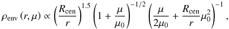 (1)where μ ≡ cosθ, Rcen the centrifugal radius, and r the spherical radius. The centrifugal radius defines the region in which the material no longer flows radially and enters the disk. Two centrifugal radii of Rcen = 50 AU and 200 AU were explored. The low Rcen corresponds to the small Keplerian disk toward L1527 (Ohashi et al. 2014), while the high Rcen corresponds to the maximum disk radius (~180 AU) observed toward a class 0 embedded low-mass young stellar objects (YSO; Murillo et al. 2013). The two cases explore the effect of mass concentration in the inner envelope on water emission. For a given centrifugal radius, a particle follows a parabolic motion given by
  (2)where μ0 satisfies the condition above at every r and μ. The outer radius of the envelope is fixed at rout = 104 AU with an inner radius of 0.1 AU, where the dust typically sublimates (assuming a dust sublimation temperature, Tsub, between 1500–2000 K).
An outflow cavity is then carved out from the envelope density structure at μ0> 0.95. Following Crapsi et al. (2008), the density inside the cavity is equal to that of the densities at rout. This creates a conical outflow with an aperture of 30° at large radii (semi-aperture of 15°). For a 1 M⊙ envelope, gas densities of ~104 cm-3 fill the envelope cavity, which is consistent with those observed toward YSOs (e.g., Bachiller & Tafalla 1999; Whitney et al. 2003).
A flared accretion disk is added to the envelope density structure. The density within the disk follows the power-law dependence radially and has a Gaussian distribution vertically in z as expected from a hydrostatic disk. The flared disk densities (Shakura & Sunyaev 1973; Pringle 1981; Hartmann et al. 1998; Williams & Cieza 2011) are described by ![Mathematical equation: \begin{equation} \rho_{\rm disk} \left ( R, z \right ) = \frac{\Sigma_0 \times (R/R_{\rm disk} )^{-1} }{\sqrt{2 \pi} H(R)} \exp \left [ -\frac{1}{2} \left (\frac{z}{H(R)} \right )^2 \right ], \end{equation}](/articles/aa/full_html/2015/10/aa25966-15/aa25966-15-eq54.png) (3)where the scale height H is fixed to 0.2 AU (H0) at 1 AU (R0), Rdisk the disk radius, and R the cylindrical radius. The radial dependence of the scale height is H(R) = RH0/R0 (R/R0)2 / 7 (Chiang & Goldreich 1997). Finally, the densities are scaled by a constant factor Σ0 such that the total disk mass within Rdisk (R<Rdisk) is equal to the values in Table 1 and distributed within Rdisk. In the case of Rcen = 50 AU flattened envelopes, only Rdisk = 50 AU models are considered. The total gas density in the model is ρ = ρdisk + ρenv with a gas-to-dust mass ratio of 100.
(3)where the scale height H is fixed to 0.2 AU (H0) at 1 AU (R0), Rdisk the disk radius, and R the cylindrical radius. The radial dependence of the scale height is H(R) = RH0/R0 (R/R0)2 / 7 (Chiang & Goldreich 1997). Finally, the densities are scaled by a constant factor Σ0 such that the total disk mass within Rdisk (R<Rdisk) is equal to the values in Table 1 and distributed within Rdisk. In the case of Rcen = 50 AU flattened envelopes, only Rdisk = 50 AU models are considered. The total gas density in the model is ρ = ρdisk + ρenv with a gas-to-dust mass ratio of 100.
2.2. Temperature structure and heating terms
The three-dimensional dust continuum radiative transfer code RADMC-3D1 was used to calculate the dust temperature structure. A central star with temperature of 4000 K (a typically inferred effective temperature of class I protostars; White & Hillenbrand 2004; Nisini et al. 2005) characterized by L⋆ 1, 5, and 15 L⊙ was adopted. An accurate dust temperature structure of the disk is crucial in determining the location where the various volatiles thermally desorb from the grain. This is computationally challenging for a massive optically thick disk as we modeled here (see Min et al. 2009). Thus, we separated the dust temperature calculations due to the central star irradiation (passive) from the viscous heating treatment (see Fig. 1). The former was determined by RADMC3D considering a black body central star as listed in Table 1.
 |
Fig. 1 Schematic showing the calculation of the thermal structure of the disk by combining both the RADMC3D Monte Carlo simulation and the diffusion equation. The Monte Carlo simulation calculates the temperature structure due to the irradiation (Tirr) from a central star, while the diffusion equation is used to solve the temperature structure at high optical depths (τR> 1 where τR is the Rosseland mean optical depth) as indicated by the red line. This high optical depth region typically starts below the disk surface. The outflow wall, warm inner envelope (Tdust> 100 K and r< 500 AU), and photodissociation region are indicated. |
 |
Fig. 2 Total luminosity (Ltot = L⋆ + Ldisk + Lin) as a function of accretion rates for different stellar luminosities. |
An actively accreting disk provides additional heating (Ldisk) from the loss of mechanical energy as the gas is viscously transported inward. The steady-state accretion rate is typically between 10-5 − 10-7M⊙ yr-1 (Hueso & Guillot 2005). However, episodic accretion events such as those simulated by Vorobyov (2009) can have transient spikes with an accretion rate of up to 10-4M⊙ yr-1. Thus, stellar accretion rates between 10-9–10-4M⊙ yr-1 were adopted, following the α disk formalism (Shakura & Sunyaev 1973; Williams & Cieza 2011). The viscous heating rate per volume is given by 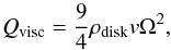 (4)where v = αcsH is the α-dependent turbulent viscosity parameter, cs the sound speed of the gas, and Ω the Keplerian angular velocity. At steady state, the viscosity is related to the disk mass and the accretion rate through (Lodato 2008)
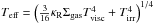
  (5)To explore the degree of heating, the viscosity term v was varied for the explored accretion rates at a fixed disk mass (∝Σ). The effective temperature (Tvisc) associated with the energy released at the inner radius assuming a hydrostatic disk is
 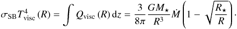 (6)This was obtained by integrating the viscous heating terms vertically at all radii. Furthermore, Tvisc is the effective temperature of the disk at the optically thin photosphere without the addition of stellar irradiation. However, the midplane temperature of an active disk is proportional to the vertical optical depth (Hubeny 1990):
  with κR the Rosseland mean opacity which results in higher midplane temperatures. This method is similar to that of Kennedy & Kenyon (2008) and Hueso & Guillot (2005) in the optically thick regime. We note that the heating from an accreting disk is caused by the dissipation of energy from both gas and dust. To account for the irradiation from the accreting disk, Ldisk = ∫πσTvisc(R)4RdR was added to the central luminosity L⋆ by determining its black body spectrum at Tvisc at all radii of the disk. For the case of high accretion rates, it is expected that the accretion proceeds onto the star since a gaseous disk is present within the dust sublimation radius. The total luminosity from the inner disk is
  . Thus, the final irradiating central source Ltot is the combined heating from the central star, the dusty disk, and the inner gaseous disk: Ltot = L⋆ + Ldisk + Lin. Figure 2 shows the relation between Ltot and Ṁ for different L⋆ values.
The following steps were taken to calculate the dust temperature of an accreting embedded disk.
-
Monte Carlo dust continuum radiative transfer was used tosimulate the photon propagation to determine the passivelyheated dust temperature structure (Tirr) due to total luminosity (Ltot). Thedust opacities of Crapsiet al. (2008) were adopted; they arecomposed of a distribution of ice-coated silicates and graphitegrains. The removal of ices from the grain at Tdust> 100 K doesnot strongly alter the dust temperature structure.
-
Viscous heating was added to the region of the disk where the Rosseland mean optical depth τR> 1. This was made by fixing the midplane temperatures to
 . The vertical dust temperature structure was calculated using the diffusion approximation ∇D∇T4 = 0 bounded by Tirr at the surface as obtained from the previous step and Tmid at the midplane where D = (3ρdustκR)-1. The diffusion was performed only within the τR> 1 regions. This calculation was repeated a few times until it converged. Convergence was obtained when there was no longer any change in the the τR> 1 region.
The snowlines of protoplanetary disks without an envelope were obtained and compared with Min et al. (2011) to verify our approach (see Fig. A.1). Using this formulation, the differences in predicted water snowlines are typically within 2 AU at low accretion rates and lower at high accretion rates.
2.3. Molecular abundances
The aim of this paper is to calculate the 2D snowlines or snow-surfaces for CO, CO2, and H2O in embedded disks. The region in which these volatiles freeze out onto grains depends on the temperature and density structure (e.g., Meijerink et al. 2009). At steady state, the rate at which the molecule is adsorbed on the grain is balanced by the thermal desorption rate. We adopted a dust number density ndust = 10-12nH (Visser et al. 2009) with adust = 0.1 μm as the effective grain size. The number density of solids of species X (see also Fig. B.1) is simply given by 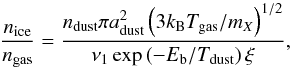 (7)where Tgas is gas temperature, Tdust is dust temperature, and mX is the mass of species X. The first-order pre-exponential factor, ν1, was calculated from the binding energy, Eb (Hasegawa et al. 1992; Walsh et al. 2010)
  (8)with the number of binding sites per surface area, Nss, was taken to be 8 × 1014 cm-2 following Visser et al. (2011). A dimensionless factor
  was used to switch between zeroth-order to first-order desorption when the ice thickness is less than a monolayer. The properties for each molecule are given in Table 2 along with the calculated pre-exponential factor ν1. These binding energies assume pure ices. The typical timescales for adsorption are 4 − 6 × 10³ yr at temperature of 50 K and number densities (nH2) of 106 cm-3. This implies that the steady-state assumption is not valid at lower densities that are present in the large-scale envelope (r> 1000 AU) where the freeze-out timescales become longer than the lifetime of the core (e.g., Jørgensen et al. 2005). On the other hand, we here focus on the gas phase abundances at small-scale r ≤ 100 AU where the number densities are nH2> 106 cm-3. Photodesorption can be ignored at such high densities and within the disk, but it may be important at the disk’s surface and along the outflow cavity wall. Since the water vapor will also be rapidly photodissociated in these locations, these regions are not major water reservoirs (see Fig. 1). To approximate this region, water was assumed to be absent within a region that is characterized by AV ≤ 3 or NH ≤ 6 × 1021 cm-2. A more detailed gas phase abundance structure through a chemical network will be explored in the future.
Molecular parameters to calculate ℛdes as tabulated in Burke & Brown (2010).
3. Results
3.1. Thermal structure of an actively accreting embedded disk
The locations where various molecules can thermally desorb from the dust grains depend on the temperature structure of the disk. Irradiated disks have a warm upper layer with a cooler midplane. Figure 3 (red dashed lines) shows the midplane (bottom) and vertical temperature at a number of radii (top) for an embedded disk passively irradiated by a 1 L⊙ central source. Here, we present the results for a 0.1 M⊙ disk embedded in a 1 M⊙ envelope whose Rcen is 200 AU (Fig. 3 top). These canonical parameters are highlighted in Table 1.
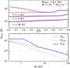 |
Fig. 3 Midplane radial (bottom) and vertical temperatures (top) at 1, 5, and 25 AU for an embedded 0.1 M⊙ disk and an accretion rate of 10-5M⊙ yr-1 irradiated by L⋆ = 1 L⊙. The red dashed (bottom) and solid (top) lines indicate the thermal structure of a passively irradiated disk (Tirr) calculated by the Monte Carlo simulation. The blue solid lines indicate the temperatures including the viscous heating ( |
 |
Fig. 4 Dust temperature structure in the inner 44 AU for three different accretion rates for a 0.1M⊙ disk embedded in a 1 M⊙ envelope. A 1 L⊙ central heating source is adopted for these models. The disk is oriented horizontally, while the outflow cavity is oriented vertically. The three different lines indicate 160 (dashed-dotted), 100 (dashed), and 50 (solid white) K contours, which are important for the water snowlines (see Fig. B.1). |
The dust temperatures of an embedded actively accreting disk are indicated by the blue lines in Fig. 3. The dotted line shows the viscous temperature (Tvisc) as expected at the photosphere (optically thin), while the solid blue lines show the effective dust temperature corrected for the optical depth and passive irradiation. As previously found, the addition of viscous heating can raise the temperatures in the inner few AU to >1000 K (e.g., Calvet et al. 1991; D’Alessio et al. 1997; Davis 2005). The disk temperature is above the water sublimation temperature out to R ~ 30 AU for an accretion rate of 10-5M⊙ yr-1. Because of the R-3 dependence of Tvisc (see Eq. (6)), the viscous heating is dominant in the inner few AU as indicated in Fig. 3 (bottom). Consequently, the passive irradiation due to the central luminosity (L⋆) dominates the temperatures along the disk photosphere and the outflow cavity wall, while the viscous dissipation dominates the heating deep within the disk. These effects can be seen in the 2D dust temperature structure in the inner ~40 AU shown in Fig. 4 for three different accretion rates. For Ṁ ≳ 10-5M⊙ yr-1, panels show the vertical temperature inversions.
The dust temperature structure is also compared with a disk with and without an envelope whose Rcen is 50 AU in Fig. 5. The difference is small in the inner disk and primarily lies at large radii (R> 1 AU) where the midplane temperature structure (Tmid ∝ Σ) is weakly affected by the adopted envelope model. The temperature structure of the embedded disk model slightly depends on the adopted envelope model. Most importantly, at R = 5 and 150 AU, the embedded disk model with Rcen = 50 AU is warmer than the other two models. This is mainly due to the mass distribution in the inner 100 AU. Overall, however, the differences are small (see also D’Alessio et al. 1997) and, for our purposes, it is sufficient to fix the envelope mass to 1 M⊙ to assess the overall temperature structure of an embedded actively accreting disk. The effects are further discussed in Sect. 3.4. However, the difference at larger radii is sufficient to affect the dominant phase of CO2 and CO.
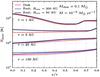 |
Fig. 5 Comparison of the vertical temperature structure at 1, 5, 25, and 150 AU between a protoplanetary disk (red) and embedded disks (blue and black). The difference between the two embedded disk models is the centrifugal radius Rcen = 50 AU (black) versus 200 AU (blue). The envelope mass is 1 M⊙ for the embedded disk model. |
3.2. Water snowline
 |
Fig. 6 Midplane water snowlines as function of accretion rates and disk mass for a 200 AU embedded disk with Rcen = 200 AU. The different lines indicate the snowline dependence on disk mass at a fixed stellar luminosity and envelope mass. |
Using the obtained dust temperatures, the gas and ice number densities were calculated at each cell. To determine the snowline, the total available water mass was computed by adopting a water abundance of 10-4 with respect to H2. The total available mass was then multiplied by the gas fraction to determine the total water-vapor mass. A minimum gas water abundance of 10-9 with respect to H2 was used. The snowline is defined as the radius at which 50% of the total available water has frozen onto the grains (Mgas/Mice = 0.5; e.g., Min et al. 2011). This typically occurs at ~160 K in the high-density regions (nH ~ 1014 cm-3, see dashed line in Fig. 4).
Figure 6 presents the midplane snowline radius as a function of accretion rate. In the absence of accretion heating, the water snowline is located at ~3 AU. This does not strongly depend on the accretion rate until a value of Ṁ> 10-7M⊙yr-1 is reached. The highest water snowline is located at 55 AU for an accretion rate of 10-4M⊙ yr-1. Although the effective disk midplane temperature depends on the disk mass, it does not strongly affect the water snowline location. It is located at only slightly smaller radius for a less massive disk (0.05 M⊙) as indicated in Fig. 6.
The steep increase of the water snowline at high accretion rates can be understood by comparing the stellar luminosity and the accretion luminosity. For the canonical values that are indicated in Table 1, the irradiating central luminosity is 1 L⊙. The accretion luminosity is estimated by integrating Eq. (6) radially over the active disk between 0.1 and 200 AU, in this case, and is approximately Lacc ~ 0.5 × GM⋆Ṁ/Rin. Thus, the accretion luminosity is equal to that of the central star for Ṁ ~ 3 × 10⁻⁶M⊙ yr-1. The addition of the accretion onto the star due to the gaseous inner disk provides an additional ~10 L⊙ luminosity at the given accretion rate. Thus, the accretion luminosity starts to contribute to the heating at Ṁ ≳ 10-7M⊙ yr-1 for the adopted parameters (see Fig. 2).
 |
Fig. 7 Locations of gas phase volatiles in the 0.1 M⊙ disk embedded in a 1 M⊙ envelope. The different colors indicate the different regimes where various volatiles are found in the gas phase: blue (H2O, CO2, and CO), red (only CO2 and CO), and green (only CO). The accretion rate is indicated at the top. The arrows are indicating three different regions as indicated in Fig. 1: water photo-dissociation region defined by AV = 3, warm inner envelope, and the disk surface (yellow line assuming Tgas = Tdust). |
The observable water emission depends on the water vapor column density. The water vapor column extends farther than the snowline due to the vertical gradient in water vapor abundance. The available water is rapidly frozen out onto dust grains beyond the snowline. To determine whether the location of the snowline is within the disk or not, the hydrostatic disk surface was determined through H = cs/ ΩK, where 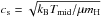 is the sound speed and ΩK the Keplerian angular frequency. This is the approximated regime where the gas should be in Keplerian motion. For a 1 L⊙ central star, most of the water emission arises from the warm inner envelope (sometimes also called the “hot core”) above the hydrostatic disk surface as shown by the yellow line in Fig. 7 if a constant water abundance of 10-4 with respect to H2 is adopted. The blue shaded region in Fig. 7 indicates where water vapor is dominant, some water vapor (<50% in mass) is still present within the inner few AU of the red regions (≲30 AU). Water vapor is also present along the cavity walls as indicated by the two purple lines in Fig. 7, but these regions have low extinctions (Av< 3), which allows for the photodissociation of water.
3.3. CO and CO2 snowlines
 |
Fig. 8 Left: midplane CO2 snowlines as a function of accretion rates and disk mass for a 200 AU disk. Right: midplane CO snowlines as a function of accretion rates for the same disk. The different colors indicate the snowline dependence on disk mass at a fixed stellar luminosity (1 L⊙) and envelope mass (1 M⊙). |
Pure CO2 and CO ices thermally desorb over a narrow range of dust temperatures between 40–80 K and 15–30 K, respectively, depending on the density (see Fig. B.1). As a result of their lower binding energies relative to water, CO and CO2 are in the gas phase within a large part of the embedded disk. The CO2 snowline is between 20–250 AU for 10-9–10-4M⊙ yr-1 accretion rates (see Fig. 8). Thus, the entire disk including the midplane lacks CO2 ice for highly acccreting embedded disks (Ṁ ~ 10-4M⊙ yr-1). The steep rise of the CO2 snowline at high accretion rates is similar to that of water as shown in Fig. 6.
Since the adopted binding energy of CO to the dust grain is the least with 855 K, CO largely remains in the gas phase within the disk for L⋆ ≥ 1 L⊙ independently of the accretion rate (see Fig. 8 right). At low accretion rates, the snowline is located at ~150 AU at the midplane, indicating the presence of CO ice between 150 to 200 AU within the disk. However, the bulk of CO within the disk remains in the gas phase as shown in Fig. 7. A smaller disk during the embedded phase would lead to stronger envelope irradiation (e.g., D’Alessio et al. 1997), and, consequently, CO is not frozen out within the disk. A sufficiently large and massive disk (Mdisk> 0.2 M⊙ irradiated by a 1 L⊙ star) could contain a higher percentage of CO ice at large radii. This is simply due to the increase of optical depth and, thus, lower dust temperatures at large radii.
3.4. Dependence on stellar, disk, and envelope properties
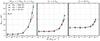 |
Fig. 9 Midplane water snowline as a function of stellar luminosity, accretion rate, and disk radius. The envelope mass is fixed at 1 M⊙ with a disk mass of 0.1 M⊙ and Rcen = 200 AU. The different panels show the water snowline as a function of stellar luminosity: 1 L⊙ (left), 5 L⊙ (center), and 15 L⊙ (right). The different colors indicate the disk radius: 200 AU (blue), 100 AU (green), and 50 AU (red). |
Previous sections presented the vapor content for a 0.1 M⊙ embedded disk surrounded by a 1 M⊙ envelope with Rcen = 200 AU that is being irradiated by a 1 L⊙ central star (T⋆ = 4000 K, R⋆ = 2.1 R⊙) as highlighted in Table 1. As noted in Sect. 2.2, the effective midplane temperature (Teff) depends on the disk mass, but an increasing disk mass only leads to a small change in the water snowline as shown in Fig. 6. Figure 7 shows that the water vapor can be either within the disk or within the warm inner envelope. This section explores how the vapor content depends on disk radius and central luminosity for fixed envelope and disk (0.1 M⊙) masses.
Figure 9 presents the locations of water snowline as a function of accretion rate, luminosity, and disk radius. For a fixed disk structure, a factor of 5 increase in L⋆ shifts the midplane water snowline by a factor of ~2 from ~4 AU (1 L⊙) to ~10 AU (10 L⊙) at low accretion rates (Ṁ< 10-7M⊙ yr-1). A factor of 15 increase in L⋆ yields a factor of ~4 increase in the location at the water snowline. The stellar luminosity L⋆ is defined by the stellar radius, while the accretion dependent total luminosity Ltot that is irradiating the system is shown in Fig. 2. For high accretion rates (Ṁ ≳ 10-5M⊙ yr-1), the water snowline decreases as L⋆ increases. This can be explained as due to the fact that Ltot decreases as L⋆ increases at high accretions because R⋆ increases, which in turn decreases the luminosity that is provided by the inner gaseous disk. Thus, if the stellar accretion rates are low (L⋆>Lacc), the stellar luminosity is the parameter to be varied to increase the water snowline. However, the water snowline can be up to 50–60 AU if the stellar luminosity is low (small stellar radius) and the stellar accretion rate is high.
The CO2 midplane snowline shows a similar behavior as the water snowline (Fig. B.2) as a function of stellar luminosity and accretion rates. It is in the gas phase at R> 40 AU for L⋆ ≥ 5 L⊙, which is an increase of a factor of 2 in terms of snowline location with respect to the canonical value of L⋆ = 1 L⊙. As CO is already largely in the gas phase for the canonical values, a small increase of the stellar luminosity results in the lack of a CO snowline within the disk (Fig. B.3).
Another parameter that affects the total energy input into the embedded system is the disk radius. The total accretion luminosity that is being added depends on the disk radius, which is the region where the disk accretion energy is being integrated. A decreasing disk radius leads to a decreasing accretion luminosity. This only affects the midplane water snowline in the case of L⋆ = 1L⊙ (see Fig. 9). In this case, the difference is seen only for high stellar accretion rates where the accretion luminosity (Ldisk + Lin) starts to be the dominant heating source. The midplane water snowline decreases from ~55 AU to ~38 AU as the disk radius decreases from 200 AU to 50 AU. Thus, an increasing stellar luminosity (L⋆) has a greater effect on the midplane water snowline. This leads to an increase of water vapor in the warm inner envelope (see Fig. 7) for low stellar accretion rates (Ṁ< 10-5M⊙ yr-1). However, if L⋆> 1 L⊙, the disk radius does not affect the location of the midplane water snowline even for high accretion rates (Ṁ> 10-5M⊙ yr-1) since the total luminosity is dominated by the stellar luminosity. The CO2 snowline, on the other hand, shows a stronger dependence on the disk radius than that of water. For the high stellar luminosity case L⋆ = 15 L⊙, the CO2 snowline increases from 40 AU to 80 AU as the disk radius (Rdisk) increases from 50 AU to 200 AU. This can be explained by the density distribution in the inner region. For a small disk, the dust temperature is low enough at large radii such that CO2 can exist in the solid phase. However, as the size of the disk increases, the overall density at similar radii decreases, which results in lower optical depth and, as consequence, higher dust temperatures at large radii. The disk radius parameter seems to be more important for the CO2 snowline than for the water snowline.
The main parameter for the envelope in our setup is the centrifugal radius. For the canonical value of Rcen = 200 AU, the mass of the disk can be distributed between 50, 100, or 200 AU. The disk radius Rdisk is where the disk ends, and it can be smaller than Rcen. Here, the effects of a flattened envelope as defined by the centrifugal radius Rcen are presented. A smaller centrifugal radius results in a hotter inner disk (see Fig. 5). However, the affected regions correspond to the regions within the disk where dust temperatures are already >100 K. Thus, we find that there is no change in the water snowline for a more flattened envelope structure (Rcen = 50 AU instead of 200 AU). More volatile species such as CO2 and CO are affected by the flattened envelope structure, however. The CO2 snowline is confined within the inner 40 AU for Ṁ ≤ 10-5M⊙ yr-1. At higher accretion rates, the combination of a warm disk and low envelope densities at R> 50 AU for the Rcen = 50 AU model results in a warm envelope where CO2 is largely in the gas phase up to 400–500 AU along the midplane, while it is ~200 AU in the canonical model. The snowline of CO is already at 400 AU for an Rcen = 50 AU envelope model at low accretion rates instead of ~200–300 AU in the case of Rcen = 200 AU envelope. Thus, we find that the inner envelope and disk physical structure to be important in determining the location of snowlines of various volatiles. These parameters are largely unknown as yet for deeply embedded YSOs.
4. Discussion
4.1. Comparison with accreting protoplanetary disk models
In the absence of an envelope, similar stellar parameters and an accretion rate of 10-8M⊙ yr-1 lead to the midplane water snowline located at ~1 AU (e.g., Sasselov & Lecar 2000). Lecar et al. (2006) suggested that the snowline can move out by increasing the accretion rate, disk mass, and the dust opacities. The differences between the derived snowlines in the literature are unlikely to be due to the differences in radiative transfer treatment, which has been compared in Min et al. (2011). As an example, Garaud & Lin (2007) derived similar water snowlines to that of Min et al. (2011; 1 AU vs. 2 AU) at similar accretion rates using different methods in deriving the dust temperatures and different opacities. The latter model takes into account the detailed 2D vertical structure of the disk and dust sublimation front. As Min et al. (2011) showed, most of the differences are due to the adopted dust opacities. Our value is ~1 AU higher than the values tabulated in Min et al. (2011) for similar parameters. Furthermore, most of the previous studies adopted the minimum mass solar nebula (MMSN) model, where Σ ∝ R-1.5 instead of the R-1 2D parametric disk structure used in this paper (see, e.g., Andrews et al. 2009). Previous snowlines or snow surfaces studies did not take the flattened envelope into account.
Previous studies have found that the water snowlines in the more evolved disks decrease with decreasing accretion rates (e.g., Davis 2005; Garaud & Lin 2007; Min et al. 2011). This has been reproduced in Fig. A.1. However, if the disk structure is related to its stellar accretion rate such as adopted in Garaud & Lin (2007), the water snowline increases to a constant value at ~2 AU for very low accretion rates (Ṁ ≲ 10-10M⊙ yr-1). This is due to the disk becoming more optically thin, which in turn allows for stellar photons to penetrate deeper radially into the disk. In this paper, the disk structure was fixed while the stellar accretion rate was varied. However, the envelope provides a blanket where the disk can stay relatively warm. Thus, even though the disk structure is fixed, the snowline stays at a fixed radius for decreasing stellar accretion rates.
Taking the envelope into account, for the same accretion rate of 10-8M⊙ yr-1, our water snowline is at ~3 AU for embedded disks compared to 1–2 AU without an envelope. The presence of the envelope does not strongly affect the midplane temperature at regions close 100 K, as shown in Fig. 5. Thus, it does not significantly modify the water snowline. However, it does affect the CO2 and CO snowlines, since the 40 K region shifts inward under the presence of an envelope depending on the centrifugal radius.
4.2. Caveats
 |
Fig. 10 Left: beam-averaged water (H |
The effect of convection in the vertical direction is not included in this study. It is typically found to be important in the case of high accretion rates (Ṁ> 10-6M⊙ yr-1, D’Alessio et al. 1998; Min et al. 2011). Convection is found to cool the midplane temperatures at Tdust> 500 K. Thus, this should not affect the water (100–160 K), CO2 (~50 K) and CO (~20 K) snowlines as their sublimation temperatures are much lower than 500 K.
Under the assumption of the steady-state accretion disk model, the typical values of α are found to be >1 for an accretion rate of Ṁ = 10-4M⊙ yr-1. This is significantly higher than that expected from magnetorotational instability (MRI) driven accretion in an MHD disk (α = 0.01, Balbus & Hawley 1998). King et al. (2007) indicated that α could be ~0.4 for thin disks around compact systems. These high α values in our models are obtained because we fixed the density distribution at a high accretion rate (Ṁ> 10-5M⊙ yr-1). In reality, such a disk is unphysical. However, this is only encountered for the highest accretion rate of 10-4M⊙ yr-1 that occurs for a very short time. In principle, this can be avoided by iterating the disk structure to ensure that the hydrostatic conditions are satisfied. However, this paper explores the effect of the adopted accretion rates and disk masses for a given fixed set of parameters. Self-consistent models including gas opacities and multiple dust species should be explored in the future.
4.3. Comparison with observations
The extent of the observed spatially resolved water emission toward low-mass embedded YSOs is between 25–90 AU (Jørgensen & van Dishoeck 2010; Persson et al. 2012, 2014). The water snowline is confined to within the inner 40 AU for the cases of the envelope models whose centrifugal radius is 50 AU. In such models, we set the disk to not extend beyond 50 AU. The water snowline was only increased when the centrifugal radius of the envelope was larger than 50 AU, in which case the water snowline can extend up to 55 AU if the stellar luminosity is low (L⋆ = 1 L⊙). Thus, our results indicate that most of the water emission at R< 50 AU would originate from the combined disk and warm inner envelope (see Fig. 7).
Through the combined modeling of the continuum spectral energy distribution and submm continuum images, the envelope masses toward the observed embedded sources (NGC 1333 IRAS 2A, IRAS 4A, and IRAS 4B) are found to be between 3–5 M⊙ (Kristensen et al. 2012), somewhat higher than our canonical value. On the other hand, all three sources are binaries (e.g., Jørgensen et al. 2004, 2007), therefore it is likely that the effective envelope mass that affects the disk physical structure is lower than the above values. Therefore, the envelope masses were kept fixed at 1 M⊙.
The amount of water vapor in the embedded disk models can be compared to the observed optically thin millimeter water emission toward deeply embedded YSOs. Thermalized HO emission at 203.4 GHz (31,3 − 22,0) is calculated using the following equation  where Aul is the Einstein A coefficient of the 203 GHz transition is 4.5 × 10⁻⁷ s-1, Tex is taken to be 150 K, Eu = 204 K is the upper energy level, and
  is the temperature-dependent partition function adopted form the HITRAN database (Rothman et al. 2009). The beam-averaged column density (
 ) is taken from within 50 AU radius with 16O:18O isotopic ratio of 540 (Wilson & Rood 1994). The line profile is assumed to be Gaussian with a FWHM (Δυ) = 1–4 km s-1 as observed toward the three embedded sources reported by Persson et al. (2014).
Figure 10 (left) presents the mean H O gas column density of the simulated embedded disks as a function of accretion rate for different disk masses and stellar luminosities. The mean column density rises sharply for Ṁ> 10-7M⊙ yr-1 as expected for a 1 L⊙ stellar luminosity, while the sharp rise occurs at Ṁ> 10-6M⊙ for a 5 L⊙ irradiating source. The typical line optical depth at the line center (υ = 0 km s-1) can be τυ = 0 ≥ 1. The typical average column densities of water between 50 AU to 1000 AU are >4 orders of magnitude lower than the values within 50 AU as presented in Fig. 10. Thus, the water present within 50 AU dominates the total water mass for the adopted models.
The expected integrated HO 31,3–22,0 (203.4 GHz) line flux densities for the embedded disk models are also shown in Fig. 10 (right). The integrated line flux densities ( ) were calculated with a Gaussian line profile with Δv = 1 km s-1 (1.06 Sυ = 0 × Δυ, where Sυ = 0 is the peak flux density at line center) as observed toward NGC 1333-IRAS 4B (Persson et al. 2014). The observed line widths toward IRAS 2A and IRAS 4A are 4 and 3 km s-1, respectively. Increasing Δυ slightly increases the model integrated line flux densities because the line is slightly optically thick.
The predicted integrated line flux densities from actively accreting embedded disk models are consistent with that observed toward NGC 1333 IRAS 4B if Md ≤ 0.2 M⊙ with Ṁ ≳ 6 × 10⁻⁷M⊙ yr-1 for L⋆ = 1 L⊙. Jørgensen et al. (2009) estimated from the continuum that the disk mass is ~0.2 M⊙, which is consistent with our results. Decreasing the disk mass implies that a higher accretion rate is required to reproduce the observed water emission. A higher accretion rate (~1 × 10⁻⁵M⊙ yr-1) with lower disk mass is also consistent with the observed extent of water emission at ~20 AU. A similar conclusion is reached for the case of IRAS 4A, whose disk is estimated to be ~0.5 M⊙ (Jørgensen et al. 2009). Since the bolometric luminosities toward NGC 1333 IRAS 4A and IRAS 4B are a factor of 4–9 higher than the adopted central luminosity (L⋆), a model with a factor of 2 lower mass disk can also reproduce the observed flux density with accretion rates ~10-5M⊙ yr-1. The total luminosity generated by such embedded systems would be similar to the observed bolometric luminosities. With such a lower mass disk, the warm inner envelope is the dominant source of emission instead of the Keplerian disk. This implies that it would be difficult to observe the Keplerian motion of the disk from HO lines.
IRAS 2A shows stronger integrated line emission (~1 Jy km s-1) relative to the other two sources and extending up to 90 AU radius. As pointed out above, a disk cannot be responsible for any warm water emission at R> 50 AU. Furthermore, Brinch et al. (2009) estimated that the disk is at most ~0.05M⊙, which lowers the expected disk contribution to the observed water emission (see also Jørgensen et al. 2009 and Maret et al. 2014). There are two possible scenarios that can explain such a high water emission: a more luminous star (L⋆> 10 L⊙) or a high stellar accretion rate (~10-5M⊙ yr-1). Both solutions result in total luminosity Ltot comparable to the observed bolometric luminosity of IRAS 2A (Lbol = 35.7 L⊙, Karska et al. 2013). In either case, most of the water emission arises from the warm inner envelope with negligible disk contribution.
The best cases for an actively accreting embedded disk scenario are IRAS 4A and IRAS 4B. More detailed modeling of their physical structure at <100 AU radius is required to further constrain the relation between infall (envelope to disk) and stellar accretion rate (disk to star). Mottram et al. (2013) suggests that the infall rate from the large-scale envelope toward IRAS 4A at 1000 AU to be ~10-4M⊙ yr-1. For disk masses between 0.2–0.5 M⊙, the disk must also process the material at similar rate (within a factor of 10), which is consistent with the models presented here.
Observational perspectives.
Future spatially and spectrally resolved ALMA observations of optically thin water (HO) and deuterated water (HDO) lines may be able to differentiate these models. The spatially resolved data can provide the extent of the water emission. The comparison between the source’s bolometric luminosity and the extent of the water emission can provide limits on the stellar accretion rate. A low bolometric luminosity source cannot have a water emission originating from the disk farther than a few AU. Furthermore, the velocity information within the inner 50 AU radius can help in distinguishing between the disk and the infalling envelope (see, e.g., Harsono et al. 2015).
4.4. Connecting to the young solar nebula
It is thought that the disk out of which the solar system formed (the solar nebula) was initially hot enough to vaporize all material inherited from the collapsing cloud into atoms, then turn them into solids according to a condensation sequence as the nebula cools (Lewis 1974; Grossman & Larimer 1974). Evidence for energetic processing and subsequent condensation comes from meteoritic data collected in the inner solar system (see Kerridge & Matthews 1988; Scott 2007; Apai & Lauretta 2010, for reviews). After the refractory phases have formed, more volatile species such as ices can also condense at larger distances from the young Sun, with ice composition depending on the temperature and pressure as well as the elemental abundance ratios (e.g., Lunine et al. 1991; Owen & Bar-Nun 1993; Mousis et al. 2009; Pontoppidan et al. 2014). Using cooling curves appropriate for the solar nebula, models show that various ices including H2O, CH3OH, NH3, and CO2 ice form by condensation out of warm gas out to at least 20 AU (Mousis et al. 2012; Marboeuf et al. 2014). This condensation process is important to explain the composition of volatiles in the atmospheres of solar-system giant planets and comets.
Where and when does this heating and condensation in the disk actually occur? The above processes are usually discussed in the context of protoplanetary disks where the envelope has dissipated and where the water snowline is eventually at a few AU once the disk has cooled. However, neither observations nor models of disks around solar-mass T Tauri stars show any evidence that disks are as warm as required above to have condensation occurring out to 20 AU (Beckwith et al. 1990; D’Alessio et al. 1998; Dullemond et al. 2007). Furthermore, observations suggest that significant grain growth has occurred (Testi et al. 2014) and disk inhomogeneities due to protoplanets are present in such evolved disks (e.g., Quanz et al. 2013). This further violates the assumption that the physical structure of an evolved disk can be used to study the young solar nebula. The results from this paper indicate that instead such a hot disk may be more common in the early stages of disk formation during the embedded phase (Menv>Mdisk). The disk is then expected to have high accretion rates providing the necessary additional heating. Furthermore, the high accretion rates necessary to push the midplane snowlines to 20 AU and beyond tend to occur for only a short time (e.g., Vorobyov 2009). Most volatiles including H2O, CH3OH, CO2, and CO presented here will then be in the gas-phase within this 20–30 AU radius through sublimation of ices. Shortly after, the volatiles recondense as the accretion rate decreases, with the process controlled by the freeze-out timescale. The inclusion of the gas motions (radially and vertically) and kinetics does not allow for instantaneous re-condensation, thus some gas-phase volatiles are expected to remain near the snowline (Lewis & Prinn 1980; Ciesla & Cuzzi 2006).
A related question is whether the volatiles that are incorporated into planetesimals and eventually planets and icy bodies in the critical 5–30 AU zone are then inherited or reset during the disk formation process. The material is defined to be inherited if the simple and complex ices that have been built up in the envelope survive the voyage to the planetary and cometary forming zones. Evolutionary models by Visser et al. (2009) and Visser et al. (2011) suggest that strongly bound ices such as H2O are largely pristine interstellar ices in the outer disk, whereas more volatile species can have sublimated, recondensed, and reprocessed several times on their way to the inner disk. However, these models have not included internal viscous dissipation as an additional heating source. A warmer early disk can facilitate ice evolution and formation of complex organic molecules in the temperature regime between 20–40 K (Garrod et al. 2008; Nomura et al. 2009; Walsh et al. 2014; Drozdovskaya et al. 2014). Our results including the accretion heating indicate that significant ice reprocessing may occur out to larger radii than thought before, well in the comet formation zone. Such a reset scenario is supported by the meteoritic data from the inner few AU, but the fraction of material that is reset at larger radii is still unknown (e.g., Pontoppidan et al. 2014). If some of the icy grains are incorporated into km-sized bodies (planetesimals) immediately following disk formation, a larger fraction of the material could still remain pristine.
5. Summary and conclusions
Two-dimensional embedded disk models were presented to investigate the location of the snowlines of H2O, CO2, and CO. The dust temperature structure was calculated using the 3D dust radiative transfer code RADMC3D with a central heating source (L⋆ + Lvisc + Lin). An additional heating term from an actively accreting disk was added through a diffusion approximation. The main parameters we explored here are L⋆, centrifugal radius, disk radius, disk mass, and stellar accretion rate. In addition, the extent of the snowline and optically thin water emission were compared with observations toward three deeply embedded low-mass YSOs. The following lists our main results.
-
The presence of an envelope serves as a blanket for the disk suchthat the dust temperature within the inner few AUstays relatively warm for the adopted disk parameters. Theadopted centrifugal radius affects the temperature structure ofthe disk since the effective midplane temperature depends onthe optical depth. An envelope with a smaller centrifugal radiusdistributes more mass in the inner 100 AU than anenvelope with a higher centrifugal radius. Such a high concen-tration of mass in the inner 100 AU increases theeffective Rosseland mean optical depth that an observer at thedisk midplane sees vertically, which in turn increases the effec-tive midplane temperature. While it does not drastically affect theTdust> 100 K regime, the presence of an envelope affects the location of Tdust ≲ 40 K, which is important for the CO and CO2 snowlines.
The midplane water snowline in the models can extend up to a maximum of ~55 AU for a disk accreting at 10-4M⊙ yr-1. The CO2 snowline is located at ≳100 AU for the same accretion rate. Both H2O and CO2 can remain in the solid phase at large radii (R> 100 AU) in the midplane within the boundaries of an embedded hydrostatic disk.
-
CO is largely found to be in the gas phase within the embedded disk independent of accretion rate and disk properties. Some CO could be frozen out at large radii in the midplane, but only for a relatively massive embedded disk (Md ≥ 0.1 M⊙).
-
The CO2 and CO snowlines are affected by the exact structure of the flattened envelope. A smaller centrifugal radius corresponding to a highly flattened envelope model increases the CO and CO2 snow surfaces to larger radii.
-
The observed H
O emission toward NGC 1333 IRAS 4A and IRAS 4B is consistent with models for Ṁ> 10-6M⊙ yr-1 for the adopted disk masses of 0.5 M⊙ and 0.2 M⊙, respectively. The observed size of water emission can also be explained with a model with a slightly higher accretion rate, but with a lower disk mass (R< 50 AU). Toward IRAS 2A, the models suggest a smaller disk contribution than toward IRAS 4A and IRAS 4B. Most of the optically thin water emission is emitted from the warm inner envelope (hot core) for that source (see Fig. 7). -
Significant chemical processing is expected to occur in the inner 100 AU region during the disk formation process in stage 0. Midplane temperatures between 20–40 K are expected to be prevalent up to 100 AU radius, and 100 K out to 30 AU, but only for the highest accretion rates found in the early phases of star formation. During these warm phases, the chemistry inherited from the collapsing cloud could be reset and more complex molecules could form, unless the ices are sequestered early into planetesimals.
Online material
Appendix A: Snowline test
Water snowlines were inferred and compared with results from Min et al. (2011) in Fig. A.1 using the minimum mass solar nebula (MMSN) model (Σ ∝ r-1.5). The comparison shows that our adopted method reproduces the water snowlines at high accretion rates. For low accretion rates Ṁ ≤ 10-9M⊙ yr-1, our values are slightly lower, but still consistent with those reported in literature.
 |
Fig. A.1 Snowlines for the MMSN disk without an envelope: black circles show the radii calculated with our method and red squares are tabulated values from Min et al. (2011). |
Appendix B: H2O, CO2, and CO gas fraction
The H2O, CO2 and CO gas pressure dependent gas fraction abundances are shown in Fig. B.1. Figures B.2 and B.3 show the midplane CO2 and CO snowlines as a function of luminosity and Rd similar to that of Fig. 9 for H2O.
 |
Fig. B.1 Gas fraction (ngas/ngas + nice) for H2O (top), CO2 (middle) and CO (bottom) as a function of density and temperatures. |
 |
Fig. B.2 Midplane CO2 snowline as a function of stellar luminosity, accretion rate, and disk radius. The parameters are similar to that of Fig. 9. |
 |
Fig. B.3 Midplane CO snowline as a function of stellar luminosity, accretion rate, and disk radius. The parameters are similar to that of Fig. 9. |
Acknowledgments
We thank Atilla Juhász for providing the scripts for generating and analyzing RADMC3D input and output files. We also thank Kees Dullemond for providing RADMC3D. We are grateful to Catherine Walsh, Lee Hartmann, Joseph Mottram and Lars Kristensen for fruitful discussions. We are also grateful to the anonymous referee, whose comments have helped to improve the paper. This work is supported by the Netherlands Research School for Astronomy (NOVA). Astrochemistry in Leiden is supported by the Netherlands Research School for Astronomy (NOVA), by a Royal Netherlands Academy of Arts and Sciences (KNAW) professor prize, and by the European Union A-ERC grant 291141 CHEMPLAN. DH is funded by Deutsche Forschungsgemeinschaft Schwerpunktprogramm (DFG SPP 1385) The First 10 Million Years of the Solar System – a Planetary Materials Approach.
References
- Aikawa, Y., Wakelam, V., Garrod, R. T., & Herbst, E. 2008, ApJ, 674, 984 [NASA ADS] [CrossRef] [Google Scholar]
- Andrews, S. M., Wilner, D. J., Hughes, A. M., Qi, C., & Dullemond, C. P. 2009, ApJ, 700, 1502 [NASA ADS] [CrossRef] [Google Scholar]
- Apai, D. A., & Lauretta, D. S. 2010, Protoplanetary Dust: Astrophysical and Cosmochemical Perspectives (Cambridge: Cambridge Univ. Press) [Google Scholar]
- Bachiller, R., & Tafalla, M. 1999, in NATO ASIC Proc. 540: The Origin of Stars and Planetary Systems, eds. C. J. Lada, & N. D. Kylafis, 227 [Google Scholar]
- Balbus, S. A., & Hawley, J. F. 1998, Rev. Mod. Phys., 70, 1 [Google Scholar]
- Beckwith, S. V. W., Sargent, A. I., Chini, R. S., & Guesten, R. 1990, AJ, 99, 924 [NASA ADS] [CrossRef] [Google Scholar]
- Bisschop, S. E., Fraser, H. J., Öberg, K. I., van Dishoeck, E. F., & Schlemmer, S. 2006, A&A, 449, 1297 [NASA ADS] [CrossRef] [EDP Sciences] [Google Scholar]
- Bockelée-Morvan, D., Lis, D. C., Wink, J. E., et al. 2000, A&A, 353, 1101 [NASA ADS] [Google Scholar]
- Brinch, C., Jørgensen, J. K., & Hogerheijde, M. R. 2009, A&A, 502, 199 [NASA ADS] [CrossRef] [EDP Sciences] [Google Scholar]
- Burke, D. J., & Brown, W. A. 2010, Phys. Chem. Chem. Phys., 12, 5947 [CrossRef] [PubMed] [Google Scholar]
- Calvet, N., Patino, A., Magris, G. C., & D’Alessio, P. 1991, ApJ, 380, 617 [NASA ADS] [CrossRef] [Google Scholar]
- Cassen, P. 2001, Meteorit. Planet. Sci., 36, 671 [Google Scholar]
- Chiang, E. I., & Goldreich, P. 1997, ApJ, 490, 368 [NASA ADS] [CrossRef] [Google Scholar]
- Ciesla, F. J., & Cuzzi, J. N. 2006, Icarus, 181, 178 [NASA ADS] [CrossRef] [Google Scholar]
- Cleeves, L. I., Bergin, E. A., Alexander, C. M. O. D., et al. 2014, Science, 345, 1590 [NASA ADS] [CrossRef] [Google Scholar]
- Crapsi, A., van Dishoeck, E. F., Hogerheijde, M. R., Pontoppidan, K. M., & Dullemond, C. P. 2008, A&A, 486, 245 [NASA ADS] [CrossRef] [EDP Sciences] [Google Scholar]
- D’Alessio, P., Calvet, N., & Hartmann, L. 1997, ApJ, 474, 397 [NASA ADS] [CrossRef] [MathSciNet] [Google Scholar]
- D’Alessio, P., Cantö, J., Calvet, N., & Lizano, S. 1998, ApJ, 500, 411 [NASA ADS] [CrossRef] [Google Scholar]
- Davis, S. S. 2005, ApJ, 620, 994 [NASA ADS] [CrossRef] [Google Scholar]
- Davis, A. M., Alexander, C. M. O., Ciesla, F. J., et al. 2014, in Protostars and Planets VI, eds. H. Beuther, C. Dullemond, & T. Henning (Tucson: Univ. of Arizona Press), 809 [Google Scholar]
- de Graauw, T., Helmich, F. P., Phillips, T. G., et al. 2010, A&A, 518, L6 [NASA ADS] [CrossRef] [EDP Sciences] [Google Scholar]
- Drozdovskaya, M. N., Walsh, C., Visser, R., Harsono, D., & van Dishoeck, E. F. 2014, MNRAS, 445, 913 [NASA ADS] [CrossRef] [Google Scholar]
- Dullemond, C. P., Hollenbach, D., Kamp, I., & D’Alessio, P. 2007, in Protostars and Planets V, eds. B. Reipurth, D. Jewitt, & K. Keil (Tucson: Univ. of Arizona Press), 555 [Google Scholar]
- Dunham, M. M., Stutz, A. M., Allen, L. E., et al. 2014, in Protostars and Planets VI, eds. H. Beuther, C. Dullemond, & T. Henning (Tucson: Univ. of Arizona Press), 195 [Google Scholar]
- Fraser, H. J., Collings, M. P., McCoustra, M. R. S., & Williams, D. A. 2001, MNRAS, 327, 1165 [NASA ADS] [CrossRef] [Google Scholar]
- Gálvez, O., Ortega, I. K., Maté, B., et al. 2007, A&A, 472, 691 [NASA ADS] [CrossRef] [EDP Sciences] [Google Scholar]
- Garaud, P., & Lin, D. N. C. 2007, ApJ, 654, 606 [Google Scholar]
- Garrod, R. T., Weaver, S. L. W., & Herbst, E. 2008, ApJ, 682, 283 [NASA ADS] [CrossRef] [Google Scholar]
- Gibb, E. L., Whittet, D. C. B., Boogert, A. C. A., & Tielens, A. G. G. M. 2004, ApJS, 151, 35 [NASA ADS] [CrossRef] [PubMed] [Google Scholar]
- Grossman, L., & Larimer, J. W. 1974, Rev. Geophys. Space Phys., 12, 71 [NASA ADS] [CrossRef] [MathSciNet] [Google Scholar]
- Guilloteau, S., Piétu, V., Dutrey, A., & Guélin, M. 2006, A&A, 448, L5 [NASA ADS] [CrossRef] [EDP Sciences] [Google Scholar]
- Harsono, D., van Dishoeck, E. F., Bruderer, S., Li, Z.-Y., & Jørgensen, J. K. 2015, A&A, 577, A22 [NASA ADS] [CrossRef] [EDP Sciences] [Google Scholar]
- Hartmann, L., Calvet, N., Gullbring, E., & D’Alessio, P. 1998, ApJ, 495, 385 [NASA ADS] [CrossRef] [Google Scholar]
- Hasegawa, T. I., Herbst, E., & Leung, C. M. 1992, ApJS, 82, 167 [NASA ADS] [CrossRef] [Google Scholar]
- Herczeg, G. J., Karska, A., Bruderer, S., et al. 2012, A&A, 540, A84 [NASA ADS] [CrossRef] [EDP Sciences] [Google Scholar]
- Hubeny, I. 1990, ApJ, 351, 632 [NASA ADS] [CrossRef] [Google Scholar]
- Hueso, R., & Guillot, T. 2005, A&A, 442, 703 [NASA ADS] [CrossRef] [EDP Sciences] [Google Scholar]
- Jørgensen, J. K., & van Dishoeck, E. F. 2010, ApJ, 710, L72 [NASA ADS] [CrossRef] [Google Scholar]
- Jørgensen, J. K., Hogerheijde, M. R., Blake, G. A., et al. 2004, A&A, 415, 1021 [NASA ADS] [CrossRef] [EDP Sciences] [Google Scholar]
- Jørgensen, J. K., Schöier, F. L., & van Dishoeck, E. F. 2005, A&A, 435, 177 [NASA ADS] [CrossRef] [EDP Sciences] [Google Scholar]
- Jørgensen, J. K., Bourke, T. L., Myers, P. C., et al. 2007, ApJ, 659, 479 [NASA ADS] [CrossRef] [Google Scholar]
- Jørgensen, J. K., van Dishoeck, E. F., Visser, R., et al. 2009, A&A, 507, 861 [NASA ADS] [CrossRef] [EDP Sciences] [Google Scholar]
- Karska, A., Herczeg, G. J., van Dishoeck, E. F., et al. 2013, A&A, 552, A141 [NASA ADS] [CrossRef] [EDP Sciences] [Google Scholar]
- Kennedy, G. M., & Kenyon, S. J. 2008, ApJ, 673, 502 [NASA ADS] [CrossRef] [Google Scholar]
- Kerridge, J. F., & Matthews, M. S. 1988, Meteorites and the early solar system (Tucson: Univ. of Arizona Press) [Google Scholar]
- King, A. R., Pringle, J. E., & Livio, M. 2007, MNRAS, 376, 1740 [NASA ADS] [CrossRef] [Google Scholar]
- Kristensen, L. E., van Dishoeck, E. F., Bergin, E. A., et al. 2012, A&A, 542, A8 [NASA ADS] [CrossRef] [EDP Sciences] [Google Scholar]
- Larson, R. B. 2003, Rep. Prog. Phys., 66, 1651 [NASA ADS] [CrossRef] [Google Scholar]
- Lecar, M., Podolak, M., Sasselov, D., & Chiang, E. 2006, ApJ, 640, 1115 [Google Scholar]
- Lewis, J. S. 1974, Science, 186, 440 [NASA ADS] [CrossRef] [PubMed] [Google Scholar]
- Lewis, J. S., & Prinn, R. G. 1980, ApJ, 238, 357 [NASA ADS] [CrossRef] [Google Scholar]
- Li, Z.-Y., Banerjee, R., Pudritz, R. E., et al. 2014, in Protostars and Planets VI, eds. H. Beuther, C. Dullemond, & T. Henning (Tucson: Univ. of Arizona Press), 173 [Google Scholar]
- Lissauer, J. J. 1987, Icarus, 69, 249 [NASA ADS] [CrossRef] [Google Scholar]
- Lodato, G. 2008, New Astron. Rev., 52, 21 [NASA ADS] [CrossRef] [Google Scholar]
- Lodders, K. 2004, ApJ, 611, 587 [NASA ADS] [CrossRef] [Google Scholar]
- Lunine, J. I., Engel, S., Rizk, B., & Horanyi, M. 1991, Icarus, 94, 333 [NASA ADS] [CrossRef] [Google Scholar]
- Madhusudhan, N., Harrington, J., Stevenson, K. B., et al. 2011, Nature, 469, 64 [NASA ADS] [CrossRef] [PubMed] [Google Scholar]
- Marboeuf, U., Thiabaud, A., Alibert, Y., Cabral, N., & Benz, W. 2014, A&A, 570, A36 [NASA ADS] [CrossRef] [EDP Sciences] [Google Scholar]
- Maret, S., Belloche, A., Maury, A. J., et al. 2014, A&A, 563, L1 [NASA ADS] [CrossRef] [EDP Sciences] [Google Scholar]
- Mathews, G. S., Klaassen, P. D., Juhász, A., et al. 2013, A&A, 557, A132 [NASA ADS] [CrossRef] [EDP Sciences] [Google Scholar]
- Meijerink, R., Pontoppidan, K. M., Blake, G. A., Poelman, D. R., & Dullemond, C. P. 2009, ApJ, 704, 1471 [NASA ADS] [CrossRef] [Google Scholar]
- Min, M., Dullemond, C. P., Dominik, C., de Koter, A., & Hovenier, J. W. 2009, A&A, 497, 155 [NASA ADS] [CrossRef] [EDP Sciences] [Google Scholar]
- Min, M., Dullemond, C. P., Kama, M., & Dominik, C. 2011, Icarus, 212, 416 [NASA ADS] [CrossRef] [Google Scholar]
- Moses, J. I., Line, M. R., Visscher, C., et al. 2013, ApJ, 777, 34 [NASA ADS] [CrossRef] [Google Scholar]
- Mottram, J. C., van Dishoeck, E. F., Schmalzl, M., et al. 2013, A&A, 558, A126 [NASA ADS] [CrossRef] [EDP Sciences] [Google Scholar]
- Mottram, J. C., Kristensen, L. E., van Dishoeck, E. F., et al. 2014, A&A, 572, A21 [NASA ADS] [CrossRef] [EDP Sciences] [Google Scholar]
- Mousis, O., Lunine, J. I., Thomas, C., et al. 2009, ApJ, 691, 1780 [NASA ADS] [CrossRef] [Google Scholar]
- Mousis, O., Lunine, J. I., Madhusudhan, N., & Johnson, T. V. 2012, ApJ, 751, L7 [NASA ADS] [CrossRef] [Google Scholar]
- Mumma, M. J., & Charnley, S. B. 2011, ARA&A, 49, 471 [NASA ADS] [CrossRef] [Google Scholar]
- Murillo, N. M., Lai, S.-P., Bruderer, S., Harsono, D., & van Dishoeck, E. F. 2013, A&A, 560, A103 [NASA ADS] [CrossRef] [EDP Sciences] [Google Scholar]
- Nisini, B., Antoniucci, S., Giannini, T., & Lorenzetti, D. 2005, A&A, 429, 543 [NASA ADS] [CrossRef] [EDP Sciences] [Google Scholar]
- Nomura, H., Aikawa, Y., Nakagawa, Y., & Millar, T. J. 2009, A&A, 495, 183 [NASA ADS] [CrossRef] [EDP Sciences] [Google Scholar]
- Öberg, K. I., Boogert, A. C. A., Pontoppidan, K. M., et al. 2011a, ApJ, 740, 109 [NASA ADS] [CrossRef] [Google Scholar]
- Öberg, K. I., Murray-Clay, R., & Bergin, E. A. 2011b, ApJ, 743, L16 [NASA ADS] [CrossRef] [Google Scholar]
- Ohashi, N., Saigo, K., Aso, Y., et al. 2014, ApJ, 796, 131 [NASA ADS] [CrossRef] [Google Scholar]
- Owen, T., & Bar-Nun, A. 1993, Nature, 361, 693 [NASA ADS] [CrossRef] [Google Scholar]
- Persson, M. V., Jørgensen, J. K., & van Dishoeck, E. F. 2012, A&A, 541, A39 [NASA ADS] [CrossRef] [EDP Sciences] [Google Scholar]
- Persson, M. V., Jørgensen, J. K., & van Dishoeck, E. F. 2013, A&A, 549, L3 [NASA ADS] [CrossRef] [EDP Sciences] [Google Scholar]
- Persson, M. V., Jørgensen, J. K., van Dishoeck, E. F., & Harsono, D. 2014, A&A, 563, A74 [NASA ADS] [CrossRef] [EDP Sciences] [Google Scholar]
- Pollack, J. B., Hubickyj, O., Bodenheimer, P., et al. 1996, Icarus, 124, 62 [NASA ADS] [CrossRef] [Google Scholar]
- Pontoppidan, K. M., Salyk, C., Bergin, E. A., et al. 2014, in Protostars and Planets VI, eds. H. Beuther, C. Dullemond, & T. Henning (Tucson: Univ. of Arizona Press), 363 [Google Scholar]
- Pringle, J. E. 1981, ARA&A, 19, 137 [NASA ADS] [CrossRef] [Google Scholar]
- Qi, C., Wilner, D. J., Aikawa, Y., Blake, G. A., & Hogerheijde, M. R. 2008, ApJ, 681, 1396 [NASA ADS] [CrossRef] [Google Scholar]
- Qi, C., Öberg, K. I., Wilner, D. J., et al. 2013, Science, 341, 630 [NASA ADS] [CrossRef] [PubMed] [Google Scholar]
- Quanz, S. P., Amara, A., Meyer, M. R., et al. 2013, ApJ, 766, L1 [NASA ADS] [CrossRef] [Google Scholar]
- Robitaille, T. P., Whitney, B. A., Indebetouw, R., Wood, K., & Denzmore, P. 2006, ApJS, 167, 256 [NASA ADS] [CrossRef] [Google Scholar]
- Ros, K., & Johansen, A. 2013, A&A, 552, A137 [NASA ADS] [CrossRef] [EDP Sciences] [Google Scholar]
- Rothman, L., Gordon, I., Barbe, A., et al. 2009, J. Quant. Spectr. Rad. Trans., 110, 533 [Google Scholar]
- Sasselov, D. D., & Lecar, M. 2000, ApJ, 528, 995 [NASA ADS] [CrossRef] [Google Scholar]
- Scott, E. R. D. 2007, Ann. Rev. Earth Planet. Sci., 35, 577 [NASA ADS] [CrossRef] [Google Scholar]
- Shakura, N. I., & Sunyaev, R. A. 1973, A&A, 24, 337 [NASA ADS] [Google Scholar]
- Stevenson, D. J., & Lunine, J. I. 1988, Icarus, 75, 146 [NASA ADS] [CrossRef] [Google Scholar]
- Testi, L., Birnstiel, T., Ricci, L., et al. 2014, in Protostars and Planets VI, eds. H. Beuther, C. Dullemond, & T. Henning (Tucson: Univ. of Arizona Press), 339 [Google Scholar]
- Tobin, J. J., Hartmann, L., Chiang, H.-F., et al. 2012, Nature, 492, 83 [NASA ADS] [CrossRef] [PubMed] [Google Scholar]
- Ulrich, R. K. 1976, ApJ, 210, 377 [NASA ADS] [CrossRef] [Google Scholar]
- van der Tak, F. F. S., Walmsley, C. M., Herpin, F., & Ceccarelli, C. 2006, A&A, 447, 1011 [NASA ADS] [CrossRef] [EDP Sciences] [Google Scholar]
- van Dishoeck, E. F., Thi, W.-F., & van Zadelhoff, G.-J. 2003, A&A, 400, L1 [NASA ADS] [CrossRef] [EDP Sciences] [Google Scholar]
- van Dishoeck, E. F., Kristensen, L. E., Benz, A. O., et al. 2011, PASP, 123, 138 [NASA ADS] [CrossRef] [Google Scholar]
- van Dishoeck, E. F., Bergin, E. A., Lis, D. C., & Lunine, J. I. 2014, in Protostars and Planets VI, eds. H. Beuther, C. Dullemond, & T. Henning (Tucson: Univ. of Arizona Press), 835 [Google Scholar]
- Visser, R., van Dishoeck, E. F., Doty, S. D., & Dullemond, C. P. 2009, A&A, 495, 881 [NASA ADS] [CrossRef] [EDP Sciences] [Google Scholar]
- Visser, R., Doty, S. D., & van Dishoeck, E. F. 2011, A&A, 534, A132 [NASA ADS] [CrossRef] [EDP Sciences] [Google Scholar]
- Visser, R., Jørgensen, J. K., Kristensen, L. E., van Dishoeck, E. F., & Bergin, E. A. 2013, ApJ, 769, 19 [NASA ADS] [CrossRef] [Google Scholar]
- Vorobyov, E. I. 2009, ApJ, 704, 715 [NASA ADS] [CrossRef] [Google Scholar]
- Walsh, C., Millar, T. J., & Nomura, H. 2010, ApJ, 722, 1607 [NASA ADS] [CrossRef] [Google Scholar]
- Walsh, C., Millar, T. J., Nomura, H., et al. 2014, A&A, 563, A33 [NASA ADS] [CrossRef] [EDP Sciences] [Google Scholar]
- Wang, K.-S., van der Tak, F. F. S., & Hogerheijde, M. R. 2012, A&A, 543, A22 [NASA ADS] [CrossRef] [EDP Sciences] [Google Scholar]
- White, R. J., & Hillenbrand, L. A. 2004, ApJ, 616, 998 [NASA ADS] [CrossRef] [Google Scholar]
- Whitney, B. A., Wood, K., Bjorkman, J. E., & Wolff, M. J. 2003, ApJ, 591, 1049 [Google Scholar]
- Williams, J. P., & Cieza, L. A. 2011, ARA&A, 49, 67 [NASA ADS] [CrossRef] [Google Scholar]
- Wilson, T. L., & Rood, R. 1994, ARA&A, 32, 191 [NASA ADS] [CrossRef] [Google Scholar]
- Zhang, K., Pontoppidan, K. M., Salyk, C., & Blake, G. A. 2013, ApJ, 766, 82 [NASA ADS] [CrossRef] [Google Scholar]
All Tables
All Figures
|
Fig. 1 Schematic showing the calculation of the thermal structure of the disk by combining both the RADMC3D Monte Carlo simulation and the diffusion equation. The Monte Carlo simulation calculates the temperature structure due to the irradiation (Tirr) from a central star, while the diffusion equation is used to solve the temperature structure at high optical depths (τR> 1 where τR is the Rosseland mean optical depth) as indicated by the red line. This high optical depth region typically starts below the disk surface. The outflow wall, warm inner envelope (Tdust> 100 K and r< 500 AU), and photodissociation region are indicated. |
| In the text | |
|
Fig. 2 Total luminosity (Ltot = L⋆ + Ldisk + Lin) as a function of accretion rates for different stellar luminosities. |
| In the text | |
|
Fig. 3 Midplane radial (bottom) and vertical temperatures (top) at 1, 5, and 25 AU for an embedded 0.1 M⊙ disk and an accretion rate of 10-5M⊙ yr-1 irradiated by L⋆ = 1 L⊙. The red dashed (bottom) and solid (top) lines indicate the thermal structure of a passively irradiated disk (Tirr) calculated by the Monte Carlo simulation. The blue solid lines indicate the temperatures including the viscous heating ( |
| In the text | |
|
Fig. 4 Dust temperature structure in the inner 44 AU for three different accretion rates for a 0.1M⊙ disk embedded in a 1 M⊙ envelope. A 1 L⊙ central heating source is adopted for these models. The disk is oriented horizontally, while the outflow cavity is oriented vertically. The three different lines indicate 160 (dashed-dotted), 100 (dashed), and 50 (solid white) K contours, which are important for the water snowlines (see Fig. B.1). |
| In the text | |
|
Fig. 5 Comparison of the vertical temperature structure at 1, 5, 25, and 150 AU between a protoplanetary disk (red) and embedded disks (blue and black). The difference between the two embedded disk models is the centrifugal radius Rcen = 50 AU (black) versus 200 AU (blue). The envelope mass is 1 M⊙ for the embedded disk model. |
| In the text | |
|
Fig. 6 Midplane water snowlines as function of accretion rates and disk mass for a 200 AU embedded disk with Rcen = 200 AU. The different lines indicate the snowline dependence on disk mass at a fixed stellar luminosity and envelope mass. |
| In the text | |
|
Fig. 7 Locations of gas phase volatiles in the 0.1 M⊙ disk embedded in a 1 M⊙ envelope. The different colors indicate the different regimes where various volatiles are found in the gas phase: blue (H2O, CO2, and CO), red (only CO2 and CO), and green (only CO). The accretion rate is indicated at the top. The arrows are indicating three different regions as indicated in Fig. 1: water photo-dissociation region defined by AV = 3, warm inner envelope, and the disk surface (yellow line assuming Tgas = Tdust). |
| In the text | |
|
Fig. 8 Left: midplane CO2 snowlines as a function of accretion rates and disk mass for a 200 AU disk. Right: midplane CO snowlines as a function of accretion rates for the same disk. The different colors indicate the snowline dependence on disk mass at a fixed stellar luminosity (1 L⊙) and envelope mass (1 M⊙). |
| In the text | |
|
Fig. 9 Midplane water snowline as a function of stellar luminosity, accretion rate, and disk radius. The envelope mass is fixed at 1 M⊙ with a disk mass of 0.1 M⊙ and Rcen = 200 AU. The different panels show the water snowline as a function of stellar luminosity: 1 L⊙ (left), 5 L⊙ (center), and 15 L⊙ (right). The different colors indicate the disk radius: 200 AU (blue), 100 AU (green), and 50 AU (red). |
| In the text | |
|
Fig. 10 Left: beam-averaged water (H |
| In the text | |
|
Fig. A.1 Snowlines for the MMSN disk without an envelope: black circles show the radii calculated with our method and red squares are tabulated values from Min et al. (2011). |
| In the text | |
|
Fig. B.1 Gas fraction (ngas/ngas + nice) for H2O (top), CO2 (middle) and CO (bottom) as a function of density and temperatures. |
| In the text | |
|
Fig. B.2 Midplane CO2 snowline as a function of stellar luminosity, accretion rate, and disk radius. The parameters are similar to that of Fig. 9. |
| In the text | |
|
Fig. B.3 Midplane CO snowline as a function of stellar luminosity, accretion rate, and disk radius. The parameters are similar to that of Fig. 9. |
| In the text | |
Current usage metrics show cumulative count of Article Views (full-text article views including HTML views, PDF and ePub downloads, according to the available data) and Abstracts Views on Vision4Press platform.
Data correspond to usage on the plateform after 2015. The current usage metrics is available 48-96 hours after online publication and is updated daily on week days.
Initial download of the metrics may take a while.