| Issue |
A&A
Volume 579, July 2015
|
|
|---|---|---|
| Article Number | A35 | |
| Number of page(s) | 10 | |
| Section | Interstellar and circumstellar matter | |
| DOI | https://doi.org/10.1051/0004-6361/201424857 | |
| Published online | 23 June 2015 | |
Three-dimensional magnetohydrodynamic studies of the non-thermal X-ray morphologies of SN 1006
1
Department of AstronomyKey Laboratory of Astroparticle Physics of Yunnan
Province, Yunnan University,
Kunming
650091,
PR China
e-mail: This email address is being protected from spambots. You need JavaScript enabled to view it.
; This email address is being protected from spambots. You need JavaScript enabled to view it.
2
Key Laboratory for the Structron and Evolution of Celestial
Objects, Chinese Academy of Sciences, Kunming
650011, PR
China
Received: 25 August 2014
Accepted: 6 May 2015
Abstract
Context. The observations of the synchrotron emission from the supernova remnant (SNR) SN 1006 indicate a bilateral morphology, which is mainly characterized by two opposite bright limbs with knots and filaments along the boundary of the remnant. The morphology is not strictly circular with disturbances and bumps at the rim of the remnant. For instance, one big bump is located on the northeastern (NE) limb and several relatively small ones on the southwestern (SW) limb on the detected morphologies from the observations in the radio and X-rays.
Aims. The generation of the asymmetric morphology of non-thermal X-rays for SN 1006 is investigated through three-dimensional (3D) magnetohydrodynamic simulations. Moreover, the density distribution of the ambient material can be investigated by comparing the resulting synchrotron morphology with the detected images of the hard X-ray emission.
Methods. First, the remnant was simulated as a supernova explosion evolved in a turbulent plasma with a relatively small amplitude for the turbulence. In the model, several spherical cavities with lower densities compared with the background plasma were employed to reproduce the detected bumps at the bright limbs. Second, the effect of the modification on the morphology of the remnant due to efficient cosmic ray acceleration was investigated by adopting a lower adiabatic index.
Results. If we assume that the injection efficiency of electrons into the diffusive shock acceleration process at the shock follows the quasi-parallel scenario, the hard X-ray morphology of SN 1006 with bumps in the bright NE and SW regions can be generally reproduced by employing cavities in the background medium in the non-modification scenario. Furthermore, in the modification case with a lower adiabatic index of 1.2 for the remnant evolved in a uniform medium, bubbles can be produced with relatively small extensions on the SNR boundary that result from the hydrodynamical instabilities that in turn overtake the forward shock.
Conclusions. The SNR propagating in the turbulent medium with a relatively small amplitude can reproduce the knotty and filamentary morphology of the remnant better than what evolved in the uniform environment; moreover, the big bump on the NE limb can be explained as the result of a lower-density region, which has a radius of about 2.5 pc and a density of about 0.4 times of the general ambient medium, swept by the shock front, and the other smaller ones on the SW limb can either be reproduced with smaller regions with lower densities swept by the shock or be explained as the protrusions in the scenario of the efficient cosmic ray acceleration when the instability fingers effectively overtake the forward shock.
Key words: magnetohydrodynamics (MHD) / radiation mechanisms: non-thermal / ISM: individual objects: SN 1006 / ISM: supernova remnants
© ESO, 2015
1. Introduction
SN 1006 is a young bilateral supernova remnant (SNR) with two opposite bright limbs on the detected morphologies in the radio, non-thermal X-rays, and γ-rays. The hard X-rays from the NE and SW limbs (north is up and east to the left) are predominately non-thermal with featureless power law spectra (Koyama et al. 1995; Bamba et al. 2003; Long et al. 2003; Miceli et al. 2012), and the soft thermal X-rays interior of the remnant are associated with the shocked ejecta (Acero et al. 2007; Miceli et al. 2009). Based on the results of the deep observations by Chandra (Cassam-Chenaï et al. 2008) and XMM-Newton (Miceli et al. 2012) on SN 1006, the hard X-rays in the band 2−4.5 keV originate in the shocked interstellar medium, and the morphologies show distinct bumps along the shell. For instance, a big bump is located on the NE limb, and several small ones on the SW arc. Moreover, the radio observations with the Australia Telescope Compact Array (ATCA) and the Very Large Array (VLA; Cassam-Chenaï et al. 2008) obtain a morphology similar to the one in the hard X-rays. In the TeV γ-rays, the high energy stereoscopic system (HESS) also obtains a consistent bipolar morphology with those either in the hard X-rays or in the radio band (Acero et al. 2010).
It is widely accepted that SN 1006 is a Type-Ia SNR resulting from the thermonuclear supernova on 1006 AD. The remnant has an angular size of 30′, which corresponds to a radius of ~9.5 pc for a distance of 2.18 ± 0.08 kpc derived by Winkler et al. (2003). The environmental matter of SN 1006 is generally tenuous, but inhomogeneous components still exist based on the multiband observations. Acero et al. (2007) investigated the gas density around SN 1006 by modeling the post-shock thermal X-ray emission. They find that the ambient medium for the remnant is tenuous with a density of ~0.05 cm-3 around the southeastern (SE) rim. It seems that this density applies to the rest of the remnant except the northwestern (NW) part, where a bright Hα filament is detected, and it can be deduced that the shock in the NW rim is interacting with dense material (e.g., Raymond et al. 2007). Moreover, Miceli et al. (2014) performed spatially resolved spectral analysis of the SW bright limb based on the deep observations with XMM-Newton and the archive HI data, and an isolated cloud is derived on the SW region of the remnant.
Studies of the radiative properties of SN 1006 can give insight into the particle acceleration process in SNR shocks. Reynoso et al. (2013) provide studies of radio polarization on SN 1006 based upon the observations with VLA and ATCA, and the results also confirm that the particle acceleration and the generation of magnetic turbulence are efficient for quasi-parallel shocks. Theoretically, the diffusive shock acceleration is widely accepted as the main process for accelerating electrons and ions to relativistic energies at the shocks of SNRs (Drury 1983; Malkov & Drury 2001). Recently, Caprioli & Spitkovsky (2014a) have studied the particle acceleration and the amplification of magnetic field at non-relativistic shocks based on hybrid simulations. They find the acceleration depends heavily on the angle between the shock normal and the preshock magnetic field. The acceleration of ions is efficient for parallel or quasi-parallel strong shocks. For quasi-perpendicular shocks, ions can be accelerated via the shock drift acceleration, but the acceleration is rather ineffective because the particles experiencing the shock-drift acceleration are advected downstream.
The morphology of a SNR relates heavily to the ambient environment that is influenced by the progenitor system (see Wang & Han 2012, for a review of the progenitors of Type Ia supernovae). A non-uniform medium has been used to explain the detected asymmetries of SNRs through either analytical treatments (Hnatyk & Petruk 1999) or numerical simulations (e.g., Orlando et al. 2007; Fang et al. 2014; Yang et al. 2015). Moreover, Guo et al. (2012) employed 2D magnetohydrodynamic (MHD) simulations to investigate the amplification of magnetic fields for a SNR propagating into a turbulent plasma with the 2D Kolmogorov-like power spectrum. When the shock interacts with the ambient turbulent medium, the front can become rippled, and the turbulent flow further amplify the magnetic field.
The dynamical and radiative properties of SN 1006 have been extensively studied through numerical simulations. Scheiter et al. (2010) performed 2D MHD simulations to obtain the synthetic synchrotron maps for SN 1006. In their simulations, a flat cloud parallel to the Galactic plane is assumed to produce the NW filament in the observed images both in optical wavelengths and in thermal X-rays. Bocchino et al. (2011) investigated the expansion of a SNR in a medium with a non-uniform magnetic field and obtained the resulting non-thermal radio maps, which can be compared with the detected images for SN 1006. Their results show that the quasi-parallel injection efficiency is approved, and a gradient of the magnetic field toward the Galactic plane is derived by comparing the resulting morphology of the synchrotron radiation with the image detected at 1 GHz.
Our 3D MHD simulations were meant to study the matter distribution of the environment for the SNR 1006 by comparing the synchrotron morphology of non-thermal X-ray emission with the observed ones. The background plasma is assumed to be turbulent with a relatively small amplitude to represent the real environment of the remnant; moreover, a cavity with a lower density is used to reproduce the bump in the NE limb, and the other three cavities are adopted to explain the observed bumps in the SW arc in the non-modification scenario. Moreover, the influence of the shock modification on the synchrotron morphology of the remnant due to the efficient shock acceleration of cosmic rays is investigated. For SN 1006, the observed morphology of synchrotron emission can be generally reproduced using the model. The organization of this paper is as follows. In Sect. 2, we describe the numerical model and the simulation setup. The results are presented in Sect. 3. Some summary and discussions are given in Sect. 4.
2. Numerical model
2.1. Numerical code
The propagation of the shock front for SN 1006 in the magnetized plasma with the turbulent density and the turbulent magnetic field is simulated using the time-dependent ideal MHD equations of mass, momentum, and energy conservation in the 3D Cartesian coordinate system. In the simulation, we do not consider the radiative cooling, the thermal conduction, the nonlinear effects due to acceleration of charged particles, and the magnetic field amplification by the accelerated particles. The ideal MHD equations are 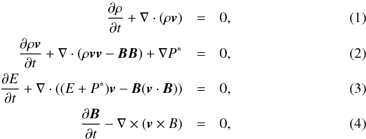 where P∗ = P + B2/ 2 is the total pressure (thermal pressure, P, and magnetic pressure, B2/ 2), and E is the total energy density
 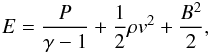 t is the time, ρ = 1.27mHn is the mass density with an assumption of a 10:1 H:He ratio, mH is the mass of a hydrogen atom, n the number density of ions, γ = 5/3 is the adiabatic index for nonrelativistic gas in the non-modification case, v the gas velocity, and B the magnetic field. The temperature of the plasma involved in the simulation is always higher than 104 K. Moreover, a mean atomic mass μ = 0.6 is used for the ionized medium, which means that ρ = μmH(n + ne), where ne is the number density of electrons.
The 3D MHD simulation of the SNR shock front propagating through the turbulent plasma is performed with the PLUTO code (Mignone et al. 2007). In the calculation, the MHD equations are solved with the cell-centered finite-volume scheme with high-order Godunov methods. The magnetic field is evolved with the constrained transport technique to preserve the divergence-free condition, and the fluxes are calculated using the HLL Riemann solver (Miyoshi & Kusano 2005). Moreover, the simulations are performed on a cubic Cartesian domain that extends between − 12 pc to 12 pc for each of the x, y, and z directions. The whole numerical grid has 5123 zones, and a resolution of ~0.05 pc is obtained in each of the directions.
2.2. Simulation setup
Shortly after the supernova explosion with a time t, the ejecta consists of an inner core with a uniform density within a radius rc and an outer part with a density following the power-law distribution (Fraschetti et al. 2010), 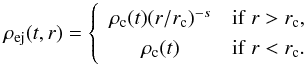 (5)The index s is usually adopt to be 7 for a Type-Ia remnant. Moreover, we assume that the ejecta expands freely to the circumstellar medium, and the velocity for the matter of the ejecta at r is
  (6)With an initial kinetic energy Eej, a mass Mej for the ejecta, and a mass fraction η = 3/7 of the outer part of the ejecta for Type-Ia SNRs (Colgate & Mckee 1969), rc can be calculated with (Jun & Norman 1996)
 ![Mathematical equation: \begin{equation} r_{\rm c} = R_{\rm ej}\left [1-\frac{\eta(3-s)M_{\rm ej}}{4\pi\rho_0R_{\rm ej}^3}\right ]^{1/(3-s)}, \end{equation}](/articles/aa/full_html/2015/07/aa24857-14/aa24857-14-eq41.png) (7)where Rej = 0.8 pc is adopted as the initial radius of the ejecta, and ρ0 is the density of the uniform component of the background medium. The density of the inner core ρc and the velocity at the outer boundary of the ejecta v0 can be obtained with (Jun & Norman 1996; Fang & Zhang 2012)
(7)where Rej = 0.8 pc is adopted as the initial radius of the ejecta, and ρ0 is the density of the uniform component of the background medium. The density of the inner core ρc and the velocity at the outer boundary of the ejecta v0 can be obtained with (Jun & Norman 1996; Fang & Zhang 2012) 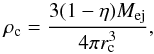 (8)and
 ![Mathematical equation: \begin{equation} v_{0} = E_{\rm ej}^{1/2}\left \{\frac{2\pi \rho_{\rm c}r_{\rm c}^5}{5R_{\rm ej}^2} + \frac{2\pi \rho_{0}R_{\rm ej}^3\left[1-(R_{\rm ej}/r_{\rm c})^{s-5}\right]}{5-s}\right \}^{-1/2}. \end{equation}](/articles/aa/full_html/2015/07/aa24857-14/aa24857-14-eq47.png) (9)To simulate the real environment around SN 1006, the background plasma, in which the shock front propagates, is assumed to be turbulent with a relatively smaller amplitude. In the simulation, the 3D Kolmogorov-like power spectrum, which is consistent with the observations of interstellar turbulence (Armstrong et al. 1995; Chepurnov & Lazarian 2010), is adopted for the turbulent density and magnetic field, i.e., the power spectrum follows
(9)To simulate the real environment around SN 1006, the background plasma, in which the shock front propagates, is assumed to be turbulent with a relatively smaller amplitude. In the simulation, the 3D Kolmogorov-like power spectrum, which is consistent with the observations of interstellar turbulence (Armstrong et al. 1995; Chepurnov & Lazarian 2010), is adopted for the turbulent density and magnetic field, i.e., the power spectrum follows 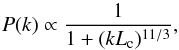 (10)where k is the magnitude of the wavevector, and Lc = 3 pc is the coherence length. The magnetic field consists of a uniform background and a turbulent component; i.e.,
  (11)and the turbulent component can be calculated with (Giacalone & Jokippi 1999)
 ![Mathematical equation: \begin{equation} \delta\vec{B}(x, y, z) = \sum_{n=1}^{N_{\rm m}}A(k_n) \left [ \cos(\alpha_n)\vec{ \hat{x}}_n' + i \sin(\alpha_n) \vec{ \hat{y}}_n' \right ] \exp(ik_n z_n'), \end{equation}](/articles/aa/full_html/2015/07/aa24857-14/aa24857-14-eq52.png) (12)where
(12)where 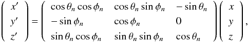 (13)θn and φn represent the direction of propagation of the wave mode n with the wave number kn, polarization αn and phase βn. The amplitude of the wave mode n is (Giacalone & Jokippi 1999)
 ![Mathematical equation: \begin{equation} A^2(k_n)=\sigma_{\rm B}^2\frac{\Delta V_n}{1+(k_n L_c)^{11/3}}\left[ \sum_{n=1}^{N_{\rm m}}\frac{\Delta V_n}{1+(k_n L_c)^{11/3}} \right]^{-1}, \end{equation}](/articles/aa/full_html/2015/07/aa24857-14/aa24857-14-eq59.png) (14)where
(14)where  is the wave variance and the normalization factor
  . In the simulation, Nm = 1000 discrete wave modes are summed with random phases and polarizations to represent the isotropic turbulence. The maximum wavelength of these modes is chosen to be λmax = 15 pc, whereas the minimum wavelength λmin = 0.1 pc, which is twice as large as the grid-cell size in the simulation.
For the fluctuations of the density, a log-normal probability is adopted (Giacalone & Jokippi 2007), i.e., 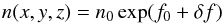 (15)where δf has the 3D Kolmogorov-like power spectrum as δB with a wave variance
  .
.
Based on the detected image in the hard X-rays with Chandra (Cassam-Chenaï et al. 2008), the bump at the NE arc of SN 1006 has an azimuth extension of ~50° (10° ≤ θ ≤ 60°), and each of the three smaller bumps on the SW limb has an extension of ~12°. To reproduce the observed bumps in the NE and SW limbs, one large and three smaller spherical cavities with lower densities are adopted in the background plasma. The temperatures of the plasma in these cavities are determined by assuming that they are in pressure equilibrium with the outer medium. The first cavity with a lower density nc1 is located in the NE part of the simulation domain at (xc1, yc1, zc1) with a radius of Rc1, and the other cavities have a density of nci at (xci, yci, zci) with a radius of Rci (i = 2,3,4).
Parameters for the four lower density cavities.
The supernova explodes at the center of the simulation domain with the explosion energy Eej = 1.5 × 1051 erg, the mass of the ejecta Mej = 1.4 M⊙. The background plasma has a temperature of TISM = 104 K, a turbulent density with n0 = 0.035 cm-3, f0 = 0, δf = 0.41, and a turbulent magnetic field with B0 = 3μG, Bx = 0, By = −B0cos(π/ 4), Bz = B0sin(π/ 4), σB=0.1. Moreover, the centers of the four spherical cavities are located at the plane xc = 0 pc, and the other parameters are shown in Table 1.
2.3. Synchrotron emission
The relativistic electrons accelerated by the forward shock in SNRs can emit photons with energies from radio to X-rays through synchrotron radiation. Assuming these electrons have a power law distribution with a cutoff around the maximum energy Emax, i.e., 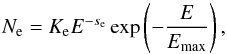 (16)where se is the index, the emissivity of the synchrotron radiation for the electrons can be approximated by (Katsuda et al. 2010)
 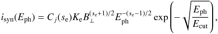 (17)where Ke is a factor describing the amount of the relativistic electrons, Cj is a constant, B⊥ is the magnetic field perpendicular to the line of sight, Eph is the energy of the photon, and
  is the exponential cutoff energy of the synchrotron radiation. The above assumption on the energy distribution of the electrons does not include any post-shock evolution of these relativistic particles. Moreover, we ignore the variation in the Ecut along the remnant outline, which have been indicated by the X-ray observations (Rothenflug et al. 2004; Miceli et al. 2014). Non-thermal X-rays from a SNR are usually characterized by a cutoff frequency that corresponds to the maximum energy of the electrons accelerated by the SNR shock. Based on the theory of the diffusive shock acceleration, Emax is determined by the shock speed, age, and various energy loss mechanisms (Reynolds 1998). The effect of the maximum energy, which varies both with time and with the surface of the remnant, on the synchrotron spectrum must be taken into account to accurately synthesize the X-ray emission from the SNR (Orlando et al. 2011).
The studies from the hybrid simulations by Caprioli & Spitkovsky (2014a) show that the acceleration efficiency of ions at nonrelativistic shocks depend heavily on the angle between the shock normal and the direction of the preshock magnetic field. The acceleration of the ions is efficient for parallel and quasi-parallel shocks (Caprioli & Spitkovsky 2014a). Assuming thalethe electrons share the same feature as the ions, the acceleration of the electrons follow the quasi-parallel model. The normalization of the relativistic electrons is multiplied by a factor of cos2θBn, where θBn is the angle between the preshock magnetic field and the shock normal. In our simulations, the amplitude of the turbulent component of the ambient magnetic field is relatively small, therefore calculating θBn does not take the turbulent component of the magnetic field into account.
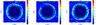 |
Fig. 1 Spatial distribution of the density (ρ) from the 3D simulation with an age of 1000 yr in the plane z = 0 (left panel), x = 0 (middle panel), and y = 0 (right panel). The mass density is in units of 1.67 × 10⁻²⁴ g cm-3. |
For the spherical shock of a SNR, the accelerated particles can escape from the acceleration process beyond the contact discontinuity since the magnetic field strength is negligible within the discontinuity; moreover, the relativistic electrons suffer serious energy loss due to the synchrotron radiation behind the shock. As a result, the high-energy electrons distributed closely to the SNR shock. According to the thermal injection theory on the diffusive acceleration regime, more charged particles can be injected into the acceleration with a higher density of the plasma immediately downstream of the shock (e.g., Blasi et al. 2005). It is difficult to accurately determine the number density of the accelerated particles at a location downstream of the shock because it depends on the density distribution of the background medium swept by the shock and the detail transportation of these relativistic particles, especially for the shock disturbed by inhomogeneous medium with a complex periphery. In this paper, the relativistic electrons are supposed to distribute in the thin area along the forward shock, and we simply assume that Ke in the SNR is proportional to the local density n at a certain age of the remnant since generally more charged particles can be injected in the acceleration process with a higher density at the shock. Therefore, when taking this effect and the quasi-parallel acceleration into account, Ke ∝ ncos2θBn is adopted in the simulation. The cutoff energy of the detected non-thermal X-rays from SN 1006 varies azimuthly along the non-thermal limb, and a mean value of ~0.2 keV is derived based on the observations with Chandra (Allen et al. 2008) and XMM-Newton (Rothenflug et al. 2004; Miceli et al. 2014). We simply assume the cutoff energy Ecut = 0.2 keV for all directions although the measured cut-off energy varies both radially and along the remnant outline (Rothenflug et al. 2004; Allen et al. 2008; Miceli et al. 2014).
Magnetic field can be greatly amplified at SNR shocks caused by the acceleration of charged particles. The hybrid simulations also indicated that the amplification of the magnetic field correlates with the efficiency of the ion acceleration. Caprioli & Spitkovsky (2014b) found that the upstream magnetic field for non-relativistic shocks could be significantly amplified, and the strength of the amplified magnetic field generated via the resonant streaming instability have the relation (Lagage & Cesarsky 1983; Amato & Blasi 2006; Caprioli & Spitkovsky 2014b), 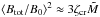 , where
  is the Mach number of the upstream medium in the shock reference frame, ζcr is the normalized pressure in the accelerated particles, and ζcr is related to the acceleration efficiency of the non-thermal particles. The generation of the magnetic field turbulence cannot be consistently tackled by the MHD simulations, which ignore the acceleration of the charged particles, and we simply assume that the strength of amplified magnetic field is proportional to the square root of the local number density of the accelerated particles in calculating the emissivity of the synchrotron radiation, i.e.,
  .
.
3. Simulation results
Figure 1 shows the spatial distribution of the density in the simulation domain after a time of 1000 yr. The slices in the plane z = 0, x = 0, and y = 0 are shown in the left, middle, and right panels, respectively. In the beginning of the simulation, the density and the pressure of the ejecta are high enough to drive a strong shock in the turbulent background. The ambient plasma is continually heated and compressed by the shock. Moreover, a reverse shock is produced since the shocked circumstellar medium pushes back on the ejecta (Truelove & McKee 1999). The inner ejecta expands freely until it is swept by the reverse shock, and both the density and the pressure of the unshocked ejecta decrease quickly during the expansion. The forward and the reverse shocks are separated by the contact discontinuity, where the Rayleigh-Taylor instability is triggered. Figure 2 indicates the distribution of the averaged density on the radial distance to the center of the explosion.
The forward shock is located at a radius of ~9.5 pc, which is consistent with the detected extension of the remnant for a distance of ~2.18 kpc (Winkler et al. 2003). As a consequence of the turbulent background, the shape of the forward shock is slightly distorted. In the forward shock, the inhomogeneous distribution of the density is obtained because the materials swept by the shock in various directions are different from each other. In some places, knots and filaments are produced since more material has been swept by the shock than in the other locations. In the middle panel of Fig. 1, the distribution of the density shows one bump in the NE rim of the remnant and three smaller ones in the SW limb because the shock speed is not very decelerated as the shock sweeps the lower density cavities. The radius of the forward shock from the simulation is indicated in Fig. 3 as a function of the azimuth angle (θ). In the ranges 10°<θ< 50° and 220°<θ< 270°, the radius significantly exceeds the averaged one owing to the existence of the cavities, and the other dispersion is the result of the turbulent property of the ambient medium. The resulting azimuth extensions of the bumps on the limbs are consistent with the detected ones due to the NE breakout with an extension of ~50° and with the three ones in the SW limb with an averaged extension of ~12°.
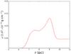 |
Fig. 2 Density profile as a function of the radial distance to the center of the remnant. |
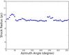 |
Fig. 3 Shock radius as a function of the azimuth angle when the LOS is aligned with the x axis. |
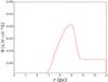 |
Fig. 4 Strength of the magnetic field as a function of the radial distance to the center of the remnant. |
 |
Fig. 5 Spatial distribution of the pressure in units of 1.67 × 10⁻⁸ dyn cm-2 from the 3D simulation with an age of 1000 yr. The left, middle, and right panels are for the plane z = 0, x = 0, and y = 0, respectively. |
The magnetic filed strength in the remnant as a function of the radial distance is shown in Fig. 4. The magnetic field is amplified at the location of the contact discontinuity due to the Rayleigh-Taylor instability. Moreover, the magnetic field both in the shocked ejecta within the contact discontinuity and in the interior of the remnant becomes negligible because of the expansion of the ejecta, and the similar feature can also be seen in Fig. 5 for the spatial distribution of the pressure.
 |
Fig. 6 Synthesis morphologies of the non-thermal synchrotron radiation with energies from 2−4.5 keV when the LoS is aligned with the z (left panel), x (middle panel), and y (right panel) axis. The intensity is in arbitrary units. |
The distribution of the electrons accelerated by the forward shock is assumed to follow the quasi-parallel scenario, i.e., Ne ∝ ncos2θBn. Because the energetic electrons can escape from the shock owing to weak confinement of the magnetic field and because these electrons suffer strong energy loss due to the synchrotron radiation, we suppose that the electrons emitting the high-energy synchrotron emission are distributed close to the shock front; i.e., the energetic electrons are distributed in the locations with pressure p> 10-8 dyn cm-2. Furthermore, assuming that the strength of the amplified magnetic field is proportional to the number density of the accelerated electrons, we show the resulting synchrotron morphologies of the hard X-rays with energies from 2−4.5 keV in the amplified magnetic field when the line of sight (LoS) is aligned with the z, x, and y axes in the left, middle, and right panels in Fig. 6, respectively. The image with the LoS along the x direction shows a bilateral shape due to the quasi-parallel scenario of the acceleration process, in which the efficiency of the acceleration is high at locations with the shock normal parallel or antiparallel to the background magnetic field. However, the non-thermal X-rays in the NW and SE parts of the remnant are faint because of the inefficient particle acceleration. Although the morphology shows a general circular shape, some disturbances still exist owing to the turbulent feature of the background plasma. Besides the NE and SW bumps, the morphologies of the remnant both in radio and in X-rays have the knotty and filamentary structures, and it deviates from the circular shape since the SNR forward shock is transported into the turbulent medium.
The images in the non-thermal X-rays detected with XMM-Newton (Rothenflug et al. 2004; Miceli et al. 2012) and Chandra (e.g., Long et al. 2003; Cassam-Chenaï et al. 2008; Winkler et al. 2014) have distinct bumps along the SNR shell. The image when the LoS is aligned with the x direction show a two-arc structure, which is consistent with the observed morphology in the energy band 2−4.5 keV by Chandra and XMM-Newton. The largest bump located at the NE arc of the remnant can be reproduced in the simulation by imposing a spherical region with a density of 0.4n0 and a radius of 2.5 pc. On the opposite limb, the smaller bumps can be explained with the three spherical cavities with a density of 0.2n0 swept by the shock front. The radial profiles of the intensities for the azimuth range 0°<θ< 90° and 180°<θ< 270° of the synchrotron radiation are shown in Figs. 7 and 8, respectively. The intensity peaks at a radius of around 9 pc, and the other peaks beyond this distance result from the lower density cavities.
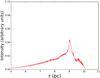 |
Fig. 7 Radial profile for the intensity of the synchrotron radiation with the azimuth range 0°<θ< 90° when the LoS is aligned with the x axis. The intensity is in arbitrary unit. |
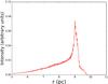 |
Fig. 8 Radial profile for the intensity of the synchrotron radiation with the azimuth range 180°<θ< 270°. The others are the same as in Fig. 7. |
The radius of the cavity determines the azimuth extension of the bump on the limb of SN 1006, and the distance of the bump edge to the center of the remnant depends heavily on the density of the cavity. The simulation in this paper shows that the radius of the NE cavity is about 2.5 pc. The resulting morphologies of the remnant for nc1 = 0.2n0 and 0.8n0 are shown in Figs. 9 and 10, respectively. Moreover, Fig. 11 indicates the azimuth distribution of the radius for the NE limb of the remnant with nc1 = 0.2n0, 0.4n0, and 0.8n0. The morphology with nc1 = 0.4n0 is more like the hard X-ray images detected with Chandra or XMM-Newton than like nc1 = 0.2n0 and 0.8n0.
The expansion rates of the NW limb of SN 1006 based on the Chandra observations have been proposed by Katsuda et al. (2009). For the NE limb, the proper motion has an averaged value of ~ yr-1, which is consistent with that derived from the radio observations for the entire remnant with a value of ~
 yr-1 (Moffett et al. 1993). The derived shock velocities for the NE limb based on the Chandra observations range from 4000 to 6000 km s-1 as a function of the azimuth angle for a distance of 2.2 kpc. Recently, Winkler et al. (2014) have given the measurement of the X-ray proper motion for the entire periphery of SN 1006. The derived expansion velocity in the NW limb is consistent with Katsuda et al. (2009), and the results show that the velocity varied significantly with azimuth along the entire rim of the remnant. Especially, the highest velocity, which is about 1.5 times the averaged one along the NE periphery, was found to be located at the SE limb. The velocities of the forward shock distributed over the azimuth angle from the simulation are illustrated in Fig. 12. Along the NE periphery with the azimuth range 0°<θ< 90°, the forward shock expands with velocities around 5000 km s-1 with dispersions due to the existence of the cavity and the turbulent medium, and the variation in the velocity over the azimuth angle is generally consistent with the results derived from the Chandra observations (Katsuda et al. 2009; Winkler et al. 2014). For the SW limb, the measured velocities in Winkler et al. (2014) for the expansion of the outer most X-rays vary significantly in the range from ~4000 to ~8000 km s-1 with the azimuth angle 180°<θ< 270°. In the range of 200°<θ< 240°, the variation tendency obtained from the simulation is generally consistent with the observation, although the exact values have some differences. Moreover, a value of >7000 km s-1 is derived for the shock velocity along the SE periphery and at some places on the SW limb, and these expansion rates can be explained as X-rays emitted from the ejecta overtaking the forward shock. For the NW periphery, the observations show that the expansion velocities are almost <4000 km s-1, which results from a denser medium located in the NW region around the remnant. However, because the NW limb is not luminous in non-thermal X-rays/radio, we do not take the denser medium into account in this paper.
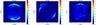 |
Fig. 9 Synthesis morphologies of the non-thermal synchrotron radiation for nc1 = 0.2n0. Others are the same as in Fig. 6. |
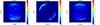 |
Fig. 10 Synthesis morphologies of the non-thermal synchrotron radiation for nc1 = 0.8n0. Others are the same as in Fig. 6. |
Figure 13 shows the simulated morphology for the remnant evolved in a uniform ambient medium. The bilateral shape with luminous NE and SW limbs is also held with the quasi-parallel scenario for the acceleration process when the LoS is aligned with the x axis. With the uniform background plasma, the distribution of the intensity that changes regularly and smoothly along the NE/SW limb is inconsistent with the observed ones that have the knotty and filamentary structures and deviations from the circular shape in the radio and X-rays.
A SNR shock can be modified due to the acceleration of the cosmic rays, and the distance between the contact discontinuity and the forward shock is significantly decreased in the case of efficient acceleration (Blondin & Ellison 2001; Wang 2011; Warren & Blondin 2013). As a result, a fraction of the ejecta can approach closer or even overtake the forward shock, and the remnant outline is disturbed by the hydrodynamic instabilities. We also investigate the influence of the shock modification on the resulting morphology of the remnant by using an artificially lower adiabatic index as in Warren & Blondin (2013). Figure 14 illustrates the resulting distribution of density of the remnant evolved in a uniform medium with an adiabatic index of 1.2, which is also adopted in Warren & Blondin (2013) to study the effect of the cosmic ray acceleration on the morphology of the forward shock. The higher compressibility increases the density downstream of the forward shock compared with γ = 5/3, and the Rayleigh-Taylor fingers can extend more closely to the forward shock to influence the edge of the shock as the remnant evolved in the medium. Assuming the accelerated electrons are distributed close to the forward shock in the regions with the pressure above 0.45, the resulting morphologies of the synchrotron emission along the z, x, and y directions are shown in the left, middle, and right panels in Fig. 15, respectively. Along the z and y directions, bubbles are visible in the morphologies since the hydrodynamical instabilities overtake the forward shock. Although some of the fingers can extend beyond the shock boundary to produce bubbles visible on the forward shock as in Warren & Blondin (2013), the extensions of these bubbles are usually not as large as the bump on the NW limb of SN 1006. The big bump at the NE rim of SN 1006 cannot therefore be explained as these bubbles. However, the small bumps on the SW limb can also be interpreted as the bubbles when the Rayleigh-Taylor fingers effectively overtake the forward shock in the case of the efficient particle acceleration at the forward shock.
4. Summary and discussion
Based on the observations in the non-thermal X-ray and radio bands, the SNR SN 1006 indicates a generally bilateral shape with two opposite bright limbs. This feature suggests that the circumstellar medium around the remnant is more uniform than the other SNRs with complex shapes, such as RX J0852.0-4622 and RX J1713.7-3946. However, some inhomogeneities still exist along the shell of SN 1006, especially the distinct bumps that are obvious in both the radio and the X-ray morphologies. Besides the bumps, the inhomogeneities cannot be explained by isotropic supernova ejecta evolved in a uniform medium, in which the circular shape of the remnant is not disturbed and the knotty and filamentary morphology cannot be reproduced.
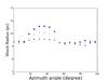 |
Fig. 11 Shock radius as a function of the azimuth angle in the range 0°<θ< 100° for nc1 = 0.2n0 (square), 0.4n0 (dot), and 0.8n0 (triangle). |
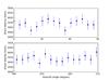 |
Fig. 12 Velocity of the forward shock as a function of the azimuth angle for the range 0°<θ< 90° (upper panel) and 180°<θ< 270° (lower panel). |
To give a more realistic explanation to the detected hard X-ray/radio morphology of SN 1006, we assumed that the ambient medium is turbulent with a relatively small amplitude to ensure that the uniformity, which is derived from the bilateral shape of the remnant, of the background plasma is not significantly disturbed. The observed deviation of the circular shape of the hard X-ray morphologies with knotty and filamentary structure can be explained as the SNR evolved in the turbulent medium, although we did not fit the exact deviations from the observations by exploring the parameter space on the turbulent background plasma. Furthermore, several spherical cavities with lower densities were adopted in the background plasma to reproduce the distinct bumps in the detected morphologies of the synchrotron emission.
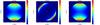 |
Fig. 13 Synthesis morphologies of the non-thermal synchrotron radiation with energies from 2−4.5 keV when the LoS is aligned with the z (left panel), x (middle panel), and y (right panel) axes in the scenario of the remnant evolved in a uniform medium. The intensity is in arbitrary units. |
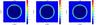 |
Fig. 14 Spatial distribution of the density (ρ) from the 3D simulation with an age of 1000 yr for γ = 1.2. The others are the same as Fig. 1. |
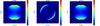 |
Fig. 15 Synthesis morphologies of the non-thermal synchrotron radiation with energies from 2−4.5 keV when the LoS is aligned with the z (left panel), x (middle panel), and y (right panel) axis in the scenario of the remnant evolved in a uniform medium with γ = 1.2. The intensity is in arbitrary units. |
In this paper, the knotty and filamentary structure of the remnant was generated as the forward shock wave expanding into the inhomogeneous medium. Some other mechanisms that can lead to the structure have been proposed. For example, Orlando et al. (2012) investigated the influence of the ejecta clumping on the density distribution of the post-shock region for a Type-Ia SNR. They find that the reduction of the distance between the forward shock and the contact discontinuity is also produced (even more efficiently) by the ejecta fragmentation (Orlando et al. 2012). Moreover, the growth of the RT instabilities is greatly enhanced by the interactions among the clumps, and the enhanced instabilities send the ejecta closer to or even beyond the forward shock. Then the outline of the remnant is disturbed, and a knot and filamentary structure are produced.
The ejecta clumping can lead to the occurrence of several protrusions due to the clumps overtaking the forward shock, and the model in Orlando et al. (2012) successfully explained the occurrence of protrusions in some SNRs, such as SN 1006 (e.g., Rakowski et al. 2011) and Tycho’s SNR (Hwang & Gotthelf 1997; Velazquez et al. 1998). However, the bump on the NE limb in the morphology of SN 1006 has a relatively large scale, and it seems that they should not be produced by the RT instability fingers overtaking the forward shock. In this paper, the big bump at the NE rim of the remnant is formed by the cavity in the background medium. The smaller bumps like those on the SW limb of SN 1006 can be explained either by cavities swept by the forward shock or by the bubbles resulting from the Rayleigh-Taylor fingers that overtake the forward shock in the scenario of efficient cosmic ray acceleration. The physical origin of these cavities is not clear.
The recent hybrid simulation shows that underdense cavities, which have scales comparable to the gyroradius of the highest-energy particles in the simulation, can be produced in the shock precursor of the quasi-parallel shocks with efficient particle acceleration due to the streaming instability (Caprioli & Spitkovsky 2014a). The turbulent medium with those cavities around the remnant imposed in our simulation can be considered as an approximation of lots of the cavities upstream of the quasi-parallel shock due to the particle acceleration. Moreover, lower density cavities around a Type-Ia remnant can also be generated as blowing of the wind from the progenitor system (e.g., Kashi & Soker 2011; Shen et al. 2012; Broersen et al. 2014).
The hydrodynamic instabilities growing at the contact discontinuity are related to the numerical resolution, and the plasma properties in the mixing region between the contact discontinuity and the forward shock are influenced by these instabilities (Blondin & Ellison 2001). To increase the precision of the resolution in a 3D simulation is very expensive, so we adopted 5123 zones to simulate the evolution of the remnant in the medium with a resolution of ~0.05 pc obtained in the simulations. In the non-modification scenario with γ = 5/3, the instabilities cannot extend very close to the forward shock, and the resulting morphology of emission is less influenced. Moreover, even in the modification case, the bubbles on the surface of the remnant stemming from the instabilities overtaking the forward shock are unlikely to have enough extensions to explain the big bump located on the NW limb of SN 1006. Therefore, our results are not influenced by the resolution adopted in this paper.
The two assumptions on the acceleration of charged particles at SNR shocks and the amplification of the magnetic field were adopted to obtain the distribution of the energetic electrons in the SNR shell. The acceleration and the amplification cannot be self-consistently tackled with MHD simulations that ignore the acceleration process of charged particles by the shock. Both the recent hybrid simulations and the radio observations on SN 1006 support the quasi-parallel scenario for the acceleration at SNR shocks. Therefore, the quasi-parallel scenario was adopted, and two more assumptions on the strength of the amplified magnetic field and the spatial distribution of the energetic electrons producing the non-thermal X-rays were used to achieve the morphology of the synchrotron emission at any given energy.
We paid attention to the bumps at the NE/SW limb, which is bright in non-thermal X-rays, by simulating the remnant as an explosion evolved in a turbulent medium with either spherical cavities with the lower densities or modifications of the morphologies of the remnant due to the efficient cosmic ray acceleration. In the NW part of the remnant, a denser medium interacting with the shell exists based on the bright filament in soft X-rays (Dubner et al. 2002; Acero et al. 2007; Nikolić et al. 2013), and Scheiter et al. (2010) has investigated the influence of the NE cloud on the dynamical properties of the remnant by 2D MHD simulations. However, the NW region is not luminous in the non-thermal X-rays, and the dense cloud around the NW limb is not taken into account in this paper.
Acknowledgments
We acknowledge the referee for the valuable comments that helped improve this paper. This work is partially supported by the National Natural Science Foundation of China (NSFC 11433004, 11173020), by the Key Project of Chinese Ministry of Education (212160), by the Doctoral Fund of Ministry of Education of China (RFDP 20115301110005), by the West Light Foundation of the Chinese Academy of Sciences (W8090303), by the Open Research Program of the Key Laboratory for the Structure and Evolution of Celestial Objects, Chinese Academy of Sciences (OP201402), and by the Top Talents Program of Yunnan Province, China.
References
- Acero, F., Ballet, J., & Decourchelle, A. 2007, A&A, 475, 883 [NASA ADS] [CrossRef] [EDP Sciences] [Google Scholar]
- Acero, F., Aharonian, F., Akhperjanian, A. G., et al. (HESS Collaboration) 2010, A&A, 516, A62 [NASA ADS] [CrossRef] [EDP Sciences] [Google Scholar]
- Allen, G. E., Houck, J. C., & Sturner, S. J. 2008, ApJ, 683, 773 [NASA ADS] [CrossRef] [Google Scholar]
- Amato, E., & Blasi, P. 2006, MNRAS, 371, 1251 [NASA ADS] [CrossRef] [Google Scholar]
- Armstrong, J. W., Rickett, B. J., & Spangler, S. R. 1995, ApJ, 443, 209 [NASA ADS] [CrossRef] [Google Scholar]
- Bamba, A., Yamazaki, R., Keno, M., & Koyama, K. 2003, ApJ, 589, 827 [NASA ADS] [CrossRef] [Google Scholar]
- Blasi, P., Gabici, S., & Vannoni, G. 2005, MNRAS, 361, 907 [NASA ADS] [CrossRef] [Google Scholar]
- Blondin, J. M., & Ellison, D. C. 2001, ApJ, 560, 244 [NASA ADS] [CrossRef] [Google Scholar]
- Bocchino, F., Orlando, S., Miceli, M., & Petruk, O. 2011, A&A, 531, A129 [NASA ADS] [CrossRef] [EDP Sciences] [Google Scholar]
- Broersen, S., Chiotellis, A., Vink, J., & Bamba, A. 2014, MNRAS, 441, 3040 [NASA ADS] [CrossRef] [Google Scholar]
- Caprioli, D., & Spitkovsky, A. 2014a, ApJ, 783, 91 [NASA ADS] [CrossRef] [Google Scholar]
- Caprioli, D., & Spitkovsky, A. 2014b, ApJ, 794, 46 [Google Scholar]
- Cassam-Chenaï, G., Hughes, J. P., Reynoso, E. M., Badenes, C., & Moffett, D. 2008, ApJ, 680, 1180 [NASA ADS] [CrossRef] [Google Scholar]
- Chepurnov, A., & Lazarian, A. 2010, ApJ, 710, 853 [NASA ADS] [CrossRef] [Google Scholar]
- Colgate, S. A., & McKee, C. 1969, ApJ, 157, 623 [NASA ADS] [CrossRef] [Google Scholar]
- Drury, L. O’C. 2001, Rep. Prog. Phys., 46, 973 [Google Scholar]
- Dubner, G. M., Giacani, E. B., Goss, W. M., Green, A. J., & Nyman, L. Å. 2002, A&A, 387, 1047 [NASA ADS] [CrossRef] [EDP Sciences] [Google Scholar]
- Fang, J., & Zhang, L. 2012, MNRAS, 424, 2811 [NASA ADS] [CrossRef] [Google Scholar]
- Fang, J., Yu, H., & Zhang, L. 2014, MNRAS, 445, 2484 [NASA ADS] [CrossRef] [Google Scholar]
- Fraschetti, F., Teyssier, R., Ballet, J., & Decourchelle, A. 2010, A&A, 515, A104 [NASA ADS] [CrossRef] [EDP Sciences] [Google Scholar]
- Giacalone, J., & Jokipii, J. R. 1999, ApJ, 520, 240 [Google Scholar]
- Giacalone, J., & Jokipii, J. R. 2007, ApJ, 663, L41 [NASA ADS] [CrossRef] [Google Scholar]
- Guo, F., Li, S., Li, H., Giacalone, J., Jokipii, J. R., & Li, D. 2012, ApJ, 747, 98 [NASA ADS] [CrossRef] [Google Scholar]
- Hnatyk, B., & Petruk, O. 1999, A&A, 344, 295 [NASA ADS] [Google Scholar]
- Hwang, U., & Gotthelf, E. V. 1997, ApJ, 475, 665 [NASA ADS] [CrossRef] [Google Scholar]
- Jun, B.-I., & Norman, M. L. 1996, ApJ, 465, 800 [NASA ADS] [CrossRef] [Google Scholar]
- Kashi, A., & Soker, N. 2011, MNRAS, 417, 1466 [NASA ADS] [CrossRef] [Google Scholar]
- Katsuda, S., Petre, R., Long, K. S., et al. 2009, ApJ, 692, L105 [NASA ADS] [CrossRef] [Google Scholar]
- Katsuda, S., Peter, R., Mori, K., et al. 2010, ApJ, 723, 383 [NASA ADS] [CrossRef] [Google Scholar]
- Koyama, K., Petre, R., Gotthelf, E. V., et al. 1995, Nature, 378, 255 [NASA ADS] [CrossRef] [Google Scholar]
- Lagage, P. O., & Cesarsky, C. J. 1983, A&A, 118, 223 [NASA ADS] [Google Scholar]
- Long, K. S., Reynolds, S. P., & Raymond, J. C., et al. 2003, ApJ, 586, 1162 [NASA ADS] [CrossRef] [Google Scholar]
- Malkov, M. A., & Drury, L. O’C. 2001, Rep. Prog. Phys., 64, 429 [NASA ADS] [CrossRef] [Google Scholar]
- Miceli, M., Bocchino, F., Iakubovskyi, D., et al. 2009, A&A, 501, 239 [NASA ADS] [CrossRef] [EDP Sciences] [Google Scholar]
- Miceli, M., Bocchino, F., Decourchelle, A., et al. 2012, A&A, 546, A66 [NASA ADS] [CrossRef] [EDP Sciences] [Google Scholar]
- Miceli, M., Acero, F., Dubner, G., et al. 2014, ApJ, 782, L33 [NASA ADS] [CrossRef] [Google Scholar]
- Mignone, A., Bodo, G., Massaglia, S., et al. 2007, ApJS, 170, 228 [Google Scholar]
- Miyoshi, T., & Kusano, K. 2005, J. Comput. Phys., 315, 344 [Google Scholar]
- Moffett, D. A., Goss, W. M., & Reynolds, S. P. 1993, AJ, 106, 1566 [NASA ADS] [CrossRef] [Google Scholar]
- Nikolić, S., van de Ven, G., Heng, K., et al. 2013, Science, 340, 45 [NASA ADS] [CrossRef] [Google Scholar]
- Orlando, S., Bocchino, F., Reale, F., Peres, G., & Petruk, O. 2007, A&A, 470, 927 [NASA ADS] [CrossRef] [EDP Sciences] [Google Scholar]
- Orlando, S., Petruk, O., Bocchino, F., & Miceli, M. 2011, A&A, 526, A129 [NASA ADS] [CrossRef] [EDP Sciences] [Google Scholar]
- Orlando, S., Bocchino, F., Miceli, M., Petruk, O., & Pumo, M. L. 2012, ApJ, 749, 156 [NASA ADS] [CrossRef] [Google Scholar]
- Rakowski, C. E., Laming, J. M., Hwang, U., et al. 2011, ApJ, 735, L21 [NASA ADS] [CrossRef] [Google Scholar]
- Raymond, J. C., Korreck, K. E., Sedlacek, Q. C., et al. 2007, ApJ, 659, 1257 [NASA ADS] [CrossRef] [Google Scholar]
- Reynolds, S. P. 1998, ApJ, 493, 375 [NASA ADS] [CrossRef] [Google Scholar]
- Reynoso, E. M., Hughes, J. P., & Moffett, D. A. 2013, AJ, 145, 104 [NASA ADS] [CrossRef] [Google Scholar]
- Rothenflug, R., Ballet, J., Dubner, G., et al. 2004, A&A, 425, 121 [NASA ADS] [CrossRef] [EDP Sciences] [Google Scholar]
- Schneiter, E. M., Velázquez, P. F., Reynoso, E. M., & de Colle, F. 2010, MNRAS, 408, 430 [NASA ADS] [CrossRef] [Google Scholar]
- Shen, K. J., Bildsten, L., Kasen, D., & Quataert, E. 2012, ApJ, 748, 35 [NASA ADS] [CrossRef] [Google Scholar]
- Truelove, J. K., & McKee, C. F. 1999, ApJS, 120, 299 [NASA ADS] [CrossRef] [Google Scholar]
- Velazquez, P. F., Gomez, D. O., Dubner, G. M., de Castro, G. G., & Costa, A. 1998, A&A, 334, 1060 [NASA ADS] [Google Scholar]
- Wang, C. Y. 2011, MNRAS, 415, 83 [NASA ADS] [CrossRef] [Google Scholar]
- Wang, B., & Han, Z. 2012, New Astron. Rev., 56, 122 [NASA ADS] [CrossRef] [Google Scholar]
- Warren, D. C., & Blondin, J. M. 2013, MNRAS, 429, 3099 [NASA ADS] [CrossRef] [Google Scholar]
- Winkler, P. F., Gupta, G., & Long, K. S. 2003, ApJ, 585, 324 [NASA ADS] [CrossRef] [Google Scholar]
- Winkler, P. F., Williams, B. J., Reynolds, S. P., et al. 2014, ApJ, 781, 65 [NASA ADS] [CrossRef] [Google Scholar]
- Yang, C., Liu, S., Fang, J., & Li, H. 2015, A&A, 573, A37 [NASA ADS] [CrossRef] [EDP Sciences] [Google Scholar]
All Tables
All Figures
|
Fig. 1 Spatial distribution of the density (ρ) from the 3D simulation with an age of 1000 yr in the plane z = 0 (left panel), x = 0 (middle panel), and y = 0 (right panel). The mass density is in units of 1.67 × 10⁻²⁴ g cm-3. |
| In the text | |
|
Fig. 2 Density profile as a function of the radial distance to the center of the remnant. |
| In the text | |
|
Fig. 3 Shock radius as a function of the azimuth angle when the LOS is aligned with the x axis. |
| In the text | |
|
Fig. 4 Strength of the magnetic field as a function of the radial distance to the center of the remnant. |
| In the text | |
|
Fig. 5 Spatial distribution of the pressure in units of 1.67 × 10⁻⁸ dyn cm-2 from the 3D simulation with an age of 1000 yr. The left, middle, and right panels are for the plane z = 0, x = 0, and y = 0, respectively. |
| In the text | |
|
Fig. 6 Synthesis morphologies of the non-thermal synchrotron radiation with energies from 2−4.5 keV when the LoS is aligned with the z (left panel), x (middle panel), and y (right panel) axis. The intensity is in arbitrary units. |
| In the text | |
|
Fig. 7 Radial profile for the intensity of the synchrotron radiation with the azimuth range 0°<θ< 90° when the LoS is aligned with the x axis. The intensity is in arbitrary unit. |
| In the text | |
|
Fig. 8 Radial profile for the intensity of the synchrotron radiation with the azimuth range 180°<θ< 270°. The others are the same as in Fig. 7. |
| In the text | |
|
Fig. 9 Synthesis morphologies of the non-thermal synchrotron radiation for nc1 = 0.2n0. Others are the same as in Fig. 6. |
| In the text | |
|
Fig. 10 Synthesis morphologies of the non-thermal synchrotron radiation for nc1 = 0.8n0. Others are the same as in Fig. 6. |
| In the text | |
|
Fig. 11 Shock radius as a function of the azimuth angle in the range 0°<θ< 100° for nc1 = 0.2n0 (square), 0.4n0 (dot), and 0.8n0 (triangle). |
| In the text | |
|
Fig. 12 Velocity of the forward shock as a function of the azimuth angle for the range 0°<θ< 90° (upper panel) and 180°<θ< 270° (lower panel). |
| In the text | |
|
Fig. 13 Synthesis morphologies of the non-thermal synchrotron radiation with energies from 2−4.5 keV when the LoS is aligned with the z (left panel), x (middle panel), and y (right panel) axes in the scenario of the remnant evolved in a uniform medium. The intensity is in arbitrary units. |
| In the text | |
|
Fig. 14 Spatial distribution of the density (ρ) from the 3D simulation with an age of 1000 yr for γ = 1.2. The others are the same as Fig. 1. |
| In the text | |
|
Fig. 15 Synthesis morphologies of the non-thermal synchrotron radiation with energies from 2−4.5 keV when the LoS is aligned with the z (left panel), x (middle panel), and y (right panel) axis in the scenario of the remnant evolved in a uniform medium with γ = 1.2. The intensity is in arbitrary units. |
| In the text | |
Current usage metrics show cumulative count of Article Views (full-text article views including HTML views, PDF and ePub downloads, according to the available data) and Abstracts Views on Vision4Press platform.
Data correspond to usage on the plateform after 2015. The current usage metrics is available 48-96 hours after online publication and is updated daily on week days.
Initial download of the metrics may take a while.