| Issue |
A&A
Volume 554, June 2013
|
|
|---|---|---|
| Article Number | A115 | |
| Number of page(s) | 9 | |
| Section | The Sun | |
| DOI | https://doi.org/10.1051/0004-6361/201220933 | |
| Published online | 13 June 2013 | |
First evidence of interaction between longitudinal and transverse waves in solar magnetic elements
1 Max Planck Institute for Solar System Research, Max-Planck-Str. 2, 37191 Katlenburg-Lindau, Germany
e-mail: This email address is being protected from spambots. You need JavaScript enabled to view it.
2 School of Space Research, Kyung Hee University, Yongin, 446-701 Gyeonggi, Republic of Korea
3 IAC Instituto de Astrofísica de Canarias, Vía Láctea s/n, 38205 La Laguna, Tenerife, Spain
4 Departamento de Astrofísica, Universidad de La Laguna, 38205 La Laguna, Tenerife, Spain
Received: 17 December 2012
Accepted: 24 April 2013
Abstract
Small-scale magnetic fields are thought to play an important role in the heating of the outer solar atmosphere. By taking advantage of the unprecedented high-spatial and temporal cadence of the Imaging Magnetograph eXperiment (IMaX), the filter vector polarimeter on board the Sunrise balloon-borne observatory, we study the transversal and longitudinal velocity oscillations in small magnetic elements. The results of this analysis are then compared to magnetohydrodynamic (MHD) simulations, showing excellent agreement. We found buffeting-induced transverse oscillations with velocity amplitudes of the order of 1–2 km s-1 to be common along with longitudinal oscillations with amplitudes ~0.4 km s-1. Moreover, we also found an interaction between transverse oscillations and longitudinal velocity oscillations, showing a ± 90° phase lag at the frequency at which they exhibit the maximum coherence in the power spectrum. Our results are consistent with the theoretical picture in which MHD longitudinal waves are excited inside small magnetic elements as a response of the flux tube to the forcing action of the granular flows.
Key words: Sun: photosphere / Sun: oscillations / Sun: helioseismology
© ESO, 2013
1. Introduction
Magnetic fields play a major role in the dynamics and the energetics of the solar atmosphere. They are present over a wide range of spatial scales (Solanki et al. 2006), from very small elements (Lagg et al. 2010) at or below the best current spatial resolution achieved by modern solar telescopes (≃100 km), up to large sunspots with diameters of the order of 70 000 km. Interestingly, magnetic fields, organized in structures similar to flux tubes or sheets, can act as a wave-guide for waves and perturbations through different layers of the solar atmosphere (Narain & Ulmschneider 1996; De Pontieu et al. 2004). It has been estimated that concentrated small-scale magnetic fields cover roughly 1% of the quiet solar surface (Bonet et al. 2012).
Much work has been done, both theoretically and through numerical simulations, to investigate and to model the wave propagation in slender magnetic flux tubes (Roberts & Webb 1978; Edwin & Roberts 1983; Roberts 1983; Musielak et al. 1989; Steiner et al. 1998; Hasan et al. 2003; Musielak & Ulmschneider 2003a; Khomenko et al. 2008b; Fedun et al. 2011, to name a few). In contrast, there are comparatively few observational studies on waves in the abundant small-scale magnetic elements in the solar photosphere (Volkmer et al. 1995; Jess et al. 2009; Martínez González et al. 2011; Jess et al. 2012a,b); although oscillations and waves in faculae and network regions at lower spatial resolution have been studied more (Khomenko et al. 2008a; Centeno et al. 2009).
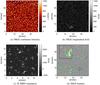 |
Fig. 1 a) IMaX continuum image. b) IMaX longitudinal field obtained from SIR inversions. c) MHD simulation: longitudinal component of the magnetic field. d) IMaX features tracking example. The region between the two concentric circles, in the lower-right part of the image, illustrates the size of the aperture placed around each magnetic element to determine the properties of the p-mode oscillations near that magnetic element. Each coloured contour represents a label given to each identified magnetic feature (see main text). The inset displays a blow-up of a part of the field of view, including the left part of the large network patch near the bottom of the full image. |
The small-scale magnetic features are expected to harbour a rich variety of waves excited largely by the buffeting they experience at the hands of the granulation and partly by their interaction with the ubiquitous p-modes. Hasan et al. (2003) argued that horizontal motion of magnetic elements in the photosphere can generate enough wave energy to heat the magnetized chromosphere. They found, based on numerical modelling, that granular buffeting excites kink waves and, through mode coupling, longitudinal waves. This was confirmed by Musielak & Ulmschneider (2003b). They argued that although transverse tube waves do not generate observable Doppler signals, when observing vertical flux tubes at disc centre, they excite forced and free longitudinal oscillations through non-linear coupling. These should be observable if data with sufficiently high spatial resolution and sensitivity are available.
From the observational point of view, Volkmer et al. (1995) detected short-period longitudinal waves (P ≃ 100 s) in small magnetic elements in the solar photosphere using high spatial and temporal resolution spectropolarimetric data and estimated the energy flux they carried to be sufficient to heat the bright structures observed in the chromospheric network. Using SUNRISE/IMaX data, Martínez González et al. (2011) have found magnetic flux density oscillations in internetwork magnetic elements, which they interpreted as the result of granular forcing.
In this work, we study the longitudinal and transversal oscillations of small magnetic elements in the solar photosphere and their power spectra. To do this, we exploit the unprecedented combination of high spatial and temporal stability provided by SUNRISE/IMaX, together with the large number of observed magnetic features, to infer statistically significant information on oscillations of small-scale flux tubes and the interaction between longitudinal waves and transverse kink waves. A particular advantage of this approach is the proven ability of SUNRISE to resolve small magnetic elements (Lagg et al. 2010), thereby detecting some of the internal structure of network features (Martínez González et al. 2012).
This paper is organized as follows. In Sect. 2 we outline the data set used in this work, as well as the magnetohydrodynamic (MHD) simulation used to check the validity of our observational results. In Sect. 3, we describe the method used for the analysis of the oscillations which is based on fast Fourier transform (FFT) analysis and wavelet analysis. In Sect. 4, we present the results. Starting from the FFT power spectra obtained from a limited number of magnetic features, we then apply wavelet analysis to a single magnetic element as a case study and then extend this analysis to the full sample of magnetic features at our disposal to obtain statistically significant phase lag information between the longitudinal and transversal velocity. Section 5 is devoted to the discussion of the results, while our conclusions are given in Sect. 6.
2. Data sets employed: SUNRISE/IMaX observations and MHD simulations
The data set used in this work consists of a two-dimensional (2D) spectropolarimetric time series with a length of approximately 32 min and a cadence of 33 s, acquired by the Imaging Magnetograph eXperiment (IMaX; Martínez Pillet et al. 2011) on board the SUNRISE balloon-borne mission (Barthol et al. 2010) in the Fe I 525.02 nm spectral line. The data were taken on 2009 June 9 and encompass a quiet Sun region of approximately 40 × 40 arcsec close to the disc centre. In addition to common calibrations, the data were phase-diversity reconstructed (Solanki et al. 2010; Martínez Pillet et al. 2011), resulting in a spatial resolution of 0.15–0.18 arcsec. The calibration procedure of IMaX data is summarized by Roth et al. (2010), although we used spectropolarimetric inversions instead of a Gaussian fit to estimate the Doppler velocity in small magnetic elements. There is an intrinsic advantage in doing this. In magnetic elements, the Gaussian fit can often fail as the Stokes-I signal is reduced. The inversions, however, also include Stokes-V profiles, which are in turn very strong. The zero crossing wavelength point of Stokes-V is a velocity indicator available to the inversion code but not to the Gaussian fits. For more details on the spectropolarimetric inversions we refer to Guglielmino et al. (2012). In Fig. 1 we plot the continuum intensity map (panel a) and the longitudinal magnetic field (panel b) estimated by means of SIR spectropolarimetric inversions (Ruiz Cobo & del Toro Iniesta 1992), assuming a single-component atmosphere with a height-independent magnetic vector.
The MHD simulations analysed here were carried out using the MURaM code which solves the compressible MHD equations with an energy equation including radiation transfer in a non-grey approximation, and an equation of state which includes the effects of partial ionization (see Vögler et al. 2005, for a full description of the equations and the numerical details). The code has been used in quiet-Sun studies (e.g. Keller et al. 2004; Vögler & Schüssler 2007), as well as in studies of magnetic structures (for example pores, Cameron et al. 2007, sunspots Rempel et al. 2009, and active regions Cheung et al. 2007 amongst others). Here we use a simulation domain which is 24 Mm in both horizontal directions and 1.4 Mm in the vertical direction. The grid spacing is 20.8 km in both horizontal directions, and 14 km in the vertical. The top boundary is open to flows, and the magnetic field there is forced to be vertical. In this study we only use the vertical magnetic field and vertical velocity from the τRoss = 1 surface (at a height of about 800 km above the bottom of the box), which was stored every 5 to 7 s. The total duration is 58 min in total.
3. Methods
3.1. Features tracking
With the aim of studying the properties of the oscillations in small magnetic structures, we tracked the magnetic features in both the simulation and the IMaX data using the Yet Another Feature Tracking Algorithm (YAFTA) code, a labelling flux-ranked uphill gradient algorithm (Welsch & Longcope 2003; DeForest et al. 2007). The algorithm tracks and labels groups of pixels lying on the same hill in circular polarization maps in the case of IMaX data, and vertical magnetic field maps in the case of simulations. For this purpose we set up two thresholds to avoid spurious detections in the final results. The first detection threshold is set at 2σ to both Stokes V maps and Bz maps, where for the observations the σ value corresponds to the noise at the IMaX continuum wavelength, whereas for the simulations it corresponds to the standard deviation of the magnetic signal over the FoV. It is worth mentioning here that the choice of σ may affect the final results of our investigation. For this reason we also did a sensitivity test using different thresholds (see Sect. 4.3). The second threshold acts spatially, allowing the detection of only those magnetic features whose area is larger than 9 pixels (slightly larger than the spatial resolution achieved) in the case of IMaX data, and 49 pixels for the MHD simulation. These two values correspond to a linear spatial scale of 150 km and 140 km, respectively. These thresholds have been chosen in such a way that the distributions of size of the magnetic elements in the simulation and in the IMaX data are comparable (see Fig. 2). The size of each magnetic element is computed as the equivalent diameter of the circle with the same area as the measured one. The position of each tracked magnetic element is obtained from the centre of gravity, and the velocity is then estimated.
As extensively discussed in Jafarzadeh et al. (2013), the quantity | Bcos(γ) |, with γ being the magnetic field inclination, is retrieved more reliably than B alone, since B can be affected by the noise in Stokes Q and U. For this reason the use of Stokes V maps in the case of IMaX observations is preferred. We are aware, however, that using Bz for the simulations and Stokes V for the observations does introduce a certain bias. Thus, we expect that we chose fewer strong-field features in the observations, since these generally show a significant line-weakening because of the high temperature (e.g. Solanki 1986; Lagg et al. 2010).
The visual inspection of the results of the tracking revealed a number of short-lived magnetic features which were observable (traceable) for only a few time steps. Therefore, an additional temporal threshold was added to exclude them from the analysis, since we are mainly interested in improving the frequency resolution in the spectral domain. All the features lasting for less than 150 s in both the simulation and the observational data set were rejected. In Fig. 1 (panel d) we mark the features fulfilling the criteria in a SUNRISE/IMaX snapshot with coloured contours. Each colour represents a label given to the identified features. The inset highlights that the algorithm tends to break up larger magnetic features into smaller ones, according to the number of maxima of the signal present there.
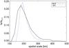 |
Fig. 2 Histograms of the size of the analysed magnetic elements in the IMaX data (continuous line) and in the simulation (dashed line). The size of each magnetic element is defined as the equivalent diameter associated to a circle with the same area as the measured one. |
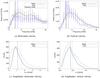 |
Fig. 3 a) Power spectra of vh obtained from IMaX (solid line) and simulations (dashed line). The dot-dashed line represents the average power spectrum of 500 simulated random walks. b) Power spectra of vz obtained from IMaX and simulations. Each spectrum is the average of spectra of twenty individual features. The vertical continuous and dashed lines indicate the lowest frequency due to the total length of the time series for the vertical velocity and the horizontal velocity, respectively. c) Amplitudes of vh. d) Amplitudes of vz. The vertical continuous and dashed lines indicate the mean value for IMaX and the simulation, respectively. |
3.2. Analysis of the oscillations
For each magnetic element tracked by the algorithm, we estimated the vertical velocity (vz) within its area by averaging values from each individual pixel and the horizontal velocity (vh) obtained by following its position. The vertical velocity corresponds closely to the line of sight (LoS) velocity in the case of IMaX data, since the FoV is very close to the disc centre. The Doppler velocity was taken from the SIR inversions. In addition, we also estimated the contribution of the local non-magnetic oscillatory field (vLNM) by considering the surroundings of each magnetic element to further check the results. To this end, we surrounded each magnetic element with an aperture like the one shown in Fig. 1 (lower-right part of panel d) between the concentric circles with inner and outer radii of 380 km and 950 km, respectively. The ambient oscillatory signal vLNM is estimated by taking the average of the velocity of the non-magnetic pixels (below 10 G) within the defined aperture. This prevents the contamination by possible magnetic field effects.
Our analysis consists of three steps. First, we selected suitable magnetic features on the basis of their lifetimes to estimate the average power spectral density for both longitudinal and transversal velocity oscillations. We chose twenty cases for simulations and for observations with similarly long lifetimes. We restricted ourselves to a few examples, picking particularly long-lived magnetic features that can also harbour lower frequency waves, unlike the short-lived majority of the magnetic features. For each magnetic feature we estimated the periodogram using the Welch method (Blackman & Tukey 1958). Each periodogram is then interpolated over the same frequency grid, to take into account the different lengths of the time series used, although the lengths of the time series chosen was very similar (on average ~12–13 min). We then estimated the average power spectral density for both longitudinal and transversal oscillations. In this case the simulation was resampled to the IMaX cadence (33 s).
In the second step of our analysis, we took the longest lived magnetic feature among the twenty chosen before as a case study. The amplitude of the oscillations of vz and vh, as well as their coherence and phase were studied using wavelets. Since the time series associated to the transverse and longitudinal velocity are expected to be non-stationary, the wavelet analysis presents many benefits over the Fourier-based analysis, in particular with respect to the estimate of the phase (Bloomfield et al. 2004). Our analysis was performed with the standard tool by Torrence & Webster (1999). We used the complex Morlet mother function, which is also suitable for estimating the phase between two signals. In addition, we also made use of the coherence spectrum. While the wavelet spectrum gives information about the distribution of power in the frequency-time domain, the coherence of two time series, which is dependent on the cross-wavelet transform, is useful for investigating the interaction between the two physical mechanisms (Torrence & Webster 1999), in our case between vh and vz.
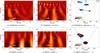 |
Fig. 4 a) Wavelet amplitude spectrum of vz from the simulation. b) Wavelet amplitude spectrum of vh from the simulation. c) Wavelet phase coherence spectrum between vz and vh from the simulation. The arrows represent the phase lag in polar coordinates (zero phase corresponds to arrows pointing to the right). d) Wavelet amplitude spectrum of vz from IMaX. e) Wavelet amplitude spectrum of vh from IMaX. f) Wavelet phase coherence spectrum between vz and vh from IMaX. The arrows represent the phase lag in polar coordinates (zero phase corresponds to arrows pointing to the right). The dashed line represents the cone of influence where results cannot be trusted (area between the dashed lines and the edges of the diagram). The white contours represent the 95% confidence level. |
The third and final step of our analysis represents an extension of the second step to the full population of magnetic features. In particular, we focussed on the phase angle between vh and vz.
The total number of features tracked in the IMaX data and the simulation amounts to 2384 and 6388, respectively. The greater number of features tracked in the simulation can be explained in terms of a combination of effects. Thus, the estimated average lifetime of the magnetic elements in the simulation is 2.5–3 times smaller than the average lifetime of the magnetic features collected in the IMaX data. This, together with the longer duration of the simulation (58 min) compared to the IMaX data (32 min) and the intrinsic higher spatial resolution of the simulation, can significantly increase the number of features collected.
Our goal is to obtain the distribution of the phase difference between the transversal and longitudinal velocity inside the magnetic elements. A clear phase relation would point to an interaction between horizontal and vertical velocity perturbations. A number of constraints, described below, were applied on the feature to ensure the reliability of the results.
For each magnetic feature we selected the location in the frequency-time domain at which the two time series under investigation show the highest coherence; this can be seen in the coherence diagram given by the wavelet analysis. The phase between the two signals is then estimated at this location. A phase estimate was considered only if the coherence between the two signals under investigation was above 0.8 outside the cone of influence of the wavelet phase diagram, i.e. in the region where the wavelet analysis can be trusted. The temporal cadence of the simulations was reduced to match the IMaX cadence (33 s).
Besides determining the phase shift between the longitudinal velocity vz and the transversal velocity vh, we repeated the analysis between the surrounding oscillatory field vLNM and vh. This is done to check whether or not the phase relation between the longitudinal and transversal velocity is strictly inherent to the wave signal observed inside the magnetic elements. In addition, we also studied the distribution of periods at which vz and vh are coherent. This is done to find the frequency band at which their interaction (if any) takes place.
4. Results
4.1. FFT power spectra and amplitude of oscillations
Through the features tracking we obtained the horizontal and vertical velocity associated to each magnetic element. As mentioned in Sect. 3.2, we first estimated the average power spectra of the twenty magnetic features with the longest lifetimes. In panels a and b of Fig. 3, we show the power spectra obtained from the IMaX data and the simulation. The power spectrum for both horizontal velocity (panel a) and vertical velocity (panel b) are shown. The vertical line indicates the poorer frequency resolution among the time series chosen (i.e. the frequency resolution of the shortest time series νmin = 2/Tlength); therefore the region at low frequency below this line should not be trusted. Both simulation and observations display a similar behaviour. The power spectrum of vz shows that most of the power is concentrated at low frequency, in the 2–7 mHz band.
The horizontal velocity, in turn, is characterized by a broader power spectrum with high-frequency components (>8–10 mHz), although the highest power is still located in the low frequency band. The power of the horizontal velocity is larger than the power of vz at all frequencies, particularly in the IMaX data. Consequently, the amplitude of the vh oscillations is larger. This can be seen in panels c and d of Fig. 3 where we plot the distributions of the standard deviation of vh and vz obtained from the complete population of magnetic features. Both simulations and observations agree very well with, with most of the magnetic features displaying horizontal oscillations having a mean amplitude around 1–1.5 km s-1, while for the longitudinal velocity, the corresponding values lie in the range 0.4–0.5 km s-1.
4.2. Wavelet amplitude analysis and coherence: a case study
Figure 4 depicts the wavelet diagrams for the two longest time series found respectively in the IMaX data and in the simulation domain (i.e. the longest-lived magnetic element in each). The time series associated with the magnetic element found in the IMaX data has been truncated to match the lifetime of the magnetic element from the simulation. This is to force the wavelet diagrams to be comparable in terms of frequency resolution.
Panels a and d show the amplitude spectrum of vz for the simulation and the observations, respectively. Panels b and e show the amplitude spectrum of vh and panels c and f the coherence between vz and vh. The arrows represent the phase angle between the two signals in polar coordinates, where zero is along the x-axis. In our sign convention, a negative phase angle (arrows pointing down) means that vh precedes vz. In the same plots, the white contour represents the 90% confidence level, while the dashed line represents the cone of influence.
The vertical velocity, vz, is characterized in both the simulation and the IMaX data by oscillations with periods larger than 130–150 s. It is worth noting that, although the fiducial line extends to longer periods in the three-minute band, only the region outside the cone-of-influence can be trusted and, therefore, only this region will be considered in our analysis.
The horizontal velocity vh of the magnetic elements shows power in the band P = 100–150 s and at higher frequency. In the simulation, where the Nyquist frequency is larger, one finds many peaks above the confidence level close to P = 50 s or even smaller periods. This result agrees with the power spectral density (Sect. 4.1).
In both the simulation and the IMaX data, one finds locations in the wavelet diagram where vz and vh are highly coherent (see panels c and f of Fig. 4). As the coherence is a measure of the interaction between two signals, which depends on the cross-spectrum, one can find high coherence even outside the confidence levels of each time series. This means that even when there is minimal power the processes associated to the vertical and horizontal velocity may still strongly interact.
A high coherence is found at periods of 100 s and shorter. The associated phase angle is always different from 0°. In the simulation the phase lag is in the range (− 70°, − 110°), while for IMaX data it is close to − 95°.
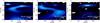 |
Fig. 5 Power spectra of three different simulated random walks. The continuous line represents the 95% confidence level, the dashed line represents the cone of influence. The Nyquist period is set by the sampling to 66 s. |
4.3. Power spectrum of random walks
Small flux tubes in the photosphere are subject to the forcing action of the granular flows; therefore their displacements and oscillations represent the response to this forcing. In this section we present the results of a simulation conducted to test whether the vh power spectra are compatible with random walks.
We simulated the paths of 500 2D random walks lasting for 2000 s and with a temporal step of 1 s. The physical size of the spatial grid was set to 0.5 km. This is equivalent to setting the amplitude of the fluctuation of the position in the time interval. This value was chosen a posteriori to ensure that the mean amplitude of vh of the simulated random walks was ≃1.3 km s-1, thus similar to the real one at the same IMaX cadence (after resampling the simulated time series at 33 s). After setting up this value, we repeated the simulation. For each random walk we estimated the power spectrum of vh. In Fig. 3 (panel a) we plot the average power spectrum obtained from averaging over all the 500 cases with a dot-dashed line. The shape of the power spectra are similar, thus the observed oscillations of the flux tubes appear to be consistent with random walk displacements due to buffeting. For comparison with the real case discussed in the previous section, in Fig. 5 we also show three examples of wavelet diagrams obtained from the simulated random walks. The power is distributed over a broad range of periods, from large periods at the frequency resolution imposed by the duration of the simulated time series, down to the Nyquist limit (66 s).
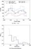 |
Fig. 6 a) Histogram of phase φ(vz − vh) obtained from IMaX with different thresholds (2σ black continuous line, 3σ red dash-dot line, and 4σ dotted line), and the simulation (dashed line). Crosses represent the histogram of phase obtained from IMaX data tracking of contiguous pixels instead of local maxima. b) Normalized histogram of the periods at which the coherence between vz and vh is largest for IMaX (continuous line) and the simulation (dashed line). |
4.4. Statistical analysis: histograms of phase
To find a statistically reliable estimate of the phase relation φ(vz − vh), we used the full sample of tracked magnetic elements. For this purpose, we used the wavelet analysis described in Sect. 4.2 to estimate the phase corresponding to the highest coherency in the wavelet diagram, for each tracked magnetic element. In Fig. 6a we compare the results obtained from the IMaX observations (continuous line) to those from the MHD simulation, resampled to match the IMaX cadence (dashed line). Both histograms display clear maxima at − 90° and + 90°.
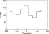 |
Fig. 7 Histogram of phase φ(vh − vLNM) obtained from IMaX data. |
To test the consistency of this result, we studied the phase relation between the horizontal velocity and the longitudinal velocity surrounding the magnetic elements. The aim of this test is to check whether the ± 90° phase angle is inherent to the velocity signal strictly inside the magnetic elements, or affected by contaminations due to the surrounding acoustic field or some issue concerning the analysis. To this end we estimated the mean velocity signal in an annular region like that shown in Fig. 1d, where we selected only the non-magnetic pixels. The results of this check are plotted in Fig. 7. The phase lag is zero in this case. This result demonstrates that the ± 90° phase lag between the vertical and horizontal velocities is obtained only if the internal velocity field of the flux tube is considered. Therefore, it is closely related to the nature of the MHD waves in the magnetic elements. As mentioned in the previous section, we tracked groups of pixels lying on the same hill. This method tracks each magnetic element (a peak in the Stokes V signal) separately, even if it is part of a tight cluster (i.e. the magnetic signal stays high between individual elements). Clusters of magnetic elements may have a correlated horizontal velocity, hence their contribution to the histogram of phase may significantly affect its shape. To further test our results, we studied the histogram of phase obtained from the IMaX data, but we tracked contiguous pixels instead of local maxima. Thus, we considered all the contiguous pixels with Stokes V above a given threshold to belong to a single magnetic feature. In this case, regardless of the presence of local maxima, the magnetic structure is tracked as a whole. The resulting histogram is also shown in Fig. 6a (crosses). Even in this case the histogram of phase shows two maxima at −90° and +90°.
We also note that a significant fraction of elements show a small phase shift (~23% in the IMaX case). This can be due to projection effects. If a magnetic feature is inclined to the LoS, there will be a component of the transverse velocity associated to the observed kink oscillations along the LoS which will be vz,projected = vhsin(γ), where γ is the inclination angle. By the same token, the amplitude of the kink velocity will be decreased by cosγ.
If we consider the average observed horizontal velocity (see Fig. 3) after the correction for the projection effects we get vz,projected ~ 0.19−0.29 km s-1. This is estimated using an inclination angle between 10° and 15°, as obtained by Jafarzadeh et al. (in prep.) from IMaX observations.
From the histogram of the LoS velocity we can estimate the probability of finding a magnetic element with vh smaller than the above limits. This corresponds to the case in which the longitudinal velocity would be dominated by the projection of the horizontal velocity along the LoS, so they would be in phase. We estimate this probability between 14% and 29%, which is comparable with the observed fraction of elements with a small phase shift. It must be noted that our selection criteria based upon Stokes V and Bz in the IMaX data and the simulation, respectively, may result in a sample of magnetic features not restricted to vertical flux tubes, including a significant fraction of inclined features for which φ(vz − vh) is close to zero because of the mechanism above. However, this may not be the only mechanism responsible for the large spread of the peaks in the histogram of phase. Another important cause may be the difference in the height of maximum response of Stokes V to vertical and horizontal velocities in the magnetic elements. Along with the first mechanism cited above, this mechanism may contribute to increasing the number of elements with small phase lag.
Moreover, as anticipated in Sect. 3.1, we checked the results against possible effects due to the particular choice of the threshold used in the tracking code. In Fig. 6 we also plot the results of this analysis using a threshold of 2σ, 3σ, and 4σ on the IMaX data. As expected the histograms are shifted to lower values as the threshold increases, but their shape is not changed, showing again two maxima at −90° and +90°.
We also studied the distribution of periods at which one finds the highest coherence between vz and vh, that is periods at which the ±90° phase lag is found. We recall here that we only considered those cases in which the coherence was at least 0.8. This is a demanding constraint. This distribution is shown in Fig. 6b. The continuous line represents the IMaX data, the dashed line the simulation. It is evident that in most of the cases the interaction between the vertical and the horizontal velocity takes place in the high-frequency band at periods smaller than 200 s.
5. Discussion
Our results concern the main properties of velocity perturbations in small magnetic elements in the solar photosphere. In particular, we have studied transverse oscillations and longitudinal velocity oscillations of these magnetic elements. Starting from the longest time series associated with different magnetic features, we have retrieved the average power spectral density for the two kinds of oscillations. Since most of the magnetic features tracked, and their associated time series, have a short lifetime (shorter than 10 min), the wavelet analysis constitutes a more suitable tool for the analysis of the periodicities and, more specifically, for the estimate of the phase angle between vz and vh. This is even more important when dealing with non-stationary signals like those expected for these kinds of velocity oscillations.
Our results demonstrate that, while vz is characterized by comparatively low frequency oscillations (ν < 7–8 mHz, i.e. periods larger than 120–140 s) and amplitudes of the order of 500 m/s, transverse displacements have a more extended power spectrum with very high frequency peaks (ν ~ 8–10 mHz, i.e. periods of 120–100 s), and with amplitudes of the order of 1 km s-1. Both these modes are expected to be propagating at these frequencies with significant observed power.
The wavelet analysis has also revealed that the horizontal velocity is characterized by high frequency wave packets, confirming the non-stationarity of the signals. Unfortunately, the short lengths of the individual time series, because of the short lifetimes of the magnetic features, hampered the estimate of the mean duration of these packets, and the resolution of the low frequency part of the spectra.
We have also demonstrated that at least the vh power spectra associated to the longest-lived magnetic elements are compatible with those of random walks. Manso Sainz et al. (2011) have shown that once small magnetic elements reach the intergranular lanes they are subject to the buffeting action of the surrounding granular and integranular turbulent flows and they follow random walks. However, photospheric magnetic elements may have ballistic trajectories before entering the intergranular lanes. Additionally, we used the coherence to investigate the interaction between the transverse velocity and the longitudinal perturbations. From the analysis we have found that in most of the cases a high coherence is found in the high frequency band (P < 200 s). This demonstrates that the vertical and the horizontal velocity are strongly coupled and interacting at high frequency. This interaction is also characterized by a phase lag. The statistical analysis has shown that the phase difference φ(vz − vh) is found to be ±90°. It is not possible to solve the ambiguity which is inherent to our methodology. Note that only those cases in which the coherence was above a very high threshold (0.8) were considered, thus strengthening the reliability of the results.
This result demonstrates that buffeting-induced displacements of the flux tubes are accompanied by, and possibly excite, longitudinal and compressive MHD waves. Jafarzadeh et al. (in prep.) have found, using multi-wavelength observations, obtained from Sunrise/SuFI that small magnetic elements are mainly dominated by fast MHD waves with velocity of the order of 40 km s-1, and by kink waves with velocities in the same range. Both kinds of waves were upward propagating. This scenario is also supported by numerical simulations (Nutto et al. 2012). On the other hand, Jess et al. (2012b) have also detected slow upward propagating longitudinal waves in small magnetic elements, using high-cadence broadband 2D data, visible as periodic intensity fluctuations in the range 110–600 s.
Nakariakov & Verwichte (2005) have reviewed in detail the excitation of waves in a magnetic cylinder. They have shown, by means of numerical simulations, that kink waves and longitudinal compressive waves which are excited by the horizontal motion of the flux tube itself (see for example their Fig. 4 and the associated movie1), may coexist in the same flux tube. In particular, the kink mode excites a longitudinal density perturbation, whose maximum is reached at the inversion points of the flux tube’s horizontal motion (i.e. when the horizontal velocity is zero). The longitudinal perturbations and the horizontal velocity are therefore 90° out of phase. Although our results are consistent with this scenario, we believe that the phase shift alone is not enough to uniquely identify the mode of oscillation. This is because the vertical velocity in both the observations and the realistic MHD simulations used is probably the result of a mixture of modes whose superposition hinders their identification.
The interaction and, therefore, the energy exchange between the kink mode and the longitudinal mode takes place over a wide range of frequencies (see Fig. 6 panel b), and are more probable at high frequencies (P < 100 s). At the frequencies of interaction, the power spectra of both kink oscillations and longitudinal oscillations show less power than the low-frequency band. It is worth stressing that transverse perturbations and the longitudinal mode can interact even when the power is below the maximum power achieved in the power spectrum associated with each time series. In other words, in order for the two modes to interact, it is not necessary to have a large amount of power at the same time and at the same frequency in both processes. Although the amount of energy per unit frequency is small in this case, Fig. 6 demonstrates that this interaction can take place over a wide range of frequencies (possibly even at frequencies above the Nyquist frequency imposed by the cadence of our observations), thus the total amount of energy involved could be significantly larger.
These results rely strongly on the coherence and the phase estimates. Giving an estimate of the confidence level of the power peaks in the wavelet diagram is straightforward; unfortunately, this is not true for the phase. The major problem is, in the case of pure noise, that there is no reference value for the angle, which is a variable uniformly distributed from − π to + π. For this reason, we have provided a statistical check of our phase estimate by exploiting the large number of magnetic elements at our disposal. This not only proves the reliability of the phase relation between vz and vh, but also underlines the general character of this result, which holds for a significant fraction of magnetic elements.
We have also checked whether this phase relation is found only when considering the velocity field inside the magnetic features or, rather, also obtained when the vertical velocity outside the magnetic elements (vLNM) is considered. This check has demonstrated that the ± 90° phase can only be obtained in the first case. This basically means two important things. Firstly, our phase estimate is not affected by contamination through the acoustic field surrounding the magnetic elements. Secondly, the results seen so far are closely related to the MHD waves present in small magnetic features and are not significantly affected by spurious effects coming from the external velocity field. This means that we are really taking advantage of the high spatial resolution provided by SUNRISE, which allows us to isolate the oscillation field inside small-scale magnetic elements.
We compared the observational results with radiative-MHD simulations, and we found them in excellent agreement. This demonstrates the reliability of the IMaX results and puts our findings on a firmer ground.
The phase histograms could suffer from the presence of a bias because of the inability to track magnetic features for a long time. This is most likely due to the short lifetimes of the magnetic features, although we cannot rule out detection problems in some cases (e.g. when a magnetic feature is lost or confused due to interactions with other features). Therefore, longer lived magnetic features could host a lot more power in longer-period oscillations. From the theoretical point of view, the presence of detectable longitudinal velocity oscillations inside the flux tubes, associated with buffeting-induced transverse perturbations, is in agreement with the theoretical work by Hasan et al. (2003) and Musielak & Ulmschneider (2003b) who computed that the horizontal displacement of the flux tubes due to the external forcing by granular buffeting not only generates transverse oscillations, but also longitudinal oscillations, which should then be observable inside the magnetic structures as Doppler velocity oscillations. This scenario is in good agreement with our findings. Moreover, our results give new insight into the interaction between longitudinal and transverse perturbations and constitutes the first observational evidence of the interaction between them in solar magnetic features. One way to distinguish random horizontal motions of flux tubes from (propagating) kink waves would be to look at different heights simultaneously. In this case, for non-vanishing phase lags this would indicate the presence of propagating waves. One may think that if a tube is displaced by convection in the deeper layers in one horizontal direction, it will move first in the lower layers then in the upper layers, mimicking a propagating wave. However, this motion may set up a propagating kink wave.
6. Conclusions
In this paper we have reported the main properties of MHD waves and perturbations in small-scale magnetic elements by comparing high-resolution SUNRISE/IMaX observations to MHD simulations. This analysis reveals the interaction between transverse perturbations and longitudinal velocity oscillations in small-scale magnetic elements.
We find that small-scale magnetic features in the solar photosphere host a rich variety of MHD perturbations which we studied by means of a statistical approach. Our analysis has demonstrated that most of the magnetic elements observed display transversal oscillations with amplitudes of the order of 1 km s-1, and with a power spectrum which extends to very high frequencies (ν > 10 mHz). The longitudinal waves found in the data are characterized by a lower frequency (ν < 7–8 mHz). Although their power spectra present peaks at different positions, the interaction between kink displacements and longitudinal waves is, with high confidence level, found to take place in the range P < 200 s. In particular, we found that the Doppler velocity signal within the magnetic features shows a preference for ± 90° phase shift with respect to the horizontal velocity of the magnetic feature itself.
This result is only obtained if the velocity signal inside the magnetic elements is considered, thus ruling out the contamination from the external non-magnetic oscillatory field. These results agree with the theoretical framework in which kink waves generated by granular buffeting are accompanied by longitudinal waves generated through non-linear interactions.
Small-scale magnetic fields cover a significant fraction of the solar surface, therefore the presence of MHD waves and their energy exchange may assume a remarkable importance in the energy transportation toward the upper layers of the Sun’s atmosphere. This work has profited greatly from the high resolution and the absence of seeing characterizing the SUNRISE data, which make them ideal for studying time-dependent phenomena. New high spatial resolution and simultaneous multi-line spectropolarimetric observations of the solar quiet photosphere and chromosphere are needed to reveal clues about the propagation of these MHD waves in small-scale flux tubes. Furthermore, our results emphasize the need for very high temporal cadence (<30 s) data in order to resolve the very high frequency portion of the power spectrum.
The movie of the simulation is available online at the following link: http://solarphysics.livingreviews.org/Articles/lrsp-2005-3/resources/cylindermodes/fast_m1_b0_running/java_movieplayer_trans.html
Acknowledgments
We thank Lluis Bellot Rubio for providing the SIR inversions of the IMaX data. We also thank Laurent Gizon, Hannah Schunker, and Aaron Birch for useful discussions. M.S. thanks Francesco Berrilli for useful discussions and comments. The German contribution to Sunrise is funded by the Bundesministerium für Wirtschaft und Technologie through Deutsches Zentrum für Luft- und Raumfahrt e.V. (DLR), Grant No. 50 OU 0401, and by the Innovationsfond of the President of the Max Planck Society (MPG). The Spanish contribution has been funded by the Spanish MICINN under projects ESP2006-13030-C06 and AYA2009-14105-C06 (including European FEDER funds). The HAO contribution was partly funded through NASA grant NNX08AH38G. This work has been partly supported by the WCU grant (No. R31-10016) funded by the Korean Ministry of Education, Science and Technology.
References
- Barthol, P., Gandorfer, A., Solanki, S. K., et al. 2010, Sol. Phys., 268, 1 [Google Scholar]
- Blackman, R. B., & Tukey, J. W. 1958, The measurement of power spectra from the point of view of communications (Dover Publications) [Google Scholar]
- Bloomfield, D. S., McAteer, R. T. J., Lites, B. W., et al. 2004, ApJ, 617, 623 [NASA ADS] [CrossRef] [Google Scholar]
- Bonet, J. A., Cabello, I., & Sánchez Almeida, J. 2012, A&A, 539, A6 [NASA ADS] [CrossRef] [EDP Sciences] [Google Scholar]
- Cameron, R., Schüssler, M., Vögler, A., & Zakharov, V. 2007, A&A, 474, 261 [NASA ADS] [CrossRef] [EDP Sciences] [Google Scholar]
- Centeno, R., Collados, M., & Trujillo Bueno, J. 2009, ApJ, 692, 1211 [NASA ADS] [CrossRef] [Google Scholar]
- Cheung, M. C. M., Schüssler, M., & Moreno-Insertis, F. 2007, A&A, 467, 703 [NASA ADS] [CrossRef] [EDP Sciences] [Google Scholar]
- DeForest, C. E., Hagenaar, H. J., Lamb, D. A., Parnell, C. E., & Welsch, B. T. 2007, ApJ, 666, 576 [NASA ADS] [CrossRef] [Google Scholar]
- De Pontieu, B., Erdélyi, R., & James, S. P. 2004, Nature, 430, 536 [NASA ADS] [CrossRef] [PubMed] [Google Scholar]
- Edwin, P., & Roberts, B. 1983, Sol. Phys., 88, 179 [NASA ADS] [CrossRef] [Google Scholar]
- Fedun, V., Shelyag, S., & Erdélyi, R. 2011, ApJ, 727, 17 [NASA ADS] [CrossRef] [Google Scholar]
- Guglielmino, S. L., Pillet, V. M., Bonet, J. A., et al. 2012, ApJ, 745, 160 [NASA ADS] [CrossRef] [Google Scholar]
- Hasan, S. S., Kalkofen, W., van Ballegooijen, A. A., & Ulmschneider, P. 2003, ApJ, 585, 1138 [NASA ADS] [CrossRef] [Google Scholar]
- Jafarzadeh, S., Solanki, S. K., Feller, A., et al. 2013, A&A, 549, A116 [NASA ADS] [CrossRef] [EDP Sciences] [Google Scholar]
- Jess, D. B., Mathioudakis, M., Erdélyi, R., et al. 2009, Science, 323, 1582 [NASA ADS] [CrossRef] [PubMed] [Google Scholar]
- Jess, D. B., Pascoe, D. J., Christian, D. J., et al. 2012a, ApJ, 744, L5 [NASA ADS] [CrossRef] [Google Scholar]
- Jess, D. B., Shelyag, S., Mathioudakis, M., et al. 2012b, ApJ, 746, 183 [NASA ADS] [CrossRef] [Google Scholar]
- Keller, C. U., Schüssler, M., Vögler, A., & Zakharov, V. 2004, ApJ, 607, L59 [NASA ADS] [CrossRef] [Google Scholar]
- Khomenko, E., Centeno, R., Collados, M., & Trujillo Bueno, J. 2008a, ApJ, 676, L85 [NASA ADS] [CrossRef] [Google Scholar]
- Khomenko, E., Collados, M., & Felipe, T. 2008b, Sol. Phys., 251, 589 [NASA ADS] [CrossRef] [Google Scholar]
- Lagg, A., Solanki, S. K., Riethmüller, T. L., et al. 2010, ApJ, 723, L164 [NASA ADS] [CrossRef] [Google Scholar]
- Manso Sainz, R., Martínez González, M. J., & Asensio Ramos, A. 2011, A&A, 531, L9 [NASA ADS] [CrossRef] [EDP Sciences] [Google Scholar]
- Martínez González, M. J., Asensio Ramos, A., Manso Sainz, R., et al. 2011, ApJ, 730, L37 [NASA ADS] [CrossRef] [Google Scholar]
- Martínez González, M. J., Bellot Rubio, L. R., Solanki, S. K., et al. 2012, ApJ, 758, L40 [NASA ADS] [CrossRef] [Google Scholar]
- Martínez Pillet, V., Del Toro Iniesta, J. C., Álvarez-Herrero, A., et al. 2011, Sol. Phys., 268, 57 [NASA ADS] [CrossRef] [Google Scholar]
- Musielak, Z. E., & Ulmschneider, P. 2003a, A&A, 400, 1057 [NASA ADS] [CrossRef] [EDP Sciences] [Google Scholar]
- Musielak, Z. E., & Ulmschneider, P. 2003b, A&A, 406, 725 [NASA ADS] [CrossRef] [EDP Sciences] [Google Scholar]
- Musielak, Z. E., Rosner, R., & Ulmschneider, P. 1989, ApJ, 337, 470 [NASA ADS] [CrossRef] [Google Scholar]
- Nakariakov, V. M., & Verwichte, E. 2005, Liv. Rev. Sol. Phys., 2, 3 [Google Scholar]
- Narain, U., & Ulmschneider, P. 1996, Space Sci. Rev., 75, 453 [NASA ADS] [CrossRef] [Google Scholar]
- Nutto, C., Steiner, O., Schaffenberger, W., & Roth, M. 2012, A&A, 538, A79 [NASA ADS] [CrossRef] [EDP Sciences] [Google Scholar]
- Rempel, M., Schüssler, M., Cameron, R. H., & Knölker, M. 2009, Science, 325, 171 [NASA ADS] [CrossRef] [PubMed] [Google Scholar]
- Roberts, B. 1983, Sol. Phys., 87, 77 [NASA ADS] [CrossRef] [Google Scholar]
- Roberts, B., & Webb, A. R. 1978, Sol. Phys., 56, 5 [NASA ADS] [CrossRef] [Google Scholar]
- Roth, M., Franz, M., Bello González, N., et al. 2010, ApJ, 723, L175 [NASA ADS] [CrossRef] [Google Scholar]
- Ruiz Cobo, B., & del Toro Iniesta, J. C. 1992, ApJ, 398, 375 [NASA ADS] [CrossRef] [Google Scholar]
- Solanki, S. K. 1986, A&A, 168, 311 [NASA ADS] [Google Scholar]
- Solanki, S. K., Inhester, B., & Schüssler, M. 2006, Rep. Prog. Phys., 69, 563 [NASA ADS] [CrossRef] [Google Scholar]
- Solanki, S. K., Barthol, P., Danilovic, S., et al. 2010, ApJ, 723, L127 [NASA ADS] [CrossRef] [Google Scholar]
- Steiner, O., Grossmann-Doerth, U., Knoelker, M., & Schüssler, M. 1998, ApJ, 495, 468 [NASA ADS] [CrossRef] [Google Scholar]
- Torrence, C., & Webster, P. J. 1999, J. Climate, 12, 2679 [Google Scholar]
- Vögler, A., & Schüssler, M. 2007, A&A, 465, L43 [NASA ADS] [CrossRef] [EDP Sciences] [Google Scholar]
- Vögler, A., Shelyag, S., Schüssler, M., et al. 2005, A&A, 429, 335 [NASA ADS] [CrossRef] [EDP Sciences] [Google Scholar]
- Volkmer, R., Kneer, F., & Bendlin, C. 1995, A&A, 304, L1 [NASA ADS] [Google Scholar]
- Welsch, B. T., & Longcope, D. W. 2003, ApJ, 588, 620 [NASA ADS] [CrossRef] [Google Scholar]
All Figures
|
Fig. 1 a) IMaX continuum image. b) IMaX longitudinal field obtained from SIR inversions. c) MHD simulation: longitudinal component of the magnetic field. d) IMaX features tracking example. The region between the two concentric circles, in the lower-right part of the image, illustrates the size of the aperture placed around each magnetic element to determine the properties of the p-mode oscillations near that magnetic element. Each coloured contour represents a label given to each identified magnetic feature (see main text). The inset displays a blow-up of a part of the field of view, including the left part of the large network patch near the bottom of the full image. |
| In the text | |
|
Fig. 2 Histograms of the size of the analysed magnetic elements in the IMaX data (continuous line) and in the simulation (dashed line). The size of each magnetic element is defined as the equivalent diameter associated to a circle with the same area as the measured one. |
| In the text | |
|
Fig. 3 a) Power spectra of vh obtained from IMaX (solid line) and simulations (dashed line). The dot-dashed line represents the average power spectrum of 500 simulated random walks. b) Power spectra of vz obtained from IMaX and simulations. Each spectrum is the average of spectra of twenty individual features. The vertical continuous and dashed lines indicate the lowest frequency due to the total length of the time series for the vertical velocity and the horizontal velocity, respectively. c) Amplitudes of vh. d) Amplitudes of vz. The vertical continuous and dashed lines indicate the mean value for IMaX and the simulation, respectively. |
| In the text | |
|
Fig. 4 a) Wavelet amplitude spectrum of vz from the simulation. b) Wavelet amplitude spectrum of vh from the simulation. c) Wavelet phase coherence spectrum between vz and vh from the simulation. The arrows represent the phase lag in polar coordinates (zero phase corresponds to arrows pointing to the right). d) Wavelet amplitude spectrum of vz from IMaX. e) Wavelet amplitude spectrum of vh from IMaX. f) Wavelet phase coherence spectrum between vz and vh from IMaX. The arrows represent the phase lag in polar coordinates (zero phase corresponds to arrows pointing to the right). The dashed line represents the cone of influence where results cannot be trusted (area between the dashed lines and the edges of the diagram). The white contours represent the 95% confidence level. |
| In the text | |
|
Fig. 5 Power spectra of three different simulated random walks. The continuous line represents the 95% confidence level, the dashed line represents the cone of influence. The Nyquist period is set by the sampling to 66 s. |
| In the text | |
|
Fig. 6 a) Histogram of phase φ(vz − vh) obtained from IMaX with different thresholds (2σ black continuous line, 3σ red dash-dot line, and 4σ dotted line), and the simulation (dashed line). Crosses represent the histogram of phase obtained from IMaX data tracking of contiguous pixels instead of local maxima. b) Normalized histogram of the periods at which the coherence between vz and vh is largest for IMaX (continuous line) and the simulation (dashed line). |
| In the text | |
|
Fig. 7 Histogram of phase φ(vh − vLNM) obtained from IMaX data. |
| In the text | |
Current usage metrics show cumulative count of Article Views (full-text article views including HTML views, PDF and ePub downloads, according to the available data) and Abstracts Views on Vision4Press platform.
Data correspond to usage on the plateform after 2015. The current usage metrics is available 48-96 hours after online publication and is updated daily on week days.
Initial download of the metrics may take a while.