| Issue |
A&A
Volume 517, July 2010
|
|
|---|---|---|
| Article Number | A96 | |
| Number of page(s) | 37 | |
| Section | Interstellar and circumstellar matter | |
| DOI | https://doi.org/10.1051/0004-6361/200913501 | |
| Published online | 17 August 2010 | |
A line confusion limited millimeter survey of Orion KL I.
Sulfur carbon chains![[*]](/icons/foot_motif.png)
B. Tercero - J. Cernicharo - J. R. Pardo - J. R. Goicoechea
Centro de Astrobiología (CSIC-INTA), Departamento de Astrofísica Molecular, Ctra. de Aljalvir Km 4, 28850 Torrejón de Ardoz, Madrid, Spain
Received 19 October 2009 / Accepted 15 April 2010
Abstract
We perform a sensitive (line confusion limited), single-side
band spectral survey towards Orion KL with the IRAM 30 m
telescope, covering the following frequency ranges: 80-115.5 GHz,
130-178 GHz, and 197-281 GHz. We detect more than
14 400 spectral features of which 10 040 have been
identified up to date and attributed to 43 different
molecules, including 148 isotopologues and lines from
vibrationally excited
states. In this paper, we focus on the study of OCS, HCS+, H2CS, CS, CCS, C3S, and their isotopologues.
In addition, we map the OCS J=18-17 line
and complete complementary observations of several
OCS lines at selected positions around Orion IRc2 (the position
selected for the survey).
We report the first detection of
OCS ![]() and
and ![]() vibrationally
excited states in space and the first detection of C3S in warm clouds.
Most of CCS, and almost all C3S, line emission arises from
the hot core indicating an enhancement of their abundances in warm and
dense gas.
Column densities and isotopic ratios have been calculated
using a large velocity gradient (LVG) excitation and radiative transfer
code (for the low density gas components) and a local thermal equilibrium
(LTE) code (appropriate for the warm and dense hot core component), which takes
into account the different
cloud components known to exist towards Orion KL,
the extended ridge,
compact ridge, plateau, and hot
core.
The vibrational temperature derived from OCS
vibrationally
excited states in space and the first detection of C3S in warm clouds.
Most of CCS, and almost all C3S, line emission arises from
the hot core indicating an enhancement of their abundances in warm and
dense gas.
Column densities and isotopic ratios have been calculated
using a large velocity gradient (LVG) excitation and radiative transfer
code (for the low density gas components) and a local thermal equilibrium
(LTE) code (appropriate for the warm and dense hot core component), which takes
into account the different
cloud components known to exist towards Orion KL,
the extended ridge,
compact ridge, plateau, and hot
core.
The vibrational temperature derived from OCS ![]() and
and ![]() levels is
levels is ![]() 210 K, similar to the gas kinetic
temperature in the hot core. These OCS high energy levels are
probably
pumped by absorption of IR dust photons.
We derive an upper limit to the OC3S,
H2CCS, HNCS,
HOCS+, and NCS column densities.
Finally, we discuss the D/H abundance ratio and
infer the following isotopic abundances:
12C/13C =
210 K, similar to the gas kinetic
temperature in the hot core. These OCS high energy levels are
probably
pumped by absorption of IR dust photons.
We derive an upper limit to the OC3S,
H2CCS, HNCS,
HOCS+, and NCS column densities.
Finally, we discuss the D/H abundance ratio and
infer the following isotopic abundances:
12C/13C = ![]() ,
32S/34S =
,
32S/34S = ![]() ,
32S/33S =
,
32S/33S = ![]() ,
and 16O/18O =
,
and 16O/18O =
![]() .
.
Key words: surveys - stars: formation - ISM: abundances - ISM: clouds - ISM: molecules - radio lines: ISM
1 Introduction
The Orion KL (Kleinmann-Low) cloud is the closest (![]() 414 pc,
Menten et al. 2007)
and most well studied
high mass star-forming region in our Galaxy (see, e. g.,
Genzel & Stutzki 1989 for review).
The prevailing chemistry of
the cloud is particularly complex as a result of the interaction of the
newly formed protostars, outflows, and their environment. The
evaporation of dust
mantles and the high gas temperatures
produce a wide variety of molecules
in the gas phase that are responsible for a spectacularly prolific and intense
line spectrum (Blake et al. 1987; Charnley 1997; Brown et al. 1988).
414 pc,
Menten et al. 2007)
and most well studied
high mass star-forming region in our Galaxy (see, e. g.,
Genzel & Stutzki 1989 for review).
The prevailing chemistry of
the cloud is particularly complex as a result of the interaction of the
newly formed protostars, outflows, and their environment. The
evaporation of dust
mantles and the high gas temperatures
produce a wide variety of molecules
in the gas phase that are responsible for a spectacularly prolific and intense
line spectrum (Blake et al. 1987; Charnley 1997; Brown et al. 1988).
Near- and mid-IR subarcsecond
resolution imaging and (sub)millimeter interferometric
observations have identified the main sources of
luminosity, heating, and dynamics in the region.
At first, IRc2 was believed to be the responsible for
this complex environment.
However, the 8-12 ![]() m emission
peak of IRc2 is not coincident with the
the origin of the outflow(s) (and the Orion SiO maser origin),
and its intrinsic IR luminosity (
m emission
peak of IRc2 is not coincident with the
the origin of the outflow(s) (and the Orion SiO maser origin),
and its intrinsic IR luminosity (
![]() )
is only a fraction of the luminosity of the entire system (Gezari et al. 1998).
In addition,
3.6-22
)
is only a fraction of the luminosity of the entire system (Gezari et al. 1998).
In addition,
3.6-22 ![]() m images indicate that IRc2 is resolved into
four non self-luminous components.
Therefore, IRc2 is not presently the powerful engine
of Orion KL and its nature
remains unclear (Dougados et al. 1993; Greenhill et al. 2004; Shuping et al. 2004).
Menten & Reid (1995) identified
the very embedded radio continuum source I (a young star
with a very high luminosity without an infrared
counterpart,
m images indicate that IRc2 is resolved into
four non self-luminous components.
Therefore, IRc2 is not presently the powerful engine
of Orion KL and its nature
remains unclear (Dougados et al. 1993; Greenhill et al. 2004; Shuping et al. 2004).
Menten & Reid (1995) identified
the very embedded radio continuum source I (a young star
with a very high luminosity without an infrared
counterpart, ![]() 10
10
![]() ,
Greenhill et al. 2004; Gezari et al. 1998, located
,
Greenhill et al. 2004; Gezari et al. 1998, located
![]() south of IRc2) as the source coinciding with the
centroid of the SiO maser distribution (Goddi et al. 2009b; Plambeck et al. 2009; Zapata et al. 2009a).
They also detected the radio continuum emission of IR
source n, suggesting this source as another precursor
of the large-scale phenomena.
In addition, Beuther et al. (2004) detected a sub-millimeter source without
IR and centimeter counterparts, SMA1, previously predicted
by de Vicente et al. (2002), which may be the source
driving the high velocity outflow (Beuther & Nissen 2008).
Thus, the core of Orion KL
contains the compact HII regions I and n (in addition to BN,
which was resolved with high resolution at 7 mm by Rodríguez et al. 2009),
which appear to be receding from a common point,
an originally massive stellar system that
disintegrated
south of IRc2) as the source coinciding with the
centroid of the SiO maser distribution (Goddi et al. 2009b; Plambeck et al. 2009; Zapata et al. 2009a).
They also detected the radio continuum emission of IR
source n, suggesting this source as another precursor
of the large-scale phenomena.
In addition, Beuther et al. (2004) detected a sub-millimeter source without
IR and centimeter counterparts, SMA1, previously predicted
by de Vicente et al. (2002), which may be the source
driving the high velocity outflow (Beuther & Nissen 2008).
Thus, the core of Orion KL
contains the compact HII regions I and n (in addition to BN,
which was resolved with high resolution at 7 mm by Rodríguez et al. 2009),
which appear to be receding from a common point,
an originally massive stellar system that
disintegrated ![]() 500 years ago (Zapata et al. 2009b; Gómez et al. 2005).
Finally, submm aperture synthesis
line surveys provided the spatial location
and extent of many molecular species (Goddi et al. 2009b; Wright et al. 1996; Beuther et al. 2005; Plambeck et al. 2009; Liu et al. 2002; Zapata et al. 2009a; Blake et al. 1996).
500 years ago (Zapata et al. 2009b; Gómez et al. 2005).
Finally, submm aperture synthesis
line surveys provided the spatial location
and extent of many molecular species (Goddi et al. 2009b; Wright et al. 1996; Beuther et al. 2005; Plambeck et al. 2009; Liu et al. 2002; Zapata et al. 2009a; Blake et al. 1996).
The chemical complexity of Orion KL has been demonstrated by
several line surveys performed
at different frequency ranges: 72.2-91.1 GHz by Johansson et al. (1984);
215-247 GHz by Sutton et al. (1985); 247-263 GHz by Blake et al. (1986); 200.7-202.3,
203.7-205.3 and 330-360 GHz by Jewell et al. (1989); 70-115 GHz by Turner (1989);
257-273 GHz by Greaves & White (1991); 150-160 GHz by Ziurys & McGonagle (1993);
325-360 GHz by Schilke et al. (1997);
607-725 GHz by Schilke et al. (2001); 138-150 GHz by Lee et al. (2001);
159.7-164.7 GHz by
Lee & Cho (2002); 455-507 GHz by White et al. (2003); 795-903 GHz
by Comito et al. (2005); 44-188 ![]() m by Lerate et al. (2006); 486-492, 541-577 GHz by Olofsson et al. (2007) and Persson et al. (2007); and 42.3-43.6 GHz by Goddi et al. (2009a).
m by Lerate et al. (2006); 486-492, 541-577 GHz by Olofsson et al. (2007) and Persson et al. (2007); and 42.3-43.6 GHz by Goddi et al. (2009a).
In spite of this large amount of data, no line confusion limited survey
has been carried out so far with a large single dish telescope.
We performed such a line survey
towards Orion IRc2 with the IRAM 30-m
telescope at wide frequency
ranges (a total frequency coverage of ![]() 168 GHz).
Our main goal was to obtain a deep insight into the
molecular content and chemistry of Orion KL, an archetype high
mass star-forming region (SFR), and to improve our knowledge of its
prevailing physical conditions. It also allows us to search for new
molecular species and new isotopologues, as well as the rotational
emission of vibrationally excited
states of molecules already known to exist in this source. Since the
amount and complexity of the data is large, we divided
our analysis into families of molecules so that model development and discussions
could be more focused. In this paper,
we concentrate
on sulfur carbon chains, in particular carbonyl sulfide OCS
(see previous studies by Goldsmith & Linke 1981; Evans II et al. 1991;
Wright et al. 1996;
Charnley 1997), CS (previously analyzed by Hasegawa et al. 1984;
Murata et al. 1991; Zeng & Pei 1995; Wright et al. 1996;
Johnstone et al. 2003), H2CS (Minh et al. 1991; Gardner et al. 1984), HCS+,
CCS, CCCS, and their isotopologues.
168 GHz).
Our main goal was to obtain a deep insight into the
molecular content and chemistry of Orion KL, an archetype high
mass star-forming region (SFR), and to improve our knowledge of its
prevailing physical conditions. It also allows us to search for new
molecular species and new isotopologues, as well as the rotational
emission of vibrationally excited
states of molecules already known to exist in this source. Since the
amount and complexity of the data is large, we divided
our analysis into families of molecules so that model development and discussions
could be more focused. In this paper,
we concentrate
on sulfur carbon chains, in particular carbonyl sulfide OCS
(see previous studies by Goldsmith & Linke 1981; Evans II et al. 1991;
Wright et al. 1996;
Charnley 1997), CS (previously analyzed by Hasegawa et al. 1984;
Murata et al. 1991; Zeng & Pei 1995; Wright et al. 1996;
Johnstone et al. 2003), H2CS (Minh et al. 1991; Gardner et al. 1984), HCS+,
CCS, CCCS, and their isotopologues.
Column density calculations, and therefore the estimation of isotopic abundance ratios and molecular excitation, have improved, with respect to previous works, due to the much larger number of available lines, their consistent calibration across the explored frequency range, the up-to-date information about the physical properties of the region and molecular constants, and the use of a LVG radiative transfer code to derive reliable physical and chemical parameters. Modeled brightness temperatures obtained from a fit to all observed lines have been convolved with the telescope beam profile, assuming a given size for each cloud component, to provide accurate source-averaged, and not beam-averaged, molecular column densities.
After presenting the line survey (Sects. 2 and 3), this work concentrates on the detection of OCS, HCS+, H2CS, CS, CCS, and CCCS lines and their analysis, as well as providing upper limits to the abundance of several non-detected sulfur-carbon-chain bearing molecules such us OC3S, H2CCS, HNCS, HOCS+, and NCS (Sects. 4 to 7). This is the first of a series of papers dedicated to the analysis of the millimeter emission from different molecular families towards Orion KL.
2 Observations and data analysis
Table 1:
![]() and HPBW along the covered frequency range.
and HPBW along the covered frequency range.
The observations were carried out using the IRAM 30 m radiotelescope
during September 2004 (3 mm and 1.3 mm windows), March 2005 (full 2 mm
window),
April 2005 (completion of 3 mm and 1.3 mm windows), and January 2007 (maps and
pointed observations at particular positions). Four SiS receivers
operating at 3, 2, and 1.3 mm were used
simultaneously with image sideband rejections within 20-27 dB
(3 mm receivers),
12-16 dB (2 mm receivers) and ![]() 13 dB
(1.3 mm receivers). System temperatures were in the
range 100-350 K for the 3 mm receivers, 200-500 K
for the 2 mm receivers, and 200-800 K for the 1.3 mm
receivers, depending on the particular frequency, weather conditions,
and source elevation. For frequencies
in the range 172-178 GHz, the system temperature was significantly
higher, 1000-4000 K, due to proximity of the atmospheric water
line at 183.31 GHz. The intensity scale was calibrated using
two absorbers at
different temperatures and the atmospheric transmission model (ATM, Cernicharo 1985; Pardo et al. 2001). Table 1 shows the variation in the main beam efficiency (
13 dB
(1.3 mm receivers). System temperatures were in the
range 100-350 K for the 3 mm receivers, 200-500 K
for the 2 mm receivers, and 200-800 K for the 1.3 mm
receivers, depending on the particular frequency, weather conditions,
and source elevation. For frequencies
in the range 172-178 GHz, the system temperature was significantly
higher, 1000-4000 K, due to proximity of the atmospheric water
line at 183.31 GHz. The intensity scale was calibrated using
two absorbers at
different temperatures and the atmospheric transmission model (ATM, Cernicharo 1985; Pardo et al. 2001). Table 1 shows the variation in the main beam efficiency (
![]() )
and the half power beam width (HPBW)
across the covered frequency range.
The error beam contribution to the observed line intensities
is negligible for heavy polyatomic molecules because their emission
originates in a compact region. However, the error beam contribution of
the low-J line extended emission of abundant species (HCO+, HCN, CN or CS) can be significant (up to
)
and the half power beam width (HPBW)
across the covered frequency range.
The error beam contribution to the observed line intensities
is negligible for heavy polyatomic molecules because their emission
originates in a compact region. However, the error beam contribution of
the low-J line extended emission of abundant species (HCO+, HCN, CN or CS) can be significant (up to ![]() 10-20% of the observed intensities at 1 mm). Deriving the correct brightness temperature for these lines
requires large-scale mapping.
10-20% of the observed intensities at 1 mm). Deriving the correct brightness temperature for these lines
requires large-scale mapping.
Pointing and focus were regularly
checked on the nearby quasars 0420-014 and 0528+134. Observations
were made in the balanced wobbler-switching mode, with a wobbling frequency
of 0.5 Hz and a beam throw in azimuth of ![]() 240''.
No contamination from the off position affected our observations
except for a marginal one at the lowest elevations (
240''.
No contamination from the off position affected our observations
except for a marginal one at the lowest elevations (![]() 25
25![]() )
for
molecules showing low J emission along the extended ridge.
)
for
molecules showing low J emission along the extended ridge.
Two filter banks with
![]() MHz channels and a
correlator providing two 512 MHz bandwidths and
1.25 MHz resolution were used as backends. We pointed
towards IRc2 source at
MHz channels and a
correlator providing two 512 MHz bandwidths and
1.25 MHz resolution were used as backends. We pointed
towards IRc2 source at
![]() ,
,
![]() (J2000.0)
corresponding to
the ``survey position''. We observed two additional
positions to target
both the compact ridge (
(J2000.0)
corresponding to
the ``survey position''. We observed two additional
positions to target
both the compact ridge (
![]() ,
,
![]() )
and the ambient molecular cloud
(
)
and the ambient molecular cloud
(
![]() ,
,
![]() ). Figure 15 of Wright et al. (1996) shows a 3 mm dust image
depicting all positions quoted above.
). Figure 15 of Wright et al. (1996) shows a 3 mm dust image
depicting all positions quoted above.
The spectra shown in all figures are in units of antenna temperature,
![]() ,
corrected for atmospheric absorption and spillover losses. In spite of the
good receiver image-band rejection, each setting was repeated
at a slightly shifted frequency (10-20 MHz)
to manually identify and remove all features arising from the image side band.
The spectra from different frequency settings were used to identify all
potential contaminating lines from the image side band. In some
cases, it was impossible to eliminate the contribution of the image
side band and we removed the signal in those contaminated channels
leaving holes in
the data. The total frequencies blanked this way represent less than 0.5% of the total frequency coverage. Figure 1 shows our
procedure for removing the image side band lines.
We removed most of the features above a 0.05 K threshold.
,
corrected for atmospheric absorption and spillover losses. In spite of the
good receiver image-band rejection, each setting was repeated
at a slightly shifted frequency (10-20 MHz)
to manually identify and remove all features arising from the image side band.
The spectra from different frequency settings were used to identify all
potential contaminating lines from the image side band. In some
cases, it was impossible to eliminate the contribution of the image
side band and we removed the signal in those contaminated channels
leaving holes in
the data. The total frequencies blanked this way represent less than 0.5% of the total frequency coverage. Figure 1 shows our
procedure for removing the image side band lines.
We removed most of the features above a 0.05 K threshold.
![\begin{figure}
\par\includegraphics[width=8cm,clip]{13501fg01.eps}
\end{figure}](/articles/aa/full_html/2010/09/aa13501-09/img28.png)
|
Figure 1: The top panel shows two superimposed spectra corresponding to different frequency settings (112 500 and 112 520 MHz). The 40 MHz displaced line is the 115.5 GHz CO line in the image side band. The bottom panel shows the final spectrum resulting from our procedure to eliminate the image side band (see text, Sect. 2). We are confident that all lines above 0.05 K have frequencies correctly assigned. |
| Open with DEXTER | |
3 The line survey
Within the 168 GHz bandwidth covered, we detected more than
14 400 spectral features of which 10 040 were already
identified and attributed to 43 molecules, including 148 different
isotopologues
and vibrationally excited states.
Any feature covering more than 3-4 channels and of intensity
greater than 0.02 K is above 3![]() and is considered to be a line
in our survey. The noise was difficult to derive
from the data because of the high density of lines. We computed it from
the
observing time and the system temperature.
In the 2 mm and 1.3 mm windows, the features weaker than
0.1 K have not yet been systematically analyzed,
except when searching for isotopic species with good
laboratory frequencies.
We thus expect to considerably increase the number of both identified
and
unidentified lines. We note that the number of U lines was
initially much larger. Identification of some isotopologues of most
abundant species (see below) allowed us to reduce the number of
U-lines at a rate of
and is considered to be a line
in our survey. The noise was difficult to derive
from the data because of the high density of lines. We computed it from
the
observing time and the system temperature.
In the 2 mm and 1.3 mm windows, the features weaker than
0.1 K have not yet been systematically analyzed,
except when searching for isotopic species with good
laboratory frequencies.
We thus expect to considerably increase the number of both identified
and
unidentified lines. We note that the number of U lines was
initially much larger. Identification of some isotopologues of most
abundant species (see below) allowed us to reduce the number of
U-lines at a rate of ![]() 500 lines per year.
We used standard procedures to identify lines above 0.2 K including
all possible contributions (taking into account the energy of the transition
and the line strength) from different species.
Thanks to the wide frequency coverage of our survey, many rotational
lines were observed for each species, hence it is possible to estimate the
contribution of a given molecule to the intensity of a spectral feature
where several lines from different species are blended.
We applied this procedure to all our previous
line surveys with the 30 m telescope (e.g., Cernicharo et al. 2000).
500 lines per year.
We used standard procedures to identify lines above 0.2 K including
all possible contributions (taking into account the energy of the transition
and the line strength) from different species.
Thanks to the wide frequency coverage of our survey, many rotational
lines were observed for each species, hence it is possible to estimate the
contribution of a given molecule to the intensity of a spectral feature
where several lines from different species are blended.
We applied this procedure to all our previous
line surveys with the 30 m telescope (e.g., Cernicharo et al. 2000).
As an example of the scope of this line survey in the field of molecular spectroscopy, Demyk et al. (2007), Margulès et al. (2009), Carvajal et al. (2009), and Margulès et al. (2010) identified more than 600, 100, 600, and 100 lines from the 13C and 15N isotopologues of CH3CH2CN, the 13C isotopologues of HCOOCH3, and CH3OCOD, respectively. Many of the remaining U-lines are certainly due to isotopologues of other abundant species.
Figures 2, 4, and 6 show the whole data set of this Orion KL line survey at 3 mm, 2 mm and 1.3 mm respectively. Figures 3, 5, and 7 show 1 GHz wide spectra as an example in each window. We have marked the identified features with labels (molecule and transition quantum numbers) and the strongest unidentified ones as ``U''. In each figure, the top panels display the total intensity range, while the middle and the bottom ones show different zoomed images of the intensity range.
Because of the large amount of line features in the spectra, and to follow the most efficient strategy for the line identification process, we decided to proceed in steps by studying the different molecular families including all possible isotopologues and vibrationally excited states. We continue to analyze our line survey data, which we expect to make public, with all line identifications, by 2011.
![\begin{figure}
\par\includegraphics[angle=270,
width=17cm,clip]{13501fg02.eps}
\end{figure}](/articles/aa/full_html/2010/09/aa13501-09/img30.png)
|
Figure 2:
Molecular line survey of Orion KL at 3 mm. The top panel shows the total intensity scale; the middle and the bottom panels show a zoom of the total intensity. A
|
| Open with DEXTER | |
![\begin{figure}
\par\includegraphics[width=16cm,clip]{13501fg03n.eps}
\end{figure}](/articles/aa/full_html/2010/09/aa13501-09/img31.png)
|
Figure 3: Example of Orion's KL survey at 3 mm with 1 GHz bandwidth. The top panel shows the total intensity scale; the middle and the bottom panels show a zoom of the total intensity. Detected molecules are marked with labels and some unidentified features are marked as U. |
| Open with DEXTER | |
![\begin{figure}
\par\includegraphics[%
width=16cm,clip]{13501fg04n.eps}
\end{figure}](/articles/aa/full_html/2010/09/aa13501-09/img32.png)
|
Figure 4: Molecular line survey of Orion KL at 2 mm presented similarly to Fig. 2. |
| Open with DEXTER | |
![\begin{figure}
\par\includegraphics[angle=270,width=17cm,clip]{13501fg05.eps}
\end{figure}](/articles/aa/full_html/2010/09/aa13501-09/img33.png)
|
Figure 5: Example of Orion's KL survey at 2 mm with 1 GHz bandwidth. The top panel shows the total intensity scale; the middle and the bottom panels show a zoom of the total intensity. Detected molecules are marked with labels and some unidentified lines are marked as U. |
| Open with DEXTER | |
![\begin{figure}
\par\includegraphics[width=17cm,clip]{13501fg06n.eps}
\end{figure}](/articles/aa/full_html/2010/09/aa13501-09/img34.png)
|
Figure 6: Molecular line survey of Orion KL at 1.3 mm presented similarly to Fig. 2. |
| Open with DEXTER | |
![\begin{figure}
\par\includegraphics[width=17cm,clip]{13501fg07n.eps}
\end{figure}](/articles/aa/full_html/2010/09/aa13501-09/img35.png)
|
Figure 7: Example of the Orion KL survey at 1.3 mm with 1 GHz bandwidth. The top panel shows the total intensity scale; the middle and the bottom panels show a zoom of the total intensity. Detected molecules are labeled and some unidentified lines are marked as U. |
| Open with DEXTER | |
In agreement with previous works, four different spectral cloud components are
generally defined in the analysis of low angular resolution line
surveys where different physical components overlap in the beam. These
components are characterized by different physical and chemical conditions
(Blake et al. 1987,1996):
(i) a narrow or ``spike'' (![]() 5 km s-1 line-width)
component at
5 km s-1 line-width)
component at
![]() km s-1 delineating a north-to-south
extended ridge or ambient cloud; (ii) a compact and quiescent
region, the compact ridge, (
km s-1 delineating a north-to-south
extended ridge or ambient cloud; (ii) a compact and quiescent
region, the compact ridge, (
![]() km s-1,
km s-1,
![]() km s-1) identified for the first time by
Johansson et al. (1984); (iii) the plateau a mixture of outflows,
shocks, and interactions with the ambient cloud
(
km s-1) identified for the first time by
Johansson et al. (1984); (iii) the plateau a mixture of outflows,
shocks, and interactions with the ambient cloud
(
![]() km s-1,
km s-1,
![]() km s-1); (iv) a hot core component (
km s-1); (iv) a hot core component (
![]() km s-1,
km s-1,
![]() km s-1) first detected
in ammonia emission Morris et al. (1980). Table 2
gives the physical parameters that we obtained for each
component from the modeling of the OCS, HCS+, H2CS, CS, CCS,
and CCCS line emission
(Sect. 5). The assumption of a single gas temperature and
density for each cloud component is
the greatest simplification of our methodology.
It is clear that the source
structure identified by much higher angular resolution interferometric
observations is far more complex than assumed in Table 2.
We attempted to use more complex structures using density and temperature
gradients, but the comparison with the data indicate that we do not have enough
information to fit these physical gradients, even when we have many lines for
some species. Therefore, we fix the physical properties to be those given in
Table 2
(values derived from our data analysis) to ensure that we have only one
free parameter (the column density) when modeling the spectral lines.
Nevertheless, our multi-source excitation and radiative transfer approach
represents a major improvement on previous works based on LTE
analysis.
km s-1) first detected
in ammonia emission Morris et al. (1980). Table 2
gives the physical parameters that we obtained for each
component from the modeling of the OCS, HCS+, H2CS, CS, CCS,
and CCCS line emission
(Sect. 5). The assumption of a single gas temperature and
density for each cloud component is
the greatest simplification of our methodology.
It is clear that the source
structure identified by much higher angular resolution interferometric
observations is far more complex than assumed in Table 2.
We attempted to use more complex structures using density and temperature
gradients, but the comparison with the data indicate that we do not have enough
information to fit these physical gradients, even when we have many lines for
some species. Therefore, we fix the physical properties to be those given in
Table 2
(values derived from our data analysis) to ensure that we have only one
free parameter (the column density) when modeling the spectral lines.
Nevertheless, our multi-source excitation and radiative transfer approach
represents a major improvement on previous works based on LTE
analysis.
4 Results
4.1 OCS
Table 2: The assumed Orion KL spectral components.
Carbonyl sulfide (OCS) has a linear structure and, because of its
rotational constant (B=5932.83 MHz for 16O12C32S),
it harbours
up to 15 transitions per vibrational state that can be observed in the
covered frequency range. Line detections in our survey include the ground
vibrational state of 6 isotopologues (OCS, OC34S, OC33S,
O13CS, 18OCS, O13C34S), plus two vibrationally
excited states of the main
isotopologue (![]() ,
,
![]() ). The last two were detected
here for the first time in space. Only a tentative detection is
presented for 17OCS and OC36S because of the
weakness of the features and/or their overlap with other spectral
lines.
). The last two were detected
here for the first time in space. Only a tentative detection is
presented for 17OCS and OC36S because of the
weakness of the features and/or their overlap with other spectral
lines.
![\begin{figure}
\par\includegraphics[width=14cm,clip]{13501fg08.eps}
\end{figure}](/articles/aa/full_html/2010/09/aa13501-09/img48.png)
|
Figure 8:
Observed (offseted histogram) and model
(thin curves) OCS, OC34S and OC33S lines.
A
|
| Open with DEXTER | |
![\begin{figure}
\par\includegraphics[width=14cm,clip]{13501fg09.eps}
\end{figure}](/articles/aa/full_html/2010/09/aa13501-09/img49.png)
|
Figure 9:
Observed lines (offseted histogram) and model (thin
curves) of OCS |
| Open with DEXTER | |
The rotational constants used to derive the line frequencies
were taken from
Golubiatnikov et al. (2005) (OCS), the NIST triatomic molecules database (OC34S and
O13CS), Burenin et al. (1981b) (OC33S), Burenin et al. (1981a) (all the others OCS
isotopologues), and Morino et al. (2000) (OCS vibrationally excited states). The
OCS dipole moment (![]() = 0.7152D) was assumed to be that measured by
Tanaka et al. (1985). Observed line
parameters and intensities are given in Table 3. Figures 8, A.1 and 9 show the lines
that are not blended with features from other species and our
best-fit-model line profiles
(see Sect. 5.1). The line profiles and intensities show the
contribution from the extended and compact molecular ridges,
the plateau, and the hot core. In previous line surveys, the
extended ridge component was discarded as a significant source of OCS
line emission. However, we include it here as a requirement to reproduce the
observed intensities from J = 7-6 up to
J = 23-22 (main and rare
isotopologues).
= 0.7152D) was assumed to be that measured by
Tanaka et al. (1985). Observed line
parameters and intensities are given in Table 3. Figures 8, A.1 and 9 show the lines
that are not blended with features from other species and our
best-fit-model line profiles
(see Sect. 5.1). The line profiles and intensities show the
contribution from the extended and compact molecular ridges,
the plateau, and the hot core. In previous line surveys, the
extended ridge component was discarded as a significant source of OCS
line emission. However, we include it here as a requirement to reproduce the
observed intensities from J = 7-6 up to
J = 23-22 (main and rare
isotopologues).
To constrain the model more tightly, and determine the spatial distribution of the OCS line emission, we obtained a map of the OCS J = 18-17 line and performed sensitive observations of several lines at selected positions around Orion IRc2. Figure A.2 shows the observed line profiles and integrated line intensity spatial distribution. Figure 10 shows the line emission for different velocity ranges.
The maximum integrated intensity lies approximately 3'' southwest of IRc2 (see Fig. A.2) and is a mixture
of compact ridge and hot core components, in agreement with the
spatial distribution found by Wright et al. (1996).
The velocity structure of the OCS emission depicted in Fig. 10 shows all the cloud spectral components discussed
above. The spatial distribution of the red
wing (
![]() km s-1) of the J = 18-17 line emission is
particularly interesting. It traces an elliptical expanding shell of
gas around IRc2, the low-velocity outflow.
The front of the
shell is traced by the emission at velocities from -10 to -1 km s-1 (blue wing),
while the red part of the shell appears at 20-25 km s-1.
km s-1) of the J = 18-17 line emission is
particularly interesting. It traces an elliptical expanding shell of
gas around IRc2, the low-velocity outflow.
The front of the
shell is traced by the emission at velocities from -10 to -1 km s-1 (blue wing),
while the red part of the shell appears at 20-25 km s-1.
The observed lines at
selected positions are shown in Fig. 11. Altogether, these data
allow us to study the hot core, the compact ridge, and the extended
ridge. Sutton et al. (1995) also observed the OCS J = 28-27 line at
different positions. OCS line intensities are clearly
brighter towards the
compact ridge position than towards IRc2 (hot core).
The antenna temperature measured towards the extended ridge
position is ![]() 1 K; however, the extended ridge contribution
towards IRc2 should be larger to explain the data (see Sect. 5.1).
1 K; however, the extended ridge contribution
towards IRc2 should be larger to explain the data (see Sect. 5.1).
Table 3: OCS observed line parameters.
Table 4 gives the parameters of the OCS lines derived by fitting Gaussian profiles to all velocity components with the CLASS software![\begin{figure}
\par\includegraphics[width=18cm,clip]{13501fg10n.eps}
\end{figure}](/articles/aa/full_html/2010/09/aa13501-09/img57.png)
|
Figure 10: OCS J = 18-17 integrated line intensity maps at different velocity ranges (indicated at the top of each panel). The integrated intensity of the maps has been multiplied by a scale factor (indicated in the panels) to maintain the same color dynamics for all maps. The interval of contours is 10 K km s-1, the minimum contour is 30 K km s-1 for the maps with velocities between -1 and 11 km s-1 and 50 K km s-1 for the rest of the panels. |
| Open with DEXTER | |
![\begin{figure}
\par\includegraphics[width=11.5cm,clip]{13501fg11.eps}
\end{figure}](/articles/aa/full_html/2010/09/aa13501-09/img58.png)
|
Figure 11:
Some lines of OCS, OC34S
and O13CS observed at different positions which correspond
with different components of Orion KL. A
|
| Open with DEXTER | |
Table 4: OCS velocity components from Gaussian fits.
4.2 HCS+
Four transitions of thioformyl cation (HCS+) were detected in the
covered frequency range.
Line frequencies and observational parameters are given in Table B.2, only available online, which contains the following
information: Col. 1
gives the observed (centroid) radial velocities, Col. 2 the
peak line temperature, Col. 3 the integrated line intensity, Col.
4 the quantum numbers, Col. 5 the
assumed rest frequencies, Col. 6 the energy of the upper level, and
Col. 7 the line strength. Rotational constants were derived from the
rotational lines reported by Margulès et al. (2003).
The adopted dipole moment,
![]() D, is taken from Botschwina & Sabald (1985).
Line profiles and our best-fit models (see Sect. 5.2) are shown
in Fig. A.3.
D, is taken from Botschwina & Sabald (1985).
Line profiles and our best-fit models (see Sect. 5.2) are shown
in Fig. A.3.
The HCS+ line profiles display the four Orion's spectra components. In this case, the contribution of the extended ridge component is very weak (see Sect. 5.2).
4.3 H2CS
We detected several transitions of thioformaldehyde (45 transitions of ortho and para states). We also detected H2C34S, H213CS (both p- and o- states) and HDCS isotopologues.
Line parameters are given in Table B.3,
only available online, which contains the following
information: Col. 1 indicates the isotopologue or the vibrational
state, Col. 2
gives the observed (centroid) radial velocities, Col. 3 the
peak line temperature, Col. 4 the integrated line intensity, Col. 5 the quantum numbers, Col. 6 the
assumed rest frequencies, Col. 7 the energy of the upper level, and
Col. 8 the line strength. Figures A.4-A.7
show the lines that are
not blended with other species and our best-fit model
(see Sect. 5.3).
The rotational constants used to derive the line frequencies were
taken from the CDMS
Catalog![]() for
H2CS (Maeda et al. 2008) and H213CS.
The H2CS dipole moment,
for
H2CS (Maeda et al. 2008) and H213CS.
The H2CS dipole moment, ![]() .6491D, is the one measured by Fabricant et al. (1977).
For H2C34S (ortho and para) and HDCS, the line parameters were
fitted from all rotational lines reported by Minowa et al. (1997)
and the observed lines towards B1 dark cloud by Marcelino et al. (2005).
For HDCS, a small
.6491D, is the one measured by Fabricant et al. (1977).
For H2C34S (ortho and para) and HDCS, the line parameters were
fitted from all rotational lines reported by Minowa et al. (1997)
and the observed lines towards B1 dark cloud by Marcelino et al. (2005).
For HDCS, a small
![]() dipole moment is expected, which we
assumed to be identical to that of HDCO.
dipole moment is expected, which we
assumed to be identical to that of HDCO.
Line profiles and intensities indicate contributions from the extended ridge, compact ridge (very prominent), the plateau, and the hot core.
Table B.4, only available online, provides the parameters of selected
lines of H2CS and its isotopologues obtained assuming Gaussian
fits to the line profiles. We show only one narrow component fit
(a blend of
compact ridge, extended ridge, and hot core)
because the wide component (plateau) cannot be fitted due to blending with
other species. The main component contribution is the compact ridge.
We note that for H2CS (ortho and para),
![]() ,
and
,
and ![]() tend to values similar to these of the hot core when the
tend to values similar to these of the hot core when the ![]() quantum
number increases.
quantum
number increases.
4.4 CS
Three transitions (J = 2-1,
3-2, 5-4) of carbon monosulfide substitutions C32S, C34S,
and C33S along with four lines
of 13CS and 13C34S (J = 2-1, 3-2, 5-4, 6-5)
were detected.
For C36S, 13C33S, and vibrationally excited CS
(v=1), we present only tentative detections.
Line frequencies and observational
parameters are given in Table B.5,
only available online,
which contains the following information: Column 1 indicates the
isotopologue or the vibrational state, Col. 2 gives the observed
(centroid) radial velocities, Col. 3 the peak line temperature,
Col. 4 the integrated line intensity, Col. 5 the quantum
numbers, Col. 6 the
assumed rest frequencies, Col. 7 the energy of the upper level,
and
Col. 8 the line strength. Line profiles for transitions that are
not blended with other features
are shown in Fig. A.8. The spectroscopic constants
for CS and C34S are taken from Gottlieb et al. (2003), those of 13CS,
C33S, C36S, 13C34S, and 13C33S from
Ahrens & Winnewisser (1998), and those of CS v=1
come from Kim & Yamamoto (2003). Dipole moments (![]() .958D for CS
v=0 and
.958D for CS
v=0 and ![]() .936D for CS
v=1) were taken from Winnewisser & Cook (1968).
.936D for CS
v=1) were taken from Winnewisser & Cook (1968).
Line profiles from the most abundant isotopologues display the four Orion KL spectral components. At 3 mm and 2 mm, the ridge and the plateau emission dominate, at 1 mm the presence of the hot core component in the line profile is very significant. For the less abundant isotopologues (C36S, 13C34S and 13C33S), the compact ridge and hot core components are responsible for most of the line emission. The emission of CS vibrationally excited states comes mainly from the hot core component.
Line parameters for CS, C34S, C33S, 13CS, and 13C34S are given in Table B.6, only available online.
4.5 CCS
![\begin{figure}
\par\includegraphics[width=13.5cm,clip]{13501fg12.eps}\vspace*{-2mm}
\end{figure}](/articles/aa/full_html/2010/09/aa13501-09/img64.png)
|
Figure 12:
Observed lines (offseted histogram) and model (thin
curves) of CCS. A
|
| Open with DEXTER | |
The CCS radical (![]() ground electronic state) has several transitions
in the surveyed frequency range. Detected lines and main spectroscopic
parameters are given in Table B.7, only available online,
containing the following information: Col. 1
gives the observed (centroid) radial velocities, Col. 2 the
peak line temperature, Col. 3 the quantum numbers, Col. 4 the
assumed rest frequencies, Col. 5 the energy of the upper level, and
Col. 6 the line strength. Rotational constants were
taken from Yamamoto et al. (1990) and the dipole moment,
ground electronic state) has several transitions
in the surveyed frequency range. Detected lines and main spectroscopic
parameters are given in Table B.7, only available online,
containing the following information: Col. 1
gives the observed (centroid) radial velocities, Col. 2 the
peak line temperature, Col. 3 the quantum numbers, Col. 4 the
assumed rest frequencies, Col. 5 the energy of the upper level, and
Col. 6 the line strength. Rotational constants were
taken from Yamamoto et al. (1990) and the dipole moment,
![]() D,
comes from Lee (1997).
Figure 12 shows the detected transitions that are unaffected by
line overlap.
D,
comes from Lee (1997).
Figure 12 shows the detected transitions that are unaffected by
line overlap.
Owing to the line emission weakness, it is difficult to
distinguish the different spectral cloud components in the observed line
profiles. To reproduce the line
intensities (see Sect. 5.5), we assumed that the hot
core component is
responsible for most of the observed emission. However, the line velocity
centroid indicates that both the extended and compact ridge components
also contribute at
the observed emission. Ziurys & McGonagle (1993) found the same
velocity components in their CCS observed lines
(one detected and two tentative).
The much lower abundances of CCS isotopologues and of
vibrationally excited CCS prevent us from detecting any of their transitions above the
line confusion limit.
4.6 C3S
![\begin{figure}
\par\includegraphics[width=14cm,clip]{13501fg13.eps}
\end{figure}](/articles/aa/full_html/2010/09/aa13501-09/img67.png)
|
Figure 13:
Observed lines (offseted histogram) and model (thin
curves) of C3S. A
|
| Open with DEXTER | |
Previously, C3S has been observed in cold dark clouds (Kaifu et al. 1987) and in the envelopes of C-rich AGB stars (Bell et al. 1993; Cernicharo et al. 1987a). Sutton et al. (1995) found a possible spectral line towards Orion hot core and compact ridge positions, but its identification as the C3S J=58-57 line was discarded because of the high energy level (475 K).
We report the first detection of C3S in warm
clouds. We clearly
identified 17 of the 29 rotational transitions covered in the survey.
The remaining transitions are blended
with lines of other species. Figure 13 shows
several C3S detected lines. Line parameters are
given in Table B.8, which is only available online, containing the
following information: Col. 1
gives the observed (centroid) radial velocities, Col. 2 the
peak line temperature, Col.
3 the quantum numbers, Col. 4 the
assumed rest frequencies, Col. 5 the energy of the upper level, and
Col. 6 the line strength. Rotational constants were taken
from Yamamoto et al. (1987) and the dipole moment (
![]() D) was assumed to be that
measured by Suenram & Lovas (1994). The line centroid velocity
indicates that the emission mainly arises from the hot core. As
for CCS, we could not detect any C3S isotopologues or vibrationally
excited states.
D) was assumed to be that
measured by Suenram & Lovas (1994). The line centroid velocity
indicates that the emission mainly arises from the hot core. As
for CCS, we could not detect any C3S isotopologues or vibrationally
excited states.
5 Determination of column densities
For all detected species column densities were calculated using an excitation and radiative transfer code developed by J. Cernicharo (Cernicharo 2010, in preparation). Depending on either the selected molecule or physical conditions, we followed either a LVG (Sobolev 1958; Sobolev 1960) or LTE approach. For each cloud component, we assumed uniform physical conditions for the kinetic temperature, density, radial velocity, and line width (Table 2). We adopted these values from the data analysis (Gaussian fits and an attempt to simulate the line widths and intensities with LTE and LVG codes) as representative parameters for the different species. When a change in these values was required (e.g. C3S analysis), we indicate this in the text. Our modeling technique also takes into account the size of each component and its offset position with respect IRc2. Corrections for beam dilution were applied to each line depending on their frequency. The only free parameter is therefore the column density of the corresponding observed species. Taking into account the compact nature of most cloud components, the contribution from the error beam is negligible except for the extended ridge, which has a small contribution for all observed lines.
In addition to line opacity effects, other sources of uncertainty are related to the following:
- adopting uniform physical conditions assumes that the physical structure of the cloud is simplified. However, parameters such as the size, kinetic temperature, and density gradients of the different components of the cloud are difficult to assess from low resolution single-dish observations. This problem can be partially overcome by analyzing many different molecular species and transitions covering a broad range of excitation conditions, as allowed by our line survey;
- the angular resolution of any single-dish line survey is modest. Therefore, the emission from different physical components is usually blended and cannot be separated. However, important efforts have been made to separate them spectrally thanks to the availability of a large number of lines from different isotopologues and vibrational states (different opacity regimes) and a wide frequency range (different source coupling regimes);
- pointing errors, as small as 2'', could introduce important changes in the contribution from each cloud component to the observed line profiles, especially at 1.3 mm. However, the modeled and observed line profiles never differ by more than 20%, which is compatible with the absolute calibration error of our line survey (estimated to be about 15%).
5.1 OCS
Table 5: Column densities - OCS.
Detailed multi-source LVG excitation and radiative transfer
calculations were performed to fit
the OCS line emission from the extended ridge, compact ridge, and
plateau. Given the lower density in these components
(similar or lower than the critical densities of the observed OCS transitions),
the OCS level populations should be far from LTE, thus the LVG
calculation is
much more appropriately adapted to interpreting the data correctly.
Collisional cross-sections of OCS-H2 are
taken from Green & Chapman (1978), which were calculated
for temperatures in the range 10-100 K including levels up to J=13. In addition, we included levels up to J = 40 in our models.
Collisional rates for J >13 levels
were derived using the energy sudden approximation (Goldflam et al. 1977)
and using the ![]() (
(![]() ;
;
![]() )
rates. The
LTE approximation was assumed for both the hot core and
vibrationally excited OCS.
For OCS
)
rates. The
LTE approximation was assumed for both the hot core and
vibrationally excited OCS.
For OCS ![]() = 1 and OCS
= 1 and OCS ![]() ,
we changed the velocity width parameter
for the hot core component (
,
we changed the velocity width parameter
for the hot core component (
![]() km s-1) with respect
to the value given in Table 2 to provide
a closer accurate fit to the line profiles.
km s-1) with respect
to the value given in Table 2 to provide
a closer accurate fit to the line profiles.
The beam coupling strongly affects the observed OCS lines in the
different frequency ranges. At 1.3 mm,
![]() ,
we lose most of the compact ridge
emission when pointing to IRc2.
Moreover, the different gas components are not always
centered on the beam. Our model takes into account all these spatial
structure effects. As an example, Fig. 10 shows the OCS emission at different velocities, with
the result that at velocities of between 7 and 11 km s-1, the OCS emission peak is out side the
telescope beam at 1.3 mm.
,
we lose most of the compact ridge
emission when pointing to IRc2.
Moreover, the different gas components are not always
centered on the beam. Our model takes into account all these spatial
structure effects. As an example, Fig. 10 shows the OCS emission at different velocities, with
the result that at velocities of between 7 and 11 km s-1, the OCS emission peak is out side the
telescope beam at 1.3 mm.
Although the relatively low dipole moment of OCS (0.715 D,
Tanaka et al. 1985)
helps to keep these lines optically thin, some of them, especially
at the higher end of the explored J range, may be optically thick
(Schilke et al. 1997; Ziurys & McGonagle 1993).
The opacities were taken into account
by the LVG and LTE codes. However, both LVG and LTE approximations
are more appropriate for optically thin
emission; hence, the column density for the main
isotopologue obtained with our LVG or LTE calculations should be
considered as a lower limit. The derived column densities
from the lines shown in Figs. 8, A.1, and 9 are given in Table 5. We also derived
the column density of OCS indirectly by means of the column density of its less
abundant isotopologues to assess the line opacity effect
(OC34S and O13CS assuming
isotopic abundances of 32S/34S = 20 and 12C/13C = 45;
the adopted isotopic abundances are an average of the values
obtained in this work, see
Sect. 6).
Owing to the low intensity
of the lines belonging to these other less abundant isotopologues,
implying larger overlap
problems, we can only get upper limits for their column density. We
estimate the uncertainty to be in the range 20-30% for the results of
OCS, O13CS,
OC34S, and OCS ![]() and around 50% for
OC33S, 18OCS, and OCS
and around 50% for
OC33S, 18OCS, and OCS ![]() .
.
The OCS column density derived from the isotopologue emission
in the compact ridge and the hot core
is four times higher than the column densities obtained
from the lines of the main isotopologue. It appears
that the OCS lines emerging from the hot core and the compact ridge are
saturated, this is consistent with the optical depth
estimation of Schilke et al. (1997) for the 29-28 transition of OCS
(![]() assuming 32S/34S = 22.5).
For the plateau and the extended ridge, we obtained similar
column densities using both methods indicating that the
OCS main isotopologue emission towards these components
is optically thin.
assuming 32S/34S = 22.5).
For the plateau and the extended ridge, we obtained similar
column densities using both methods indicating that the
OCS main isotopologue emission towards these components
is optically thin.
Table 6: Column densities - H2CS.
The component with the highest OCS column density corresponds to the hot core with N(OCS)We estimated a difference varying from 5% to 15%, depending on the molecule, between LTE or LVG (for molecules having collisional rates available) results.
5.2 HCS+
We determine the HCS+ column density using collisional rates HCS+-He from Monteiro (1984).
To reproduce the line profiles more accurately, we changed the
![]() of the compact ridge given in Table 2,
adopting
of the compact ridge given in Table 2,
adopting
![]() km s-1.
The modeled lines are shown in Fig. A.3 (thin curves).
We obtain the following column densities:
km s-1.
The modeled lines are shown in Fig. A.3 (thin curves).
We obtain the following column densities:
![]() ,
,
![]() ,
,
![]() ,
and
,
and
![]() cm-2 for the hot core, plateau, compact ridge, and
extended ridge, respectively. To reproduce the 3 mm line of HCS+, we had to significantly reduce the
extended ridge column density with respect to the values of the other
components. The HCS+ column density towards the hot core has to be
considered with caution because of its weak line emission
contribution.
cm-2 for the hot core, plateau, compact ridge, and
extended ridge, respectively. To reproduce the 3 mm line of HCS+, we had to significantly reduce the
extended ridge column density with respect to the values of the other
components. The HCS+ column density towards the hot core has to be
considered with caution because of its weak line emission
contribution.
Based on the observed values of
![]() (
(![]() 9 km s-1)
and
9 km s-1)
and ![]() (
(![]() 4 km s-1) and the reduced fractional
ionization in the
high density gas, Johansson et al. (1984), Blake et al. (1986), and Schilke et al. (1997) exclusively
attributed the emission of
this molecule to the extended ridge. These first two sets of authors reported
beam-average column densities of
4 km s-1) and the reduced fractional
ionization in the
high density gas, Johansson et al. (1984), Blake et al. (1986), and Schilke et al. (1997) exclusively
attributed the emission of
this molecule to the extended ridge. These first two sets of authors reported
beam-average column densities of
![]() (Johansson et al. 1984) and
(Johansson et al. 1984) and
![]() cm-2 (Blake et al. 1986).
Sutton et al. (1995) found emission of HCS+ from the five positions of
their survey (extended ridge, hot core, compact ridge, northwest
plateau, and southeast plateau); they obtained beam-averaged column
densities of N(HCS
cm-2 (Blake et al. 1986).
Sutton et al. (1995) found emission of HCS+ from the five positions of
their survey (extended ridge, hot core, compact ridge, northwest
plateau, and southeast plateau); they obtained beam-averaged column
densities of N(HCS
![]() cm-2 for the extended ridge and N(HCS
cm-2 for the extended ridge and N(HCS
![]() cm-2for the remaining positions.
Schilke et al. (2001) found a questionable assignment of HCS+ J=16-15 (
cm-2for the remaining positions.
Schilke et al. (2001) found a questionable assignment of HCS+ J=16-15 (
![]() K, emission coming from the hot core).
K, emission coming from the hot core).
To compare the abundances of different molecular ions,
we calculated the column density of
H13CO+, assuming the same physical conditions we adopted
for HCS+. As a total column density (sum of all components), we derive
N(H13CO
![]() cm-2;
considering an isotopic
abundance 12C/13C = 45 (see Sect. 6), we obtain
N(HCO+)/N(HCS
cm-2;
considering an isotopic
abundance 12C/13C = 45 (see Sect. 6), we obtain
N(HCO+)/N(HCS
![]() .
A similar value was given by
Johansson et al. (1984) (in the extended ridge component), whereas Blake et al. (1986)
obtained N(HCO+)/N(HCS
.
A similar value was given by
Johansson et al. (1984) (in the extended ridge component), whereas Blake et al. (1986)
obtained N(HCO+)/N(HCS
![]() (the H13CO+ line was strongly blended with
HCOOCH3 and its
(the H13CO+ line was strongly blended with
HCOOCH3 and its ![]() * was estimated by subtracting the
contribution of methyl formate from the overall emission).
Assuming that the main production and destruction mechanisms for
HCO+ and HCS+ are the reaction of H3+ with CO and CS and
the dissociative recombination of HCO+ and HCS+ with electrons,
we deduce that in chemical equilibrium N(CS)/N(CO
* was estimated by subtracting the
contribution of methyl formate from the overall emission).
Assuming that the main production and destruction mechanisms for
HCO+ and HCS+ are the reaction of H3+ with CO and CS and
the dissociative recombination of HCO+ and HCS+ with electrons,
we deduce that in chemical equilibrium N(CS)/N(CO
![]() (HCS+)/N(HCO+)
(HCS+)/N(HCO+)
![]() (see Sect. 5.4 for the
obtained CO/CS abundance ratio).
(see Sect. 5.4 for the
obtained CO/CS abundance ratio).
5.3 H2CS
Table 7: Ortho/Para ratios - H2CS.
Owing to the lack of collisional rates for this molecule,
we assumed LTE excitation in the H2CS column density calculations. Figures A.4-A.7
show the modeled line profiles (thin curves) for selected lines of H2CS,
H2C34S, H213CS, and HDCS. Results
are given in Table 6.
The higher column densities correspond to the the compact ridge
and the hot core component (
![]() and
and
![]() ,
respectively). The hot core is primarily
responsible for the
line emission from transitions with
,
respectively). The hot core is primarily
responsible for the
line emission from transitions with
![]() .
Our column density
results agree with those
obtained in previous studies (Schilke et al. 1997; Sutton et al. 1995;
Turner 1991; Blake et al. 1987; Sutton et al. 1985).
.
Our column density
results agree with those
obtained in previous studies (Schilke et al. 1997; Sutton et al. 1995;
Turner 1991; Blake et al. 1987; Sutton et al. 1985).
Since we derived the ortho- and para- H2CS column densities
independently, we also computed the ortho-to-para ratios
of this molecule for the different components (Table 7). The hottest, densest component
(hot core)
has an ortho-to-para ratio ![]() 1.8
1.8 ![]() 0.7, whereas the extended ridge (the
coldest, least dense component) has a ratio
0.7, whereas the extended ridge (the
coldest, least dense component) has a ratio ![]() 3
3 ![]() 1. Taking
into account the uncertainties in these ratios, we conclude that the
ratio is compatible with the statistical weight of 3.
1. Taking
into account the uncertainties in these ratios, we conclude that the
ratio is compatible with the statistical weight of 3.
Assuming the same hypothesis than for H2CS, we derived a
H213CO column density of ![]()
![]() cm-2 (sum of all components). Adopting the isotopic abundance
12C/13C = 45 (see Sect. 6), we derive
N(H2CO)/N(H2CS
cm-2 (sum of all components). Adopting the isotopic abundance
12C/13C = 45 (see Sect. 6), we derive
N(H2CO)/N(H2CS
![]() ,
very close to
the ratio N(HCO+)/N(HCS+) calculated in the previous
section. Unlike H2CO, for which efficient gas-phase synthetic
pathways have been studied in the laboratory, analogous reactions
that might form thioformaldehyde do not occur. As an example, the
chemical model of
Nomura & Millar (2004) cannot reproduce, by several order of magnitudes, the
observed N(H2CO)/N(H2CS) abundance ratio in hot cores.
,
very close to
the ratio N(HCO+)/N(HCS+) calculated in the previous
section. Unlike H2CO, for which efficient gas-phase synthetic
pathways have been studied in the laboratory, analogous reactions
that might form thioformaldehyde do not occur. As an example, the
chemical model of
Nomura & Millar (2004) cannot reproduce, by several order of magnitudes, the
observed N(H2CO)/N(H2CS) abundance ratio in hot cores.
5.4 CS
Table 8: Column densities of CS, CS isotopologues, and CS vibrationally excited.
Our CS column densities were derived using collisional CS-H2 rates from Lique & Spielfiedel (2007). They are given in Table 8 and the modeled line profiles are shown in Fig. A.8.
The CS lines are optically thick and therefore the column density
for each cloud component may be significantly underestimated. Lines from
CS isotopologues
are, however, optically thin so that we can estimate the
column density of CS by assuming a value for the isotopic ratios. Assuming
32S/34S = 20 (see Sect. 6), the column density
of CS in the hot core component is
![]() cm-2.
A value 2 times larger is obtained if we assume that
12C/13C = 45 (see Sect. 6). On average, we
obtain N(CS)
cm-2.
A value 2 times larger is obtained if we assume that
12C/13C = 45 (see Sect. 6). On average, we
obtain N(CS)
![]() cm-2.
This CS column density is about 10-30 times larger than
found in many previous studies (Lee et al. 2001; Blake et al. 1987; Schilke et al. 2001).
In these earlier studies, the results were beam-averaged CS
column densities derived from a LTE
analysis. Sutton et al. (1995) obtained a corrected-source-averaged
column density of
cm-2.
This CS column density is about 10-30 times larger than
found in many previous studies (Lee et al. 2001; Blake et al. 1987; Schilke et al. 2001).
In these earlier studies, the results were beam-averaged CS
column densities derived from a LTE
analysis. Sutton et al. (1995) obtained a corrected-source-averaged
column density of
![]() cm-2 for the hot core,
in agreement with both our result and the source-averaged
CS column density obtained by Comito et al. (2005).
cm-2 for the hot core,
in agreement with both our result and the source-averaged
CS column density obtained by Comito et al. (2005).
For the less abundant isotopologues (13C33S, C36S) and for CS vibrationally excited states, we can only derive upper limits due to the weakness of the lines and the large overlap with other features (see Fig. A.8, bottom panels. Among the three lines of CS v=1, only one seems to be detected).
The components with the largest CS column density are the hot core and the plateau, the latter having the larger value. However, in the emission of the CS isotopologues the hot core dominates (in agreement with Schilke et al. 2001).
To compare the CS and CO abundances, we
calculated the column density of C18O in each component. We
obtain N(C18O) of
![]() ,
,
![]() ,
,
![]() ,
and
,
and
![]() cm-2 for the
extended ridge, compact ridge, plateau, and hot core, respectively.
We have to include a
high velocity plateau component with
cm-2 for the
extended ridge, compact ridge, plateau, and hot core, respectively.
We have to include a
high velocity plateau component with
![]() ,
,
![]() km s-1, and a column density of
km s-1, and a column density of
![]() cm-2 to
reproduce the line profiles. Assuming the isotopic
abundance 16O/18O = 250 (see Sect. 6),
we determine the column density of CO in each
component to be
cm-2 to
reproduce the line profiles. Assuming the isotopic
abundance 16O/18O = 250 (see Sect. 6),
we determine the column density of CO in each
component to be
![]() ,
,
![]() ,
,
![]() ,
,
![]() ,
and
,
and
![]() for the extended ridge, compact ridge, plateau, hot core, and high
velocity plateau, respectively. Therefore, the corresponding
N(CS)/N(CO) ratio is
for the extended ridge, compact ridge, plateau, hot core, and high
velocity plateau, respectively. Therefore, the corresponding
N(CS)/N(CO) ratio is
![]() ,
,
![]() ,
,
![]() ,
and
,
and
![]() for the extended ridge,
the compact ridge, the plateau, and the hot core, respectively.
In all cases, this ratio is in good
agreement with the N(CS)/N(CO
for the extended ridge,
the compact ridge, the plateau, and the hot core, respectively.
In all cases, this ratio is in good
agreement with the N(CS)/N(CO
![]() ,
derived from
N(HCS+)/N(HCO+).
,
derived from
N(HCS+)/N(HCO+).
When we fitted the line emission of CS, we found that it was difficult to
distinguish the contribution of the high velocity plateau to the line profiles
from those of the other components.
Assuming N(CS)/N(CO
![]() ,
the column density of
CS in the high velocity plateau would be
,
the column density of
CS in the high velocity plateau would be ![]()
![]() (peak
(peak
![]() K).
K).
5.5 CCS
Collisional cross-sections of CCS-H2 were
extrapolated from those of OCS (Green & Chapman 1978) using the IOS
approximation for a ![]() molecule (see Corey 1984;
Corey & McCourt 1984; Fuente et al. 1990).
In this case, we changed the velocity parameters
for the hot core component with respect to the parameters given in
Table 2 to reproduce the line
profiles more accurately.
The new values are
molecule (see Corey 1984;
Corey & McCourt 1984; Fuente et al. 1990).
In this case, we changed the velocity parameters
for the hot core component with respect to the parameters given in
Table 2 to reproduce the line
profiles more accurately.
The new values are
![]() km s-1 and
km s-1 and
![]() km s-1.
km s-1.
The modeled lines are
shown in Fig. 12 (thin lines).
The values of the column densities are:
![]() ,
,
![]() ,
,
![]() ,
and
,
and
![]() cm-2 for the hot core, the compact ridge, the extended ridge, and
the plateau, respectively. We note that Turner (1991) reported the
first tentative detection of CCS in this
source with a beam-averaged column density of
cm-2 for the hot core, the compact ridge, the extended ridge, and
the plateau, respectively. We note that Turner (1991) reported the
first tentative detection of CCS in this
source with a beam-averaged column density of
![]() cm-2.
cm-2.
5.6 C3S
For this molecule, we considered that only the hot core component
is responsible for the emission, hence we assume
LTE excitation. We chose the same physical conditions for this
component as in the CCS analysis.
Figure 13 shows the modeled line profiles for some
selected lines, for N(C3S
![]() cm-2. Taking into account the CCS
column density, we derive the ratio
CCS/C3S = 2.5 which is similar to the value of
cm-2. Taking into account the CCS
column density, we derive the ratio
CCS/C3S = 2.5 which is similar to the value of ![]() 3.5 found in the
dark cloud TMC-1 by Hirahara et al. (1992) and the value of
3.5 found in the
dark cloud TMC-1 by Hirahara et al. (1992) and the value of ![]() 3 found
in the envelope of the C-rich star IRC+10216 by Cernicharo et al. (1987a)
(note that we corrected this last value for the dipole moment of C3S adopted
in this study, 3.7
versus 2.6 in Cernicharo et al. 1987a).
3 found
in the envelope of the C-rich star IRC+10216 by Cernicharo et al. (1987a)
(note that we corrected this last value for the dipole moment of C3S adopted
in this study, 3.7
versus 2.6 in Cernicharo et al. 1987a).
5.7 Non-detected CS-bearing molecules
OC3S.- The molecule OC3S has not yet been detected in space.
The rotational constants used to derive the line frequencies
were taken from Winnewisser et al. (2000).
The dipole moment we used (![]() .63D) is quoted
in Matthews et al. (1987). Assuming the same
physical conditions as those derived for OCS, we obtain an
upper limit to its column density of
.63D) is quoted
in Matthews et al. (1987). Assuming the same
physical conditions as those derived for OCS, we obtain an
upper limit to its column density of
![]() cm-2.
This result provides an OCS/OC3S abundance ratio larger than 100.
cm-2.
This result provides an OCS/OC3S abundance ratio larger than 100.
H2CCS.- For this molecule, we derived its line frequencies with
the rotational constants given in Winnewisser et al. (1980); some distortion
constants were fixed to the value obtained from infrared data
by McNaughton (1996).
The dipole moment (![]() .02D) was taken from Georgiou et al. (1979).
We derive an upper limit to the column density of
thioketene of
.02D) was taken from Georgiou et al. (1979).
We derive an upper limit to the column density of
thioketene of
![]() cm-2, which infers a
H2CS/H2CCS abundance ratio near 20. This molecule has not
yet been detected in space.
cm-2, which infers a
H2CS/H2CCS abundance ratio near 20. This molecule has not
yet been detected in space.
HNCS.- Isothiocyanic acid is a pseudolinear molecule with a large A
rotational constant, similar to that of isocyanic acid, HNCO.
Only transitions up to Ka = 1 have been
observed in the interstellar medium (in SgrB2 by Frerking et al. 1979).
However, this molecule has not yet
been detected in Orion. Turner (1991) reported a tentative
detection of HNCS in Orion and listed five transitions as detected,
but three of them were not reliable. Turner derived an LTE column
density of
![]() cm-2 assuming
cm-2 assuming
![]() K
based on a single transition.
For frequency predictions, we used the rotational
constants presented by Niedenhoff (1995).
The a-dipole moment component (
K
based on a single transition.
For frequency predictions, we used the rotational
constants presented by Niedenhoff (1995).
The a-dipole moment component (
![]() .64D) was mentioned in
Szalanski et al. (1978).
We derive an upper limit to the column density of
.64D) was mentioned in
Szalanski et al. (1978).
We derive an upper limit to the column density of
![]() cm-2. Marcelino et al. (2009) calculated N(HNCO) towards Orion KL
from this survey, to be N(HNCO
cm-2. Marcelino et al. (2009) calculated N(HNCO) towards Orion KL
from this survey, to be N(HNCO
![]() cm-2; these values imply a HNCO/HNCS ratio >85.
cm-2; these values imply a HNCO/HNCS ratio >85.
HOCS+.- Spectroscopic constants are taken from Ohshima & Endo (1996).
The dipole moment (![]() .517D) was calculated by Wheeler et al. (2006).
We obtain an upper limit to the column density of this
cation of N(HOCS
.517D) was calculated by Wheeler et al. (2006).
We obtain an upper limit to the column density of this
cation of N(HOCS
![]() cm-2. This
result and the high column density of OCS may indicate
that this ion is efficiently destroyed by dissociative recombination
to produce OCS + H (Charnley 1997).
cm-2. This
result and the high column density of OCS may indicate
that this ion is efficiently destroyed by dissociative recombination
to produce OCS + H (Charnley 1997).
NCS.- Thiocyanogen has not yet been detected in space.
The rotational constants used to derive the line frequencies
were taken from CDMS Catalog. The dipole moment (![]() .45D)
is from an ab initio calculation by H. S. P. Müller (unpublished).
We derive here N(NCS
.45D)
is from an ab initio calculation by H. S. P. Müller (unpublished).
We derive here N(NCS
![]() cm-2.
cm-2.
6 Isotopic abundances
From the derived column densities for OCS, H2CS, CS, and their isotopologues, we can now estimate the isotopic abundance ratios. They are given in Table B.9, which is only available online. The isotopic ratios that are not discussed in the following but given in Table B.9 are consistent with the solar values (taking into account a factor of 2 introduced by the 12C/13C solar abundance, see below).
Because of the large opacity of the OCS emission in the hot core and the compact ridge, we can only provide a lower limit to the OCS column density ratios in these components. In the same way, the column density ratios O13CS/O13C34S, OC34S/O13C34S, OCS/17OCS, OCS/OC36S, 13CS/13C34S, C34S/13C34S, 13CS/13C33S, C33S/13C33S represent lower limits due to the low intensity of the lines and the strong blending overlap with other molecular lines. From the remaining column density ratios of Table B.9, we estimated the following isotopic abundances:
12C/13C: From the OCS, lines we obtained a column
density ratio of N(OCS)/N(O13CS
![]() and
and ![]() for the
extended ridge and the
plateau, respectively. From H2CS (o- and p-), we obtained
N(H2CS)/N(H213CS
for the
extended ridge and the
plateau, respectively. From H2CS (o- and p-), we obtained
N(H2CS)/N(H213CS
![]() ,
,
![]() ,
,
![]() ,
and
,
and ![]() for the extended ridge, compact ridge, plateau, and hot core,
respectively. The values estimated with the H2CS lines are
slightly higher (except the value for the hot core) than those
derived from OCS, which is indicative of a low
opacity in the OCS lines coming from the plateau and
the extended ridge, and in the hot core emission of H2CS. We
find an average value from our study of
12C/13C =
for the extended ridge, compact ridge, plateau, and hot core,
respectively. The values estimated with the H2CS lines are
slightly higher (except the value for the hot core) than those
derived from OCS, which is indicative of a low
opacity in the OCS lines coming from the plateau and
the extended ridge, and in the hot core emission of H2CS. We
find an average value from our study of
12C/13C = ![]() .
Previous studies found that N(OCS)/N(O13CS
.
Previous studies found that N(OCS)/N(O13CS
![]() (Johansson et al. 1984) and
12C/13C
(Johansson et al. 1984) and
12C/13C ![]() 30-40
(Blake et al. 1987, who used several molecules
-CS, CO, HCN, HNC, OCS, H2CO, CH3OH- to achieve
tighter constraints), N(CN)/N(13CN
30-40
(Blake et al. 1987, who used several molecules
-CS, CO, HCN, HNC, OCS, H2CO, CH3OH- to achieve
tighter constraints), N(CN)/N(13CN
![]() (Savage et al. 2002), and N(CH3OH)/N(13CH3OH
(Savage et al. 2002), and N(CH3OH)/N(13CH3OH
![]() (Persson et al. 2007).
The solar
isotopic abundance of 12C/13C = 90
(Anders & Grevesse 1989) is approximately a factor 2 higher than the values
obtained in Orion. This ratio is understood to be a sensitive indicator
of the degree of galactic chemical evolution and the solar isotope
value reflects conditions in the interstellar medium at an earlier
epoch (Savage et al. 2002; Wyckoff et al. 2000).
(Persson et al. 2007).
The solar
isotopic abundance of 12C/13C = 90
(Anders & Grevesse 1989) is approximately a factor 2 higher than the values
obtained in Orion. This ratio is understood to be a sensitive indicator
of the degree of galactic chemical evolution and the solar isotope
value reflects conditions in the interstellar medium at an earlier
epoch (Savage et al. 2002; Wyckoff et al. 2000).
32S/34S: From the values obtained of
N(OCS)/N(OC34S) and p-/o- N(H2CS)/N(H2C34S), we
estimate an average value 32S/34S = ![]() ,
in agreement
with the solar isotopic abundance and with previous studies
(N(OCS)/N(OC34S
,
in agreement
with the solar isotopic abundance and with previous studies
(N(OCS)/N(OC34S
![]() by Johansson et al. 1984, 32S/34S
by Johansson et al. 1984, 32S/34S ![]() 13-16 by
Blake et al. 1987, N(32SO)/N(34SO
13-16 by
Blake et al. 1987, N(32SO)/N(34SO
![]() ,
and
N(32SO2)/N(34SO2
,
and
N(32SO2)/N(34SO2
![]() by Persson et al. 2007).
by Persson et al. 2007).
32S/33S: From N(OCS)/N(OC33S) in the extended ridge,
we obtained a 32S/33S ratio three times lower than the
solar abundance. It is
possible that we overestimated the column density of OC33S in
the extended ridge because we had only three blending-free transitions
to compare to the model (see Sect. 5.1).
For the plateau component, we obtained OCS/OC33S = ![]() ,
in close agreement with the solar isotopic
abundance. Persson et al. (2007) obtained 32S/33S
,
in close agreement with the solar isotopic
abundance. Persson et al. (2007) obtained 32S/33S ![]() 103-113.
103-113.
33S/34S: The 33S/34S abundance ratio is
![]()
![]() and
and ![]()
![]() from OCS and CS
respectively, i.e., very close to the solar values and in agreement
with Persson et al. (2007).
from OCS and CS
respectively, i.e., very close to the solar values and in agreement
with Persson et al. (2007).
16O/18O: This ratio was inferred from N(OCS)/N(18OCS).
The ratio 16O/18O obtained (250 ![]() 135 for the plateau) is
two times lower than the solar value
for all the cloud components.
However, taking into account the uncertainties in the column density of
both the plateau and the extended ridge, we consider that the
true values may be compatible with the solar one. Similar
conclusions can be obtained from the observed 18OCS/OC34S
and 18OCS/OC33S abundance ratios (see Table B.9).
135 for the plateau) is
two times lower than the solar value
for all the cloud components.
However, taking into account the uncertainties in the column density of
both the plateau and the extended ridge, we consider that the
true values may be compatible with the solar one. Similar
conclusions can be obtained from the observed 18OCS/OC34S
and 18OCS/OC33S abundance ratios (see Table B.9).
D/H: We found a N(HDCS)/N(H2CS) column density ratio of
![]() ,
,
![]() ,
,
![]() ,
and
,
and
![]() for the extended
ridge, compact ridge,
plateau, and hot core, respectively.
Pardo et al. (2001) found a N(HDO)/N(H2O)
abundance ratio in the range 0.004-0.01 in
the plateau component, and Persson et al. (2007) derived 0.005, 0.001, and 0.03 for
the large velocity plateau, the hot core, and the compact ridge, respectively.
For N(HDCO)/N(H2CO),
Persson et al. (2007) derived a
value of 0.01 (for the compact ridge), whereas Turner (1991)
found
for the extended
ridge, compact ridge,
plateau, and hot core, respectively.
Pardo et al. (2001) found a N(HDO)/N(H2O)
abundance ratio in the range 0.004-0.01 in
the plateau component, and Persson et al. (2007) derived 0.005, 0.001, and 0.03 for
the large velocity plateau, the hot core, and the compact ridge, respectively.
For N(HDCO)/N(H2CO),
Persson et al. (2007) derived a
value of 0.01 (for the compact ridge), whereas Turner (1991)
found ![]() 0.14 (note that this value is too high and is incompatible
with the H2CO column density reported in this work and by several
authors, see Sutton et al. 1995).
Water and formaldehyde present its higher deuterium fractionation in the
compact ridge component.
Schilke et al. (1992) derived the DCN/HCN column density ratio of 0.001 and
0.01-0.06 for the hot core and the ridge region, respectively.
Studies of hot core deuterium chemistry (Rodgers & Millar 1996) conclude
that the D/H ratios of molecules injected from the dust mantles to the
hot gaseous medium do not undergo significant modifications and should
represent those of the original mantles for molecules that were
efficiently deposited during the cold phase (such as water,
methanol, and formaldehyde). However, H2CS is not considered to be a
molecule deposited in the original mantles and its high deuteration
may be caused by gas phase reactions.
Very high deuterium fractionation has been also found in cold
molecular clouds (Marcelino et al. 2005; Roberts et al. 2002).
0.14 (note that this value is too high and is incompatible
with the H2CO column density reported in this work and by several
authors, see Sutton et al. 1995).
Water and formaldehyde present its higher deuterium fractionation in the
compact ridge component.
Schilke et al. (1992) derived the DCN/HCN column density ratio of 0.001 and
0.01-0.06 for the hot core and the ridge region, respectively.
Studies of hot core deuterium chemistry (Rodgers & Millar 1996) conclude
that the D/H ratios of molecules injected from the dust mantles to the
hot gaseous medium do not undergo significant modifications and should
represent those of the original mantles for molecules that were
efficiently deposited during the cold phase (such as water,
methanol, and formaldehyde). However, H2CS is not considered to be a
molecule deposited in the original mantles and its high deuteration
may be caused by gas phase reactions.
Very high deuterium fractionation has been also found in cold
molecular clouds (Marcelino et al. 2005; Roberts et al. 2002).
7 Vibrational temperatures
We report the first space detection of rotational line emission
from OCS ![]() and
and ![]() vibrational levels.
Given the high energy of these vibrational levels, the emission
is dominated by the hot core component.
From the column density obtained for OCS in the
ground and the
vibrationally excited states, we can estimate a vibrational
temperature taking into account that
vibrational levels.
Given the high energy of these vibrational levels, the emission
is dominated by the hot core component.
From the column density obtained for OCS in the
ground and the
vibrationally excited states, we can estimate a vibrational
temperature taking into account that
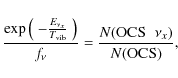
|
(1) |
where
| |
= | 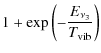
|
|
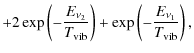
|
(2) |
which, for low
From the observed lines, we obtain
![]() K for OCS
K for OCS ![]() ,
and
,
and
![]() K for OCS
K for OCS ![]() .
These values are similar to the
averaged kinetic temperature we adopted for the hot core component (225 K).
A direct comparison of the derived
.
These values are similar to the
averaged kinetic temperature we adopted for the hot core component (225 K).
A direct comparison of the derived
![]() for OCS with the average
Tk assumed for the gas in the hot core is difficult. Vibrational
excitation is expected to depend strongly on temperature and density
gradients in that region. It is also difficult to ascertain if either IR dust
photons or molecular collisions dominate the vibrational excitation of OCS
given the lack of collisional rates for that
species. Nevertheless, assuming that
ro-vibrational collisional rates for OCS are similar to those
of SiO or SiS (Tobola et al. 2008),
for OCS with the average
Tk assumed for the gas in the hot core is difficult. Vibrational
excitation is expected to depend strongly on temperature and density
gradients in that region. It is also difficult to ascertain if either IR dust
photons or molecular collisions dominate the vibrational excitation of OCS
given the lack of collisional rates for that
species. Nevertheless, assuming that
ro-vibrational collisional rates for OCS are similar to those
of SiO or SiS (Tobola et al. 2008), ![]() (
(
![]() K
K
![]() cm3 s-1,
we find that, even for H2 densities as high as 109 cm-3,
the net collisional rate is well below the spontaneous de-excitation
rates from
cm3 s-1,
we find that, even for H2 densities as high as 109 cm-3,
the net collisional rate is well below the spontaneous de-excitation
rates from ![]() and
and ![]() to the ground state. Hence, the
population of these levels have to be mainly caused by IR photons
from the dust. That the OCS rotational lines are narrower
in vibrationally excited states than in
to the ground state. Hence, the
population of these levels have to be mainly caused by IR photons
from the dust. That the OCS rotational lines are narrower
in vibrationally excited states than in ![]() may indicate that this
IR pumping operates in a more compact region with a shallower velocity
gradient.
Higher angular resolution observations are necessary
to resolve any possible excitation gradient and temperature
profile in this component.
may indicate that this
IR pumping operates in a more compact region with a shallower velocity
gradient.
Higher angular resolution observations are necessary
to resolve any possible excitation gradient and temperature
profile in this component.
We also calculated
the vibrational temperature for the first vibrationally excited state of CS
(
![]() K). With the column density results
of the CS hot core component (
K). With the column density results
of the CS hot core component (
![]() cm-2) and
of CS
cm-2) and
of CS
![]() cm-2), we
obtain an upper limit to the vibrational temperature of
cm-2), we
obtain an upper limit to the vibrational temperature of ![]() 300 K, which agrees with the values obtained for vibrationally
excited OCS. However, in this case we could claim an inner and hotter emitting region for vibrationally excited CS.
300 K, which agrees with the values obtained for vibrationally
excited OCS. However, in this case we could claim an inner and hotter emitting region for vibrationally excited CS.
Nevertheless, since the vibrationally excited gas is not necessarily spatially coincident with the ground state gas, the derived vibrational temperatures have to be considered as lower limits.
Table 9: Column density ratios.
8 Discussion and conclusions
The power of spectral line surveys at different mm and sub-mm wavelengths to search for new molecular species and derive the physical and chemical structure of molecular sources has been demonstrated (Blake et al. 1987; Sutton et al. 1995; Cernicharo et al. 2000; Schilke et al. 2001; Pardo & Cernicharo 2007). The main and final goal of our line survey is to provide a consistent set of molecular abundances derived from a systematic analysis of the molecular rotational transitions. Our line survey allows us to obtain with unprecedented sensitivity and completeness the census of the identified and unidentified molecules in Orion KL. These kinds of studies are necessary to understand the chemical evolution of this archetypal star-forming region. Moreover, that many rotational transitions of the same molecule have been observed in different frequency ranges (the 3 mm window illustrates more clearly the extended ridge component, whereas the 1.3 mm one identifies the warmest gas at the hot core and along the compact ridge), provide strong observational constraints on the source structure, gas temperature, gas density, and molecular column densities.
8.1 Molecular abundances
Molecular abundances were derived using the H2 column density
calculated by means of the C18O column
density provided in Sect. 5.4,
assuming that CO is a robust tracer of
H2 and therefore their abundance ratio is roughly constant,
ranging from CO/H
![]() (for the ridge components) to
(for the ridge components) to
![]() (for the hot core and the plateau). In spite of
the large uncertainty in this calculation, we
include it as a more intuitive result for
the molecules described in the paper.
We obtained N(H
(for the hot core and the plateau). In spite of
the large uncertainty in this calculation, we
include it as a more intuitive result for
the molecules described in the paper.
We obtained N(H
![]() ,
,
![]() ,
,
![]() ,
and
,
and
![]() cm-2 for the extended
ridge, compact ridge, plateau, and hot core, respectively. In addition,
we assume that the
H2 column density spatially coincides with the emission from the
species considered.
Our estimated source average abundances for each Orion KL component
are summarized in
Table B.10 (only available online),
together with comparison values from other
authors (Sutton et al. 1995 and Persson et al. 2007).
The differences between the abundances shown in Table B.10
are mostly due to the different
H2 column density considered, to the assumed cloud component of the
molecular emission and discrepancies in
the sizes of these components.
cm-2 for the extended
ridge, compact ridge, plateau, and hot core, respectively. In addition,
we assume that the
H2 column density spatially coincides with the emission from the
species considered.
Our estimated source average abundances for each Orion KL component
are summarized in
Table B.10 (only available online),
together with comparison values from other
authors (Sutton et al. 1995 and Persson et al. 2007).
The differences between the abundances shown in Table B.10
are mostly due to the different
H2 column density considered, to the assumed cloud component of the
molecular emission and discrepancies in
the sizes of these components.
8.2 Column density ratios
To compare the chemistry of the different spectral cloud components related to sulfur-bearing carbon chains molecules, we derived the column density ratios showed in Table 9. This table also shows the ratios found in chemical models of hot cores, other results found in the literature for Orion, and other sources (the dark cloud TMC-1 and the hot core G327.3-0.6). We found good agreement between our ratios and those derived by Persson et al. (2007), both set of values corresponding to Orion KL. For the other molecular hot core, we noted a large difference in the ratio CO/CS. This discrepancy also occurs with the chemical models computed by Nomura & Millar (2004). We note that the chemical models cannot provide realistic values for the H2CO/H2CS column density ratio, as we have discussed in Sect. 5.3. TMC-1 exhibits ratios very different by those of hot cores, as expected from their different chemical and physical conditions.
We find N(C34S/OC34S
![]() ,
0.6, 0.2, and 0.2 in the
extended ridge, the compact ridge, the plateau, and the hot core,
respectively. The chemical models for hot cores
computed by Nomura & Millar (2004) infer that N(CS)/N(OCS) = 0.2 (at 104 years).
The N(CS)/N(CCS) abundance ratio
is 300, 1143, 1000, and 280 for the
extended ridge, the compact ridge, the plateau, and the hot core,
respectively. For the hot core, we also derive
N(CS)/N(C3S)
,
0.6, 0.2, and 0.2 in the
extended ridge, the compact ridge, the plateau, and the hot core,
respectively. The chemical models for hot cores
computed by Nomura & Millar (2004) infer that N(CS)/N(OCS) = 0.2 (at 104 years).
The N(CS)/N(CCS) abundance ratio
is 300, 1143, 1000, and 280 for the
extended ridge, the compact ridge, the plateau, and the hot core,
respectively. For the hot core, we also derive
N(CS)/N(C3S)
![]() .
Both CCS
and C3S have
not been studied in the chemical models available for hot cores. As expected,
these values are very different from those derived in the dark
cloud TMC-1 for which N(CS)/N(CCS)=2.2 and N(CS)/N(C3S)=7.8(Hirahara et al. 1992).
However, we obtain N(C2S)/N(C3S) = 2.5, very similar to the
3.4 value derived by Hirahara et al. (1992) in TMC-1 (cyanopolyyne peak) and
the value of
.
Both CCS
and C3S have
not been studied in the chemical models available for hot cores. As expected,
these values are very different from those derived in the dark
cloud TMC-1 for which N(CS)/N(CCS)=2.2 and N(CS)/N(C3S)=7.8(Hirahara et al. 1992).
However, we obtain N(C2S)/N(C3S) = 2.5, very similar to the
3.4 value derived by Hirahara et al. (1992) in TMC-1 (cyanopolyyne peak) and
the value of ![]() 3 found in the envelope of the C-rich star IRC+10216 by
Cernicharo et al. (1987a).
3 found in the envelope of the C-rich star IRC+10216 by
Cernicharo et al. (1987a).
This is a surprising result because CCS
is considered to be a typical molecule in cold dark clouds. Moreover, C3S
is found only in the hot core, which is indicative of an enhancement in the production
of CCS and C3S in the warm and dense gas. Although spectral confusion
is large when observing weak lines such as those of C3S, thanks to
our survey, we detected
17 lines. They cover from the J=14-13 (
![]() K
with
K
with
![]() km s-1)
up to J=47-46 (
km s-1)
up to J=47-46 (
![]() K with
K with
![]() km s-1),
thus, we are fully confident in its detection. In addition, the
observed velocities
correspond definitively to the hot core.
km s-1),
thus, we are fully confident in its detection. In addition, the
observed velocities
correspond definitively to the hot core.
Our results indicate that
C3S is efficiently formed in warm regions. That the
C2S/C3S abundance ratio is similar to that of dark clouds or
evolved stars may indicate that these species formed in the gas
phase. Gas phase chemical models predict C2S/C3S ![]() 2 and 0.3
in TMC-1 and IRC10216, respectively (Walsh et al. 2009; Cordiner & Millar 2009).
2 and 0.3
in TMC-1 and IRC10216, respectively (Walsh et al. 2009; Cordiner & Millar 2009).
8.3 Orion KL cloud structure
We have analyzed and discussed the emission
lines of the studied
molecules in terms of the four well-known Orion KL
cloud components (hot core, extended ridge, compact ridge, and
plateau).
However, low angular resolution
does not enable us to detect any possible
variation in the excitation temperature across the hot core and
the other Orion components. A more complex physical structure has
been observed with sensitive interferometers
(Beuther et al. 2005; Wright et al. 1996; Plambeck et al. 2009; Zapata et al. 2009a).
Further analysis of our survey indicates that at the position of IRc2, the
lines of both SiS and the SiO maser emission
show a velocity component at 15.5 km s-1, an additional cloud
component to those described above.
Owing to the high energies involved in some emission lines,
Schilke et al. (2001) and Comito et al. (2005) claimed that a hotter component exists
at the
hot core
![]() in their surveys at high frequency. In the
same way, we detected the emission of vibrationally excited OCS and
CS at the hot core LSR velocity.
In spite of the low angular resolution of our data, the amount
of molecules, the large number of
transitions, and the different vibrationally excited states found in
the survey permit us to derive realistic source-averaged physical
and chemical parameters.
in their surveys at high frequency. In the
same way, we detected the emission of vibrationally excited OCS and
CS at the hot core LSR velocity.
In spite of the low angular resolution of our data, the amount
of molecules, the large number of
transitions, and the different vibrationally excited states found in
the survey permit us to derive realistic source-averaged physical
and chemical parameters.
9 Summary
We have presented an IRAM 30-m line survey of Orion KL with the
highest sensitivity
achieved to date. Because of the wide frequency range covered and high data
quality, we intent to present the line survey in a series of papers
focused in different molecular families.
In this paper, we have presented the study of
the emission from OCS, its isotopologues, and its vibrationally
excited states (![]() and
and ![]() ), as well as HCS+, H2CS, CS, CCS, CCCS, and
different isotopic substitutions of them. The four well known
components of Orion (hot core, plateau, extended ridge and compact
ridge) contribute to the observed emission from
the main isotopologues of all these molecules except for C3S,
which we only detected in the hot core component.
), as well as HCS+, H2CS, CS, CCS, CCCS, and
different isotopic substitutions of them. The four well known
components of Orion (hot core, plateau, extended ridge and compact
ridge) contribute to the observed emission from
the main isotopologues of all these molecules except for C3S,
which we only detected in the hot core component.
Column densities have been calculated with radiative transfer codes based on either the LVG or the LTE approximations, taking into account the physical structure of the source. Results are provided as source-averaged column densities. In this way, our column density for OCS are between 4 to 10 times higher than the beam-averaged ones provided in previous surveys. Our column density derived for the hot core component compares well with the values obtained by Sutton et al. (1995) and Comito et al. (2005). Among those studied in this paper in all the cloud components, OCS appears as the most abundant species.
We have also reported on the first detection in space of OCS
in the vibrationally excited states ![]() and
and ![]() .
This
emission arises mostly from the hot core component.
The resulting
vibrational temperature (
.
This
emission arises mostly from the hot core component.
The resulting
vibrational temperature (![]() 210 K) is similar to the kinetic
temperature of this component (
210 K) is similar to the kinetic
temperature of this component (![]() 225 K).
225 K).
For HCS+, we have to significantly reduce the contribution of the extended ridge component to reproduce all lines arising in our survey. The derived N(HCS+)/N(HCO+) ratio is in agreement with the observed N(CS)/N(CO) ratio in terms of chemical equilibrium.
The statistical value of 3 for the ortho-to-para ratio has been
confirmed by the study of the emission lines of H2CS and its
isotopologues. We have derived an abundance ratio of H2CS/HDCS ![]() 20.
20.
For CS, we have analyzed the emission of 7 distinct isotopologues
and the vibrational state v = 1.
The lines of the main isotopologue
are optically thick and therefore we have derived the column density by means
of the isotopologues (assuming the derived isotopic abundances from
this work). Our results
are in agreement with those of Sutton et al. (1995) and Comito et al. (2005).
The vibrational temperature
calculated for CS v = 1 (tentative detection) is less than 300 K,
in agreement with those values obtained for OCS ![]() and
and ![]() .
However, this result may indicate that there is an inner, hotter region of
emission from vibrationally excited CS that is difficult to resolve with our low
angular resolution observations.
.
However, this result may indicate that there is an inner, hotter region of
emission from vibrationally excited CS that is difficult to resolve with our low
angular resolution observations.
Since the intensity of the C2S and C3S lines is already weak,
we could not detect either their isotopologues or their vibrationally excited
states.
We derived column densities of
![]() cm-2 and
cm-2 and
![]() cm-2, respectively in the hot
core component from the detected lines. We have detected C3S for
the first time in warm regions.
Finally, we have derived upper limits to the column density of
non-detected molecules (-CS bearing species), obtaining the maximum
value for thioketene N(H2CCS
cm-2, respectively in the hot
core component from the detected lines. We have detected C3S for
the first time in warm regions.
Finally, we have derived upper limits to the column density of
non-detected molecules (-CS bearing species), obtaining the maximum
value for thioketene N(H2CCS
![]() cm-2.
cm-2.
From the column density results, we have derived several abundance
ratios that permit us to provide the following average isotopic abundances:
12C/13C = ![]() ,
32S/34S =
,
32S/34S = ![]() ,
32S/33S =
,
32S/33S = ![]() ,
and 16O/18O =
,
and 16O/18O =
![]() (all of them in agreement with
the solar isotopic abundances, see Sect. 6 and
Table B.9, only available online).
(all of them in agreement with
the solar isotopic abundances, see Sect. 6 and
Table B.9, only available online).
Orion KL has been observed and described by a large number of authors. Single-dish observations cannot provide details about the complex physical structure and true spatial distribution that interferometric observations do reveal. It is not possible, for example, to track the variation in the excitation temperature in the hot core region that appear to exist according to the vibrational temperature derived from vibrationally excited CS. The need from a large contribution from the extended ridge component before OCS can reproduce the line profiles towards the hot core, relative to the contribution of the ambient molecular cloud (far away IRc2), implies that at the border between the hot core and the extended ridge, there is a physical structure with density and temperature gradients that the single-dish telescopes cannot resolve. Higher angular resolution observations are necessary to describe this source in detail and to reveal its physical structure. Interferometric instruments such as Plateau de Bure, SMA, or the future ALMA are necessary to avoid spectral confusion related to varying physical conditions inside large beams and to resolve the source structure. Nevertheless, the 30 m line survey of Orion will provide a consistent determination of column densities of all species with emission above 0.1 K.
AcknowledgementsWe thank the Spanish MEC for funding support through grants AYA2003-2785, AYA2006-14876, AYA2009-07304, ESP2004-665 and AP2003-4619 (M. A.), Consolider project CSD2009-00038 the DGU of the Madrid Community government for support under IV-PRICIT project S-0505/ESP-0237 (ASTROCAM). Javier R. Goicoechea was supported by a Ramón y Cajal research contract from the Spanish MICINN and co-financed by the European Social Fund.
References
- Ahrens, V., & Winnewisser, G. 1998, Z. Naturforsch, 54a, 131 [Google Scholar]
- Anders, E., & Grevesse, N. 1989, GeCoA, 53, 197 [Google Scholar]
- Bell, M. B., Avery, L. W., & Feldman, P. A. 1993, ApJ, 417, L40 [Google Scholar]
- Beuther, H., Zhang, Q., Greenhill, L. J., et al. 2004, ApJ, 616, L31 [Google Scholar]
- Beuther, H., Zhang, Q., Greenhill, L. J., et al. 2005, ApJ, 632, 355 [NASA ADS] [CrossRef] [Google Scholar]
- Beuther, H., & Nissen, H. D. 2008, ApJ, 679, L121 [NASA ADS] [CrossRef] [Google Scholar]
- Blake, G. A., Sutton, E. C., Masson, C. R., & Philips, T. H. 1986, ApJS, 60, 357 [NASA ADS] [CrossRef] [Google Scholar]
- Blake, G. A., Sutton, E. C., Masson, C. R., & Philips, T. H. 1987, ApJ, 315, 621 [NASA ADS] [CrossRef] [Google Scholar]
- Blake, G. A., Mundy, L. G., Carlstrom, J. E., et al. 1996, ApJ, 472, L49 [NASA ADS] [CrossRef] [Google Scholar]
- Botschwina, P., & Sebald, P. 1985, J. Mol. Spectrosc., 110, 1 [NASA ADS] [CrossRef] [Google Scholar]
- Brown, P. D., Charnley, S. B., & Millar, T. J. 1988, MNRAS, 231, 409 [NASA ADS] [CrossRef] [Google Scholar]
- Burenin, A. V., Val'Dov, A. N., Karyakin, E. N., Krupnov, A. F., & Shapin, S. M. 1981, JMoSp, 87, 312B [Google Scholar]
- Burenin, A. V., Karyakin, E. N., Krupnov, A. F., Shapin, S. M., & Val'Dov, A. N. 1981, JMoSp, 85, 1B [NASA ADS] [Google Scholar]
- Carvajal, M., Margulès, L., Tercero, B., et al. 2009, A&A, 500, 1109 [NASA ADS] [CrossRef] [EDP Sciences] [Google Scholar]
- Cernicharo, 1985, Internal IRAM report (Granada: IRAM) [Google Scholar]
- Cernicharo, J., & Guèlin, M. 1987, A&A, 176, 299 [NASA ADS] [Google Scholar]
- Cernicharo, J., Guèlin, M., Hein, H., & Kahane, C. 1987a, A&A, 181, L9 [NASA ADS] [Google Scholar]
- Cernicharo, J., Guèlin, M., & Kahane, C. 2000, A&A, 142, 181 [NASA ADS] [Google Scholar]
- Charnley, S. B. 1997, ApJ, 481, 396 [NASA ADS] [CrossRef] [Google Scholar]
- Comito, C., Schilke, P., Philips, T. G., et al. 2005, ApJS, 165, 127 [NASA ADS] [CrossRef] [Google Scholar]
- Cordiner, M. A., & Millar, T. J. 2009, ApJ, 697, 68 [NASA ADS] [CrossRef] [Google Scholar]
- Corey, G. C. 1984, JChPh, 81, 2678 [Google Scholar]
- Corey, G. C. 1984, JChPh, 81, 2678 [Google Scholar]
- Demyk, K., Mäder, H., Tercero, B., et al. 2007, A&A, 466, 255 [NASA ADS] [CrossRef] [EDP Sciences] [Google Scholar]
- de Vicente, P., Martín-Pintado, J., Neri, R., & Rodríguez-Franco, A. 2002, ApJ, 574, L163 [NASA ADS] [CrossRef] [Google Scholar]
- Dougados, C., Lena, P., Ridgway, S. T., Christou, J. C. & Probst, R. G. 1993 ApJ, 406, 112 [Google Scholar]
- Evans, II, N. J., Lacy, J. H., & Carr, J. S. 1991 ApJ, 383, 674 [Google Scholar]
- Fabricant, B., Krieger, D., & Muenter, J. S. 1977, J. Chem. Phys., 67, 1576 [NASA ADS] [CrossRef] [Google Scholar]
- Frerking, M. A., Linke, R. A., Thaddeus, P. 1979, ApJ, 234, 143 [Google Scholar]
- Friedel, D. N., Snyder, L. E., Remijan, A. J., & Turner, B. E. 2005, ApJ, 632, L95 [NASA ADS] [CrossRef] [Google Scholar]
- Fuente, A., Cernicharo, J., Barcia, A., & Gómez-González, J. 1990, A&A, 231, 151 [NASA ADS] [Google Scholar]
- Gardner, F. F., Hölglund, B., Shukre, C., Stark, A. A., & Wilson, T. L. 1985, A&A, 146, 303 [NASA ADS] [Google Scholar]
- Genzel, R., & Stutzki, J. 1989, ARA&A, 27, 41 [NASA ADS] [CrossRef] [Google Scholar]
- Georgiou, K., Kroto, H. W., & Landsberg, B. M. 1979, JMoSp., 77, 365 [NASA ADS] [Google Scholar]
- Gezari, D. Y., Backman, D. E., & Werner, M. W. 1998 ApJ, 509, 283 [Google Scholar]
- Gibb, E., Nummelin, A., Irvine, W. M., Whittet, D. C. B., & Bergman, P. 2000, ApJ, 545, 309 [NASA ADS] [CrossRef] [PubMed] [Google Scholar]
- Goddi, C., Greenhill, L. J., Humphreys, E. M. L., et al. 2009a, ApJ, 691, 1254 [NASA ADS] [CrossRef] [Google Scholar]
- Goddi, C., Greenhill, L. J., Chandler, C. J., et al. 2009b, ApJ, 698, 1165 [NASA ADS] [CrossRef] [Google Scholar]
- Goldflam, R., Kouri, D. J., & Green, S. 1977, J. Chem. Phys., 67, 4149 [NASA ADS] [CrossRef] [Google Scholar]
- Goldsmith, P. F., & Linke, R. A. 1981, ApJ, 245, 482 [NASA ADS] [CrossRef] [Google Scholar]
- Golubiatnikov, G. Yu., Lapinov, A. V., Guarnieri, A., & Knöchel, R. 2005, JMoSp, 234, 190 [Google Scholar]
- Gómez, L., Rodríguez, L. F., Loinard, L., et al. 2005, ApJ, 635, 1166 [NASA ADS] [CrossRef] [Google Scholar]
- González-Alfonso, E., & Cernicharo, J. 1993, A&A, 279, 506 [NASA ADS] [Google Scholar]
- Gottlieb, C. A., Myers, P. C., & Thaddeus, P. 2003, ApJ, 588, 655 [NASA ADS] [CrossRef] [Google Scholar]
- Greaves, J. S., & White, G. J. 1991, A&ASS, 91, 237 [NASA ADS] [Google Scholar]
- Green, S., & Chapman, S. 1978, ApJS, 37, 169 [NASA ADS] [CrossRef] [Google Scholar]
- Greenhill, L. J., Gezari, D. Y., Danchi, et al. 2004, ApJ, 605, L57 [NASA ADS] [CrossRef] [Google Scholar]
- Hasegawa, T., Kaifu, N., Inatani, J., et al. 1984, ApJ, 283, 117 [NASA ADS] [CrossRef] [Google Scholar]
- Hirahara, Y., Suzuki, H., Yamamoto, S., et al. 1992, ApJ, 394, 539 [NASA ADS] [CrossRef] [Google Scholar]
- Jewell, P. R., Hollis, J. M., Lovas, F. J., & Snyder, L. E. 1989, ApJS, 70, 833 [NASA ADS] [CrossRef] [Google Scholar]
- Johansson, L. E. B., Andersson, C., Elldér, J., et al. 1984, A&A, 130, 227 [NASA ADS] [PubMed] [Google Scholar]
- Johnstone, D., Boonman, A. M. S., & van Dishoeck, E. F. 2003, A&A, 412, 157 [NASA ADS] [CrossRef] [EDP Sciences] [Google Scholar]
- Kaifu, N., Suzuki, H., Ohishi, M., et al. 1987, ApJ, 317, L111 [NASA ADS] [CrossRef] [Google Scholar]
- Kim, E., & Yamamoto, S. 2003, JMoSp, 219, 296 [Google Scholar]
- Lee, C. W., Cho, S. H., & Lee, S. M. 2001, ApJ, 551, 333 [NASA ADS] [CrossRef] [Google Scholar]
- Lee, C. W., & Cho, S. H. 2002, J. Korea Astron. Soc., 35, 187 [Google Scholar]
- Lee, S. 1997, Chem. Phys. Lett., 268, 69 [NASA ADS] [CrossRef] [Google Scholar]
- Lerate, M. R., Barlow, M. J., Swinyard, B. M., et al. 2006, MNRAS, 370, 597 [NASA ADS] [CrossRef] [Google Scholar]
- Lique, F., & Spielfiedel, A. 2007, A&A, 462, 1179 [NASA ADS] [CrossRef] [EDP Sciences] [Google Scholar]
- Liu, S.-Y., Girart, J. M., Remijan, A., & Snyder, L. E. 2002, ApJ, 576, 255 [NASA ADS] [CrossRef] [Google Scholar]
- Maeda, A., Medvedev, I. R., Winnewisser, M., et al. 2008, ApJS, 176, 543 [NASA ADS] [CrossRef] [Google Scholar]
- Marcelino, N., Cernicharo, J., Roueff, E., Gerin, M., & Mauersberger, R. 2005, ApJ, 620, 308 [NASA ADS] [CrossRef] [Google Scholar]
- Marcelino, N., Cernicharo, J., Tercero, B., & Roueff, E. 2009, ApJ, 690, 27 [Google Scholar]
- Margulès, L., Lewen, F., Winnewisser, G., Botschwina, P., & Müller, H. S. P. 2003, Phys. Chem. Chem. Phys., 5, 2770 [CrossRef] [Google Scholar]
- Margulès, L., Motiyenko, R., Demyk, K., et al. 2009, A&A, 493, 565 [NASA ADS] [CrossRef] [EDP Sciences] [Google Scholar]
- Margulès, L., Huet, T. R., Demaison, J., et al. 2010, ApJ, 714, 1120 [NASA ADS] [CrossRef] [Google Scholar]
- Matthews, H. E., MacLeod, J. M., Broten, N. W., Madden, S. C., & Friberg, P. 1987, ApJ, 315, 646 [NASA ADS] [CrossRef] [PubMed] [Google Scholar]
- McNaughton, D. 1996, JMoSp., 175, 377 [NASA ADS] [Google Scholar]
- Menten, K. M., & Reid, M. J. 1995, ApJ, 445, L157 [NASA ADS] [CrossRef] [Google Scholar]
- Menten, K. M., Reid, M. J., Forbrich, J., & Brunthaler, A. 2007, A&A, 474, 515 [NASA ADS] [CrossRef] [EDP Sciences] [Google Scholar]
- Minh, Y. C., Irvine, W. M., & Brewer, M. K. 1991, A&A, 244, 181 [NASA ADS] [PubMed] [Google Scholar]
- Minowa, H., Satake, M., Hirota, T., et al. 1997, ApJ, 491, L63 [NASA ADS] [CrossRef] [Google Scholar]
- Monteiro, T. 1984, MNRAS, 210, 1 [NASA ADS] [Google Scholar]
- Morino, I., Yamada, K. M. T., & Maki, A. G. 2000, JMoSp, 200, 145 [Google Scholar]
- Morris, M., Palmer, P., & Zuckerman, B. 1980, ApJ, 237, 1 [NASA ADS] [CrossRef] [Google Scholar]
- Müller, H. S. P., Thorwirth, S., Roth, D. A., & Winnewisser, G. 2001, A&A, 370, L49 [NASA ADS] [CrossRef] [EDP Sciences] [Google Scholar]
- Müller, H. S. P., Schlöder, F., Stutzki, J., & Winnewisser, G. 2005, J. Mol. Struct., 742, 215 [NASA ADS] [CrossRef] [Google Scholar]
- Murata, Y., Kawabe, R., Ishiguro, M., Hasegawa, T., & Hayashi, M. 1991, IAUS, 147, 357 [NASA ADS] [Google Scholar]
- Niedenhoff, M. 1995, JMoSp., 169, 224 [Google Scholar]
- Nomura, H., & Millar, T. J. 2004, A&A, 414, 409 [NASA ADS] [CrossRef] [EDP Sciences] [MathSciNet] [Google Scholar]
- Ohshima, Y., & Endo, Y. 1996, Chem. Phys. Lett., 256, 635 [NASA ADS] [CrossRef] [Google Scholar]
- Olofsson, A. O. H., Persson, C. M., Koning, N., et al. 2007, A&A, 476, 791 [NASA ADS] [CrossRef] [EDP Sciences] [Google Scholar]
- Pardo, J. R., Cernicharo, J., & Serabyn, E. 2001, IEEE Tras. Antennas and Propagation, 49, 12 [Google Scholar]
- Pardo, J. R., Cernicharo, J., Herpin, F., et al. 2001, ApJ, 562, 799 [NASA ADS] [CrossRef] [Google Scholar]
- Pardo, J. R., & Cernicharo, J. 2007, ApJ, 654, 978 [NASA ADS] [CrossRef] [Google Scholar]
- Persson, C. M., Olofsson, A. O. H., Koning, N., et al. 2007, A&A, 476, 807 [NASA ADS] [CrossRef] [EDP Sciences] [Google Scholar]
- Plambeck, R. L., & Wright, M. C. H. 1988, ApJ, 330, L61 [NASA ADS] [CrossRef] [Google Scholar]
- Plambeck, R. L., Wright, M. C. H., Friedel, D. N., et al. 2009, ApJ, 704, L25 [NASA ADS] [CrossRef] [Google Scholar]
- Roberts, H., Herbst, E., & Millar, T. J. 2002, MNRAS, 336, 283 [NASA ADS] [CrossRef] [Google Scholar]
- Rodgers, S. D., & Millar, T. J. 1996, MNRAS, 280, 1046 [NASA ADS] [CrossRef] [Google Scholar]
- Rodríguez, L. F., Zapata, L. A., & Ho, P. T. P. 2009, ApJ, 692, 162 [NASA ADS] [CrossRef] [Google Scholar]
- Savage, C., Apponi, A. J., Ziurys, L. M., & Wyckoff, S. 2002, ApJ, 578, 211 [NASA ADS] [CrossRef] [Google Scholar]
- Schilke, P., Walmsley, C. M., Pineau Des Forets, G., et al. 1992, A&A, 256, 595 [NASA ADS] [Google Scholar]
- Schilke, P., Groesbeck, T. D., Blake, G. A., & Philips, T. G. 1997, ApJS, 108, 301 [NASA ADS] [CrossRef] [Google Scholar]
- Schilke, P., Benford, C. J., Hunter, T. R., Lis, D. C., & Philips, T. G. 2001, ApJS, 132, 281 [NASA ADS] [CrossRef] [Google Scholar]
- Serabyn, E., & Weisstein, E. W. 1995, ApJ, 451, 238 [NASA ADS] [CrossRef] [Google Scholar]
- Shuping, R. Y., Morris, M., & Bally, J. 2004, AJ, 128, 363 [NASA ADS] [CrossRef] [Google Scholar]
- Sobolev, V. V. 1958, en Theorical Astrophysics, ed. Ambartsumyan, Pergamon Press Ltd. London Cap. 29 [Google Scholar]
- Sobolev, V. V. 1960, en Moving Envelopes of Stars (Hardvard University Press) [Google Scholar]
- Suenram, R. D., & Lovas, F. J. 1994, ApJ, 429, L89 [NASA ADS] [CrossRef] [Google Scholar]
- Sutton, E. C., Blake, G. A., Masson, C. R., & Philips, T. G. 1985, ApJS, 58, 341 [NASA ADS] [CrossRef] [Google Scholar]
- Sutton, E. C., Blake, G. A., Genzel, R., Masson, C. R., & Philips, T. G. 1986, ApJS, 311, 921 [NASA ADS] [CrossRef] [Google Scholar]
- Sutton, E. C., Peng, R., Danchi, W. C., et al. 1995, ApJS, 97, 455 [NASA ADS] [CrossRef] [Google Scholar]
- Szalanski, L. B., Gerry, M. C. L., Winnewisser, G., Yamada, K. M. T., & Winnewisser, M. 1978, Can. J. Phys., 56, 1297 [NASA ADS] [Google Scholar]
- Tanaka, K., Tanaka, T., & Suzuki, I. 1985, JChPhys., 82, 2835 [Google Scholar]
- Tobola, R., Lique, F., Klos, J., & Chalasinski, G. 2008, JPhB, 41, 155702 [NASA ADS] [Google Scholar]
- Turner, B. E. 1989, ApJS, 70, 539 [NASA ADS] [CrossRef] [Google Scholar]
- Turner, B. E. 1991, ApJS, 76, 617 [NASA ADS] [CrossRef] [Google Scholar]
- Walsh, C., Harada, N., Herbst, E., & Millar, T. J. 2009, ApJ, 700, 752 [NASA ADS] [CrossRef] [Google Scholar]
- Wheeler, S. E., Yamaguchi, Y., & Schaefer, H. F. 2006, JChPh, 124, 044322 [Google Scholar]
- White, G. J., Monteiro, T. S., Richardson, K. J., Griffin, M. J., & Rainey, R. 1986, A&A, 162, 253 [NASA ADS] [Google Scholar]
- White, G. J., Araki, M., Greaves, J. S., Ohishi, M., & Higginbottom, N. S. 2003, A&A, 407, 598 [Google Scholar]
- Winnewisser, G., & Cook, R. L. 1968, J. Mol. Spect., 28, 266 [CrossRef] [Google Scholar]
- Winnewisser, M., & Schäfer, E. 1980, Zeitschrift Naturforschung Teil A, 35, 483 [NASA ADS] [Google Scholar]
- Winnewisser, M., Lichau, H., & Wolf, F. 2000, J. Mol. Spect., 202, 155 [Google Scholar]
- Wright, M. C. H., Plambeck, R. L., & Wilner, D. J. 1996, ApJ, 469, 216 [NASA ADS] [CrossRef] [Google Scholar]
- Wyckoff, S., Kleine, M., Peterson, B. A., Wehinger, P. A., & Ziurys, L. M. 2000, ApJ, 535, 991 [NASA ADS] [CrossRef] [Google Scholar]
- Yamamoto, S., Saito, S., Kawaguchi, K., et al. 1987, ApJ, 317, L119 [NASA ADS] [CrossRef] [Google Scholar]
- Yamamoto, S., Saito, S., Kawaguchi, K., et al. 1990, ApJ, 361, 318 [NASA ADS] [CrossRef] [Google Scholar]
- Zapata, L. A., Menten, K., Reid, M., & Beuther, H. 2009a, ApJ, 691, 332 [NASA ADS] [CrossRef] [Google Scholar]
- Zapata, L. A., Schmid-Burgk, J., Ho, P. T. P., Rodríguez, L. F., & Menten, K. M. 2009b, ApJ, 704, L45 [NASA ADS] [CrossRef] [Google Scholar]
- Zeng, Q., & Pei, C. C. 1995, Ap&SS, 229, 301 [NASA ADS] [CrossRef] [Google Scholar]
- Ziurys, L. M., & McGonagle, D. 1993, ApJS, 89, 155 [NASA ADS] [CrossRef] [Google Scholar]
Online Material
Appendix A: Online Figures
![\begin{figure}
\par\includegraphics[width=14cm,clip]{13501fgA1n.eps}
\end{figure}](/articles/aa/full_html/2010/09/aa13501-09/img193.png)
|
Figure A.1:
Observed lines (offseted histogram) and model
(thin curves) of O13CS, 18OCS, O13C34S,
17OCS, and OC36S. A
|
| Open with DEXTER | |
![\begin{figure}
\par\includegraphics[width=14cm,clip]{13501fgA2n.eps}
\end{figure}](/articles/aa/full_html/2010/09/aa13501-09/img194.png)
|
Figure A.2: Left panelshows the OCS J = 18-17 line at different positions. The right panel map shows the total integrated intensity of this transition; the interval of contours is 10 K km s-1, and the minimum contour is 40 K km s-1. |
| Open with DEXTER | |
![\begin{figure}
\par\includegraphics[width=6cm,clip]{13501fgA3.eps}
\end{figure}](/articles/aa/full_html/2010/09/aa13501-09/img195.png)
|
Figure A.3:
Observed lines (histogram) and model (thin
curves) of HCS+. A
|
| Open with DEXTER | |
![\begin{figure}
\par\includegraphics[width=14cm,clip]{13501fgA4.eps}
\end{figure}](/articles/aa/full_html/2010/09/aa13501-09/img196.png)
|
Figure A.4:
Observed lines (histogram) and model (thin
curves) of H2CS. A
|
| Open with DEXTER | |
![\begin{figure}
\par\includegraphics[width=14cm,clip]{13501fgA5.eps}
\end{figure}](/articles/aa/full_html/2010/09/aa13501-09/img197.png)
|
Figure A.5:
Observed lines (histogram) and model (thin
curves) of H2C34S. A
|
| Open with DEXTER | |
![\begin{figure}
\par\includegraphics[width=14cm,clip]{13501fgA6.eps}
\end{figure}](/articles/aa/full_html/2010/09/aa13501-09/img198.png)
|
Figure A.6:
H213CS observed (offseted histogram) and modeled
(continuum curves) lines. A
|
| Open with DEXTER | |
![\begin{figure}
\par\includegraphics[width=14cm,clip]{13501fgA7.eps}
\end{figure}](/articles/aa/full_html/2010/09/aa13501-09/img199.png)
|
Figure A.7:
HDCS observed (histogram) and modeled (thin
curves) lines. A
|
| Open with DEXTER | |
![\begin{figure}
\par\includegraphics[width=14.5cm,clip]{13501fgA8.eps}
\end{figure}](/articles/aa/full_html/2010/09/aa13501-09/img200.png)
|
Figure A.8:
Observed lines (offseted histogram) and modeled (thin
curves) of CS, CS isotopologues, and CS
|
| Open with DEXTER | |
Appendix B: Online Tables
Table B.1: OCS isotopologues and OCS vibrationally excited velocity components.
Table B.2: HCS+ Observed line parameters.
Table B.3: H2CS observed line parameters.
Table B.4: H2CS and its isotopologues velocity components.
Table B.5: CS observed line parameters.
Table B.6: CS and CS isotopologues velocities.
Table B.7: CCS observed lines parameters.
Table B.8: CCCS observed lines parameters.
Table B.9: Isotopologue ratios.
Table B.10: Molecular abundances.
Footnotes
- ... chains
- Appendices A and B are only available in electronic form at http://www.aanda.org
- ...
software
- http://www.iram.fr/IRAMFR/GILDAS
- ...
Catalog
- Müller et al. (2001), Müller et al. (2005) http://www.astro.uni-koeln.de/site/vorhersagen/.
All Tables
Table 1:
![]() and HPBW along the covered frequency range.
and HPBW along the covered frequency range.
Table 2: The assumed Orion KL spectral components.
Table 3: OCS observed line parameters.
Table 4: OCS velocity components from Gaussian fits.
Table 5: Column densities - OCS.
Table 6: Column densities - H2CS.
Table 7: Ortho/Para ratios - H2CS.
Table 8: Column densities of CS, CS isotopologues, and CS vibrationally excited.
Table 9: Column density ratios.
Table B.1: OCS isotopologues and OCS vibrationally excited velocity components.
Table B.2: HCS+ Observed line parameters.
Table B.3: H2CS observed line parameters.
Table B.4: H2CS and its isotopologues velocity components.
Table B.5: CS observed line parameters.
Table B.6: CS and CS isotopologues velocities.
Table B.7: CCS observed lines parameters.
Table B.8: CCCS observed lines parameters.
Table B.9: Isotopologue ratios.
Table B.10: Molecular abundances.
All Figures
|
|
Figure 1: The top panel shows two superimposed spectra corresponding to different frequency settings (112 500 and 112 520 MHz). The 40 MHz displaced line is the 115.5 GHz CO line in the image side band. The bottom panel shows the final spectrum resulting from our procedure to eliminate the image side band (see text, Sect. 2). We are confident that all lines above 0.05 K have frequencies correctly assigned. |
| Open with DEXTER | |
| In the text | |
|
|
Figure 2:
Molecular line survey of Orion KL at 3 mm. The top panel shows the total intensity scale; the middle and the bottom panels show a zoom of the total intensity. A
|
| Open with DEXTER | |
| In the text | |
|
|
Figure 3: Example of Orion's KL survey at 3 mm with 1 GHz bandwidth. The top panel shows the total intensity scale; the middle and the bottom panels show a zoom of the total intensity. Detected molecules are marked with labels and some unidentified features are marked as U. |
| Open with DEXTER | |
| In the text | |
|
|
Figure 4: Molecular line survey of Orion KL at 2 mm presented similarly to Fig. 2. |
| Open with DEXTER | |
| In the text | |
|
|
Figure 5: Example of Orion's KL survey at 2 mm with 1 GHz bandwidth. The top panel shows the total intensity scale; the middle and the bottom panels show a zoom of the total intensity. Detected molecules are marked with labels and some unidentified lines are marked as U. |
| Open with DEXTER | |
| In the text | |
|
|
Figure 6: Molecular line survey of Orion KL at 1.3 mm presented similarly to Fig. 2. |
| Open with DEXTER | |
| In the text | |
|
|
Figure 7: Example of the Orion KL survey at 1.3 mm with 1 GHz bandwidth. The top panel shows the total intensity scale; the middle and the bottom panels show a zoom of the total intensity. Detected molecules are labeled and some unidentified lines are marked as U. |
| Open with DEXTER | |
| In the text | |
|
|
Figure 8:
Observed (offseted histogram) and model
(thin curves) OCS, OC34S and OC33S lines.
A
|
| Open with DEXTER | |
| In the text | |
|
|
Figure 9:
Observed lines (offseted histogram) and model (thin
curves) of OCS |
| Open with DEXTER | |
| In the text | |
|
|
Figure 10: OCS J = 18-17 integrated line intensity maps at different velocity ranges (indicated at the top of each panel). The integrated intensity of the maps has been multiplied by a scale factor (indicated in the panels) to maintain the same color dynamics for all maps. The interval of contours is 10 K km s-1, the minimum contour is 30 K km s-1 for the maps with velocities between -1 and 11 km s-1 and 50 K km s-1 for the rest of the panels. |
| Open with DEXTER | |
| In the text | |
|
|
Figure 11:
Some lines of OCS, OC34S
and O13CS observed at different positions which correspond
with different components of Orion KL. A
|
| Open with DEXTER | |
| In the text | |
|
|
Figure 12:
Observed lines (offseted histogram) and model (thin
curves) of CCS. A
|
| Open with DEXTER | |
| In the text | |
|
|
Figure 13:
Observed lines (offseted histogram) and model (thin
curves) of C3S. A
|
| Open with DEXTER | |
| In the text | |
|
|
Figure A.1:
Observed lines (offseted histogram) and model
(thin curves) of O13CS, 18OCS, O13C34S,
17OCS, and OC36S. A
|
| Open with DEXTER | |
| In the text | |
|
|
Figure A.2: Left panelshows the OCS J = 18-17 line at different positions. The right panel map shows the total integrated intensity of this transition; the interval of contours is 10 K km s-1, and the minimum contour is 40 K km s-1. |
| Open with DEXTER | |
| In the text | |
|
|
Figure A.3:
Observed lines (histogram) and model (thin
curves) of HCS+. A
|
| Open with DEXTER | |
| In the text | |
|
|
Figure A.4:
Observed lines (histogram) and model (thin
curves) of H2CS. A
|
| Open with DEXTER | |
| In the text | |
|
|
Figure A.5:
Observed lines (histogram) and model (thin
curves) of H2C34S. A
|
| Open with DEXTER | |
| In the text | |
|
|
Figure A.6:
H213CS observed (offseted histogram) and modeled
(continuum curves) lines. A
|
| Open with DEXTER | |
| In the text | |
|
|
Figure A.7:
HDCS observed (histogram) and modeled (thin
curves) lines. A
|
| Open with DEXTER | |
| In the text | |
|
|
Figure A.8:
Observed lines (offseted histogram) and modeled (thin
curves) of CS, CS isotopologues, and CS
|
| Open with DEXTER | |
| In the text | |
Copyright ESO 2010
Current usage metrics show cumulative count of Article Views (full-text article views including HTML views, PDF and ePub downloads, according to the available data) and Abstracts Views on Vision4Press platform.
Data correspond to usage on the plateform after 2015. The current usage metrics is available 48-96 hours after online publication and is updated daily on week days.
Initial download of the metrics may take a while.