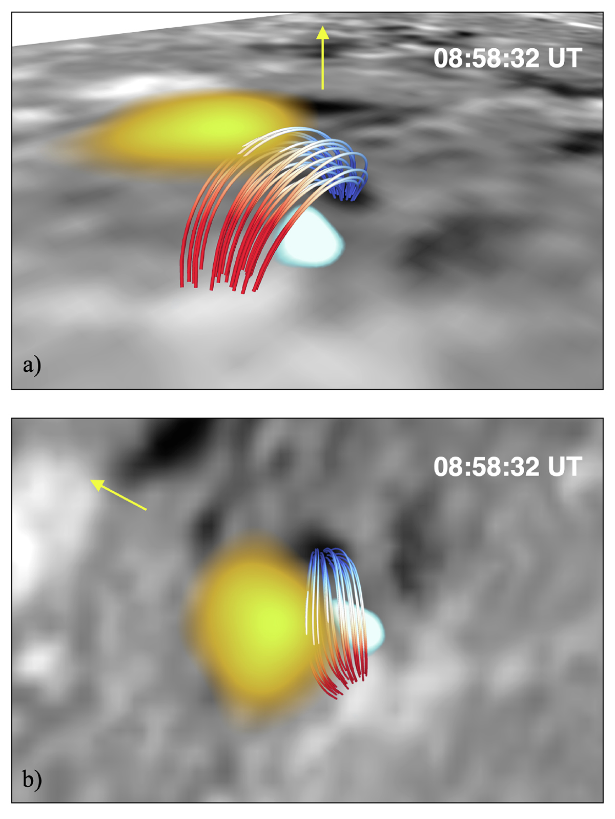
Fig. 6.
Download original image
Magnetic topology for a dipole configuration showing the co-spatial and co-temporal QSEB and UV brightening in Region 1. Panel (a) presents a 3D view with the north limb pointing up, the QSEB close to the photosphere, and the UV brightening at the top of the loops, slightly offset towards the north limb. Like in Fig. 4, the grey-scale image in the bottom is the BLOS map, and the higher image is the Hβ wing image with the QSEB in light blue and white shades. In this (and subsequent) 3D visualisation(s), the UV brightening in SJI 1400 is shown as a yellow patch. Panel (b) shows a top view of the loops, QSEB, and UV brightening. The yellow arrow shows the direction towards the limb.
Current usage metrics show cumulative count of Article Views (full-text article views including HTML views, PDF and ePub downloads, according to the available data) and Abstracts Views on Vision4Press platform.
Data correspond to usage on the plateform after 2015. The current usage metrics is available 48-96 hours after online publication and is updated daily on week days.
Initial download of the metrics may take a while.