Fig. 3.
Download original image
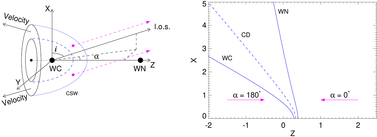
Physical picture of CSWs in massive banaries. Left panel: Schematic presentation of the CSW region in massive WC+WN binary. The label CSW marks the wind interaction region, which is a 3D structure with its axis of symmetry Z. The axes X and Y complete the Cartesian coordinate system. The two angles i (orbital inclination) and α (azimuthal angle) define the orientation in space of the line of sight (l.o.s.) towards the observer. The label ‘Velocity’ denotes the general direction of the shocked plasma flow. The two dashed-line arrows illustrate that emission from a parcel of gas in the CSW region is subject to different wind absorption, depending on the orientation (i, α) of the l.o.s. towards the observer and the rotational angle around the axis of symmetry (Z). Right panel: CSW region derived from the 2D hydrodynamic simulations for the adopted values of the stellar-wind parameters in Apep Plume which give a wind-momentum rate ratio of the stellar winds of Λ = 4.86. The x- and z-axes are in units of the binary separation. The WC and WN components are located at (x, z) coordinates (0, 0) and (0, 1), respectively. The solid lines mark the shock fronts and the dashed line marks the contact discontinuity. The half opening angle of the WC shock (WC), contact discontinuity (CD), and the WN shock (WN) ‘cones’ is ∼47°, ∼64°, and ∼84°, respectively.
Current usage metrics show cumulative count of Article Views (full-text article views including HTML views, PDF and ePub downloads, according to the available data) and Abstracts Views on Vision4Press platform.
Data correspond to usage on the plateform after 2015. The current usage metrics is available 48-96 hours after online publication and is updated daily on week days.
Initial download of the metrics may take a while.