| Issue |
A&A
Volume 682, February 2024
|
|
|---|---|---|
| Article Number | A65 | |
| Number of page(s) | 7 | |
| Section | The Sun and the Heliosphere | |
| DOI | https://doi.org/10.1051/0004-6361/202347979 | |
| Published online | 01 February 2024 | |
The relation between magnetic field inclination and the apparent motion of penumbral grains
1
Astronomical Institute of the Czech Academy of Sciences, Fričova 298, 25165 Ondřejov, Czech Republic
e-mail: This email address is being protected from spambots. You need JavaScript enabled to view it.
2
Max-Planck Institute for Solar System Research, Justus-von-Liebig-Weg 3, 37077 Göttingen, Germany
3
Astronomical Institute of Charles University, Faculty of Mathematics and Physics, V Holešovičkách 2, 180 00 Praha 8 Prague, Czech Republic
Received:
15
September
2023
Accepted:
17
November
2023
Abstract
Context. The bright heads of penumbral filaments, penumbral grains (PGs), show apparent horizontal motions inward, toward the umbra, or outward, away from the umbra.
Aims. We aim to ascertain statistically whether the direction of PGs’ apparent motion is related to the inclination of the surrounding magnetic field.
Methods. We used spectropolarimetric observations of five sunspot penumbrae to compare magnetic inclinations inside PGs with those in their surroundings. The data were taken by three observatories: the Hinode satellite, the Swedish Solar Telescope, and the GREGOR solar telescope. The direction of PGs’ motion was determined by feature tracking. The atmospheric conditions in PGs and their surroundings, including magnetic field information, were retrieved by means of height-stratified spectropolarimetric inversions.
Results. Out of a sample of 444 inward-moving PGs and 269 outward-moving ones, we show that 43% of the inward-moving PGs have a magnetic inclination larger by 8° ±4° than the inclination in their surroundings and 51% of the outward-moving PGs have an inclination smaller by 13° ±7° than the surrounding one. The opposite relation of inclinations is observed in only one fifth of the inward- and outward-moving PGs.
Conclusions. Rising hot plasma in PGs surrounded by a less inclined magnetic field may adapt its trajectory to be more vertical, causing an inward apparent motion of PGs. Conversely, it may be dragged by a more horizontal surrounding magnetic field such that an outward apparent motion is observed.
Key words: Sun: magnetic fields / Sun: photosphere / sunspots
© The Authors 2024
 Open Access article, published by EDP Sciences, under the terms of the Creative Commons Attribution License (https://creativecommons.org/licenses/by/4.0), which permits unrestricted use, distribution, and reproduction in any medium, provided the original work is properly cited.
This article is published in open access under the Subscribe to Open model. This email address is being protected from spambots. You need JavaScript enabled to view it. to support open access publication.
1. Introduction
A sunspot penumbra has a well-marked radial filamentary structure observed in white-light images. This structure consists of bright and dark fibrils. The bright fibrils usually have bright heads that point toward the umbra and appear all over the penumbra. Muller (1973) called these bright heads penumbral grains (PGs) and reported that they move toward the umbra (inward; INW). In addition to inward-moving PGs, Sobotka et al. (1999) also found PGs that move away from the umbra (outward; OUT) and that, in contrast to the inward-moving PGs, are concentrated in the outer penumbra. These observations were confirmed by Sobotka & Sütterlin (2001) and Zhang & Ichimoto (2013). From the aforementioned works, it can be derived that the observed width of PGs varies typically between 0 3 and 0
 5, their length between 0
 6 and 2
 0, and their lifetime between 10 and 50 min. The inward-moving PGs live slightly longer than the outward-moving ones and short-lived PGs are more numerous than long-lived ones, where ∼3/4 of PGs move INW (Sobotka et al. 1999). Spectroscopic observations show upflows of hot gas coinciding with PGs (Ichimoto et al. 2007; Franz & Schlichenmaier 2009).
The first theoretical explanation for the INW motion of PGs (and other observed properties of penumbral filaments) was proposed by Schlichenmaier et al. (1998a,b). An inclined magnetic flux tube with an upflow of hot sub-photospheric gas rises and crosses the visible surface. As the flux tube rises, its inclination to the normal decreases. At the intersection between the surface and the flux tube, a PG is observed and it shows an apparent motion toward the umbra. The part of the tube above the visible surface is horizontal and the outward-moving hot gas inside is cooled by radiation. As long as the flux tube is hotter than the surroundings, it is observed as a bright fibril. But when the gas cools down, it becomes dark. The outward-moving gas constitutes the Evershed flow (Evershed 1909; Rimmele & Marino 2006).
This concept has been extended in terms of magnetoconvection. Magnetohydrodynamical (MHD) simulations of sunspot penumbrae have shown that the filamentary structure is created by convective cells in a highly inclined magnetic field. First simulations of the penumbra in a slab geometry (e.g., Heinemann et al. 2007; Scharmer et al. 2008) produced bright filamentary structures with horizontal flows, similar to observed Evershed flows. These structures moved toward the umbra, resembling INW motions of PGs. More advanced simulations of penumbral fine structures were presented by Rempel (2012). An animation of the temporal evolution of a sunspot’s fine structure (Fig. 6 in the online version of Rempel 2012) shows the INW motion of PGs in the whole penumbra, but there are also some bright structures in the outer penumbra that move OUT. We note that the apparent motions of PGs are not discussed by Rempel (2012).
Semi-empirical models of typical penumbral filaments were proposed by Tiwari et al. (2013) using Hinode spectropolarimetric observations. In these models, the hot gas from subphotospheric layers emerges in the PG, which is the hottest and brightest part of the filament. Then the gas flows along a filament body with a nearly horizontal magnetic field, constituting the Evershed flow, leaks laterally, producing local downflows on the sides of the filament (cf. Scharmer et al. 2011; Joshi et al. 2011), and cools down by radiation. The brightness of the filament’s body is at maximum in the part facing the umbra and decreases with increasing distance from the umbra. Finally, the cool gas sinks at the end of the filament, producing a strong downflow. The filaments are embedded in a more vertical surrounding magnetic field (Lites et al. 1993), which is presumably a continuation of the umbral magnetic field (Tiwari et al. 2015). Its inclination to the normal gradually increases with the distance from the umbra. According to their models (Fig. 6 of Tiwari et al. 2013), deep in the photosphere at an optical depth τ500 nm = 1, the magnetic field strength in PGs is substantially weaker than the surrounding one in the inner penumbra and comparable in the outer penumbra. The magnetic field inclination in PGs is larger (more horizontal) than the surrounding one in the inner penumbra and smaller (more vertical) in the outer penumbra. This semi-empirical model is in agreement with the MHD simulations of the penumbral fine structure (Rempel 2012).
Applying the time-slice method to a six-hour-long series of high spatial (0 14) and temporal (20 s) resolution images of a large sunspot, Sobotka & Puschmann (2022) measured horizontal motions in the penumbra. This data set was acquired on June 18, 2004 at the 1-m Swedish Solar Telescope (SST, Scharmer et al. 2003) under excellent seeing conditions. They found that the horizontal speed of PGs’ motions changed from −0.7 km s−1 INW in the inner penumbra to 0.4 km s−1 OUT in the outer penumbra. The orientation of motions changed from INW to OUT in the middle penumbra and the OUT speed gradually increased with distance in the outer penumbra. Sobotka & Puschmann (2022) suggested that the apparent motions of PGs may be affected by the inclination of the surrounding magnetic field: “Rising hot plasma surrounded by a stronger and less inclined magnetic field may adapt its trajectory to be more vertical, which would lead to the INW motion of PGs in the inner penumbra. Oppositely, in the outer penumbra the rising hot plasma in the filament’s head is dragged by the surrounding, more horizontal magnetic field such that its crossing point with the visible surface (PG) moves OUT”.
The aim of this work is to statistically test whether the magnetic field inclination in the inward-moving PGs is really larger than that in their surroundings and, on the contrary, smaller in the outward-moving PGs. High-resolution spectropolarimetric observations of sunspot penumbrae together with time series of broadband or continuum images are used for this purpose.
2. Observations
Magnetic field inclinations in PGs were compared to those in the surroundings using detailed inclination maps obtained from inversions of spectropolarimetric observations of magnetic-sensitive lines formed in the photosphere. The observations must be sampled with a spatial resolution better than 0 16 per pixel to resolve individual PGs. The observed sunspots should have a well-developed penumbra and not be located far from the center of the solar disc, that is, the cosine of the heliocentric angle, μ, must be larger than 0.8, to avoid strong projection effects. Each spectropolarimetric observation should be accompanied by a time series of broadband or continuum images to determine the direction of PGs’ motions. We collected five data sets taken by three different instruments, which meet the conditions mentioned above. Spectral lines formed at slightly different heights in the lower solar atmosphere complement each other in these observations. Table 1 summarizes the observations that are sorted in chronological order.
Summary of observations.
Data sets 1 and 2 were retrieved from the MODEST catalogue of depth-dependent spatially coupled inversions of sunspots (Castellanos Durán 2022). This catalogue collects inversions of spectropolarimetric observations in the lines Fe I 630.15 and 630.25 nm (spectral sampling 2.15 pm) obtained with the Hinode (Kosugi et al. 2007) 0.5-m Solar Optical Telescope (SOT, Tsuneta et al. 2008) Spectropolarimeter (SP, Ichimoto et al. 2008). A series of broadband images were downloaded from the Hinode Science Data Centre Europe1.
A large, roundish sunspot in active region (AR) 10930 at μ = 0.92 (data set 1) was scanned by SOT–SP on December 12, 2006 with spatial steps of 0 16 and the scanning period from 11:56 to 12:57 UT was utilized to form the region of interest. At the same time, G-band images of the spot area were recorded by SOT with a spatial sampling of 0
 109 per pixel and a cadence of 120 s. Another large spot in AR 10953, μ = 0.99, (data set 2) was scanned on May 1, 2007 with the same SOT–SP spatial resolution and the used scanning period was 21:44–22:24 UT. The scanning was accompanied by the acquisition of SOT broadband images in a blue continuum with a spatial sampling of 0
 054 per pixel and a cadence of 30 s. The field of view of these images covered only two thirds of the spot area, mainly its northern part.
Data set 3 was acquired with the dual Fabry-Pérot Crisp Imaging Spectropolarimeter (CRISP, Scharmer 2006) attached to SST. This data set was described in detail by Hamedivafa et al. (2016). The observation in the lines Fe I 617.33 nm, Ca II 854.21 nm, and Hα took 49 minutes, starting at 8:11 UT on May 5, 2012. The target was a decaying sunspot in AR 11471 at μ = 0.92. Each of the 53 full-Stokes (I, Q, U, V) spectral scans of the line Fe I 617.33 nm consisted of images at 31 wavelength steps of 2.8 pm, distributed between −30.8 and +53.2 pm from the line center. We selected the best image-quality scan for further analysis. The last scanning step in I at 617.39 nm showed practically a continuum image. A time series of 53 such images with a cadence of 56.5 s was used to determine the directions of PGs’ motions. The spatial sampling was 0 059 per pixel.
Data sets 4 and 5 were observed with the GREGOR Infrared Spectropolarimeter (GRIS, Collados et al. 2012) attached to the 1.5-m GREGOR solar telescope (Schmidt et al. 2012). Data set 4 was retrieved from the GRIS archive provided by the Leibniz-Institut für Sonnenphysik (KIS) Science Data Centre2. The western part of a roundish leading spot in AR 12674 at μ = 0.96 was scanned on September 3, 2017. The spatial sampling was 0 135 per pixel. Two scans were made between 08:43 and 09:05 UT, each lasting 10m37s. The spectral region contained Fe I lines 1564.85 and 1566.20 nm with a spectral sampling of 4.0 pm. We used the better-quality second scan for the inversion of these lines and, because no broadband observations were available, directions of PGs motions were determined by a visual comparison of two continuum (1566.82 nm) images, derived from the two scans. The time difference between them was 10m46s but it was still possible to identify enough PGs appearing in both images.
Data set 5 was acquired at GREGOR on May 18, 2022. A complex leading sunspot in AR 13014 at μ = 0.82 was scanned with GRIS from 08:29 to 08:48 UT with a spatial sampling of 0 135 per pixel. The spectral lines used for the further analysis were Si I 1082.71 nm and Ca I 1083.90 nm, with a spectral sampling of 1.81 pm. A series of broadband images in the TiO band at 750.7 nm was observed simultaneously using the Improved High-resolution Fast Imager (HiFI+, Denker et al. 2023). Its spatial sampling was 0
 05 per pixel and the cadence after data reduction 5.47 s.
3. Data processing and analysis
Data sets 1–5 come from different instruments and have different parameters (cf. Table 1); consequently, there is no unique way to process them. Observations from Hinode (sets 1 and 2) were reduced using the nominal Hinode/SOT–SP pipeline (Lites & Ichimoto 2013), observations from SST/CRISP (set 3) were reduced using the CRISPRED pipeline (de la Cruz Rodríguez et al. 2015), and, to reduce the GREGOR/GRIS data (sets 4 and 5), the GRISRED3 routines were used.
Inversions of data sets 1 and 2, already done in the framework of the MODEST catalogue, were performed using the SPINOR code (Frutiger et al. 2000) that relies on the STOPRO routines (Solanki 1987) to solve the equations of radiative transfer of polarized light. In particular, MODEST builds up using the spatially coupled mode of SPINOR–2D (van Noort 2012; van Noort et al. 2013). By these means, during the inversion procedure, we removed the intrinsic effects of the telescope point spread function (PSF) and retrieved height-stratified information on the solar atmosphere. The inversions were performed with three nodes located at optical depths, log τ500 nm = [0, −0.8, −2.0]. At these node positions, we retrieved the temperature, the magnetic field strength, B, the inclination, γ, the azimuth, ϕ, and the line-of-sight velocity. One node was used for the microturbulence. Further details and applications of MODEST can be found in Castellanos Durán (2022, 2023).
The Stokes inversion, based on the response functions code (SIR, Ruiz Cobo & del Toro Iniesta 1992), was applied to data sets 3–5. The inversion code was set to allow the line-of-sight velocity, microturbulence, magnetic field strength, and inclination to change linearly with the optical depth (two nodes at log τ500 nm = [1, −3.8]). The linear stratification with height makes it possible to use the SIR results at log τ500 nm = 0, because the slopes of stratifications of these physical parameters are determined mainly at optical depths where the line profiles are most sensitive to physical conditions and not at the actual positions of the nodes. The temperature was allowed to change at three nodes at log τ500 nm = [1, −1.9, −3.8] with spline interpolation between the nodes and the magnetic field azimuth was assumed to be constant with the optical depth.
After the inversion of all data sets, the 180° azimuthal ambiguity was resolved by assuming radial orientation of the magnetic field in the penumbral filaments and the values of the magnetic field inclination and azimuth were transformed from the line-of-sight frame to the local reference frame (LRF) using routines from the AZAM code (Lites et al. 1995).
According to the semi-empirical model of penumbral filaments proposed by Tiwari et al. (2013), magnetic signatures of penumbral grains are most conspicuous deep in the photosphere, below the continuum optical depth, τ500 nm = 0.1. For this reason, the maps of magnetic field strength, inclination, and azimuth were retrieved from the SPINOR-2D modeled atmospheres at τ500 nm = 0.16 and from the SIR models at τ500 nm = 1. The middle-node height of the SPINOR-2D inversions was selected because the information from the Fe I pair at 630 nm is better constrained at this optical depth (cf. Castellanos Durán et al. 2020). We note that SPINOR-2D accounts for the smearing by the spatial PSF. As a result, the SPINOR–2D maps at τ500 nm = 1 are qualitatively equal to those at τ500 nm = 0.16, but seemingly noisier (see examples of this effect in Castellanos Durán 2022). The magnetic inclinations were brought to a unified scale 0°–180°, that is, when the dominant polarity of a sunspot is negative, γ = 180° −γ0 and ϕ = ϕ0 − 180°, where γ0 and ϕ0 are original values. Continuum maps derived from spectral scans were used to identify PGs.
Time series of broadband images taken simultaneously with the spectral scans were used to determine the directions of the PGs’ motions. The TiO-band images in data set 5 were processed by the sTOOLS software package (Kuckein et al. 2017) with a frame selection routine that selected the best-quality image of 500 frames taken in a period of ∼5.5 s (Denker et al. 2018). If necessary, rigid alignment (data sets 1, 2, 5) and a destretching together with subsonic filtering (data set 5) were applied to the time series to remove image drift due to inaccurate pointing and image deformation caused by the seeing.
The apparent motions of PGs were determined using the feature tracking method (Sobotka et al. 1997). Each series of broadband images was masked using a binary mask that allows for the penumbra and removes other parts of the field of view. To isolate PGs from other penumbral structures, a segmentation algorithm based on a search for regions with convex intensity profiles was applied to individual images in the series. The resulting segmentation mask was cleaned from noise using the opening operator and then it was multiplied by the original image to preserve the intensities of individual PGs. The feature-tracking procedure recorded the brightness, position, area, and lifetime of PGs larger than 9 pixels (16 pixels in data set 5). The trajectories of PGs living longer than 8 min (2 min in data set 5) were reconstructed from the PGs’ intensity maxima positions. The INW and OUT motions of PGs were distinguished as follows: the PGs move INW when their trajectories start farther away and end closer to the estimated geometrical center of the sunspot and move OUT when the opposite is the case. Examples of the trajectories (green – INW, red – OUT) are shown in Fig. 1a, top row, for the data sets 1 (left) and 5 (right).
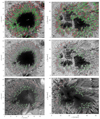 |
Fig. 1. Left: Data set 1 (AR 10930); right: Data set 5 (AR 13014). From top to bottom: (a) Trajectories of inward-moving (green) and outward-moving (red) PGs found by feature tracking from the series of broadband images. Arrows point to the disc center. (b) Positions of visually selected PGs (green, red) in the enhanced continuum images. (c) Maps of LRF magnetic inclination (0°–180°) together with line segments (green, red) representing PGs. White lines show locations where the surrounding inclination was measured. Square symbols at the ends of green/red line segments mark class 1 PGs and dots class −1 ones. |
At first glance, it would seem that the positions of INW and OUT PGs determined by feature tracking can be directly transferred onto magnetic inclination maps to compare γ inside PGs and in their surroundings. However, this approach is not possible because the structures in the spectropolarimetric scans and in the series of broadband images are not synchronized in time. Different parts of the scans are taken at different times. Furthermore, several PGs may be tracked at different times in similar locations in the broadband images. We can only associate the magnetic inclination map with those PGs that were present when the given part of the map was scanned. This problem can be solved by visual identification of PGs in continuum maps derived from the spectral scans and the use of feature-tracking results merely to distinguish the INW PGs from the OUT PGs. A local correlation tracking (LCT, November & Simon 1988) was also used for this purpose as a complementary method.
We selected the PGs visually in continuum images magnified two times (except for data set 3 where the spatial sampling is more than twice as fine as in the rest of the data sets) and enhanced by unsharp masking. The selected PGs had to be clearly recognized as the bright heads of penumbral filaments. Moreover, they had to be located in regions with a well-defined direction of PGs’ motion to differentiate between the INW and OUT PGs, and the local azimuth, ϕ, had to be oriented parallel to the local direction of penumbral filaments. In data set 4, where the broadband observations were missing, the PGs’ motions were estimated by comparison of the PGs’ positions in the two continuum maps (cf. Sect. 2). The positions of selected PGs (green – INW, red – OUT) are shown in Fig. 1b (middle row) for data sets 1 and 5. The inward-moving PGs are located mostly in the inner penumbra and the outward-moving ones in the outer penumbra. Total numbers of the selected INW and OUT PGs in each data set are listed in Table 2.
Numbers of penumbral grains (PGs) in classes −1, 0, 1.
The magnetic field inclination in PGs was retrieved from the LRF inclination maps. Here, the PGs are represented by line segments with a length, l, and centers at the positions selected in continuum images. The orientation of the line segments was determined by the local magnetic field azimuth. The inclination, γPG, is the mean of values along the line segment in the inclination map. The inclination, γs, in the surroundings of each PG was measured along two parallel lines of the same length, l, placed on opposite sides at a distance, d, from the PG line segment. Inclination maps of data sets 1 and 5 together with the positions of line segments (INW PGs – green, OUT PGs – red, surroundings – white) are depicted in Fig. 1c, bottom row. We can see in the figure that the selected PGs mostly coincide with the ends of elongated regions with an increased inclination, which is consistent with the models of filaments proposed by Tiwari et al. (2013).
The mean inclinations along the two surrounding lines were compared to γPG. We define three classes used in this comparison. Class −1: γPG < γs, that is, the inclination in a PG is smaller than the inclinations in the surroundings on both sides (the magnetic field is more vertical in the PG than in the surroundings). Class 0: unsolved cases, when γPG lies between the values of inclination on the sides or it is equal to one of them or to both. Class 1: γPG > γs, that is, the inclination in a PG is larger than the inclinations in the surroundings on both sides (the magnetic field is more horizontal in the PG than in the surroundings).
4. Results
We study the frequencies of occurrence of the INW and OUT PGs in the three classes of magnetic inclination defined above. According to the previous works (e.g., Muller 1973; Sobotka et al. 1999; Zhang & Ichimoto 2013), the length of PGs is 0 6–2″ and their width 0
 3–0
3–0 5. These values can be used for an initial estimate of the parameters l and d introduced in Sect. 3. Because the typical size of structures in the inclination maps varies from one data set to another, the parameters l and d have been refined to minimize the number of unsolved cases (class 0). Numbers of PGs falling into the three classes, together with the used values of the parameters, are listed in Table 2 for each data set. In Fig. 1c, PGs belonging to class 1 (class −1) are marked by small squares (dots) at the inner ends of the green or red line segments, respectively. The absence of symbols means class 0.
It can be seen from Table 2 that the inward-moving PGs fall most frequently into class 1 and least frequently into class −1. This means that the cases where the magnetic inclination in INW PGs is larger than that in the surroundings are statistically dominant. Unresolved cases (class 0) dominate in the data set 3 but the number of class 1 PGs is still larger than that of class −1 ones. The outward-moving PGs fall most frequently into class −1 and least frequently into class 1, so that the statistically dominant situation is when the magnetic inclination in OUT PGs is smaller than that in the surroundings.
A histogram of the relative frequencies of occurrence in the three classes for the whole sample of INW and OUT PGs is plotted in Fig. 2. Of 444 inward-moving PGs, 43.3% have a magnetic inclination larger than that in their surroundings, 21.8% smaller, and 34.9% are unsolved cases. Of 269 outward-moving PGs, 50.5% have an inclination smaller than that in their surroundings, 18.6% larger, and 30.9% unknown. We can conclude that approximately one half of observed PGs comply with the hypothesis proposed by Sobotka & Puschmann (2022), where γPG > γs for INW PGs and γPG < γs for OUT PGs, while only approximately one fifth of the observed PGs are inconsistent with that.
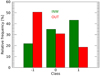 |
Fig. 2. Comparison of the magnetic field inclinations, γPG, of all 713 PGs to the surrounding inclinations, γs. Class −1: γPG < γs; class 0: unsolved cases; class 1: γPG > γs. Green – inward-moving PGs; red – outward-moving PGs. |
Individual PG class distributions based on the radial location within the penumbra, disregarding the direction of motion, are shown in Fig. 3. Data sets 1–4 obtained for approximately regular sunspots were used to make the histogram. The distances of PGs from the umbra-penumbra boundary in each individual penumbra were normalized to a common relative scale from 0 to 1 (inner to outer penumbral boundary). It can be seen that class 1 PGs are concentrated mainly in the inner penumbra, class −1 in the outer penumbra, and class 0 (unsolved cases) are distributed everywhere, but most frequently in the middle penumbra. This is consistent with the semi-empirical models of penumbral filaments by Tiwari et al. (2013).
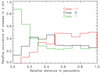 |
Fig. 3. Histogram of relative occurrences of PG classes at different relative distances in the penumbra (0: inner penumbral boundary, 1: outer penumbral boundary). The colors mark class −1 (red), class 0 (black), and class 1 (green). |
The inward-moving PGs complying with γPG > γs (class 1) are observed mainly in the inner penumbra where, according to the LRF inclination maps, the surrounding magnetic inclination, γs, varies between 35° and 65° and the INW PGs are, on average, more inclined by 8° ±4° with respect to the surrounding inclination. The outward-moving PGs complying with γPG < γs (class −1) appear mainly in the outer penumbra, with γs being in the range 65°–90°, and they are less inclined by −13° ±7° on average. The minority classes, class −1 for INW PGs and class 1 for OUT PGs, are observed in regions with γs between 60° and 95° and their average differences in inclinations, γPG − γs, are −12° ±7° and 10° ±6°, respectively. In spite of diverse instruments, observing parameters, spectral lines, and inversion codes, the individual results obtained from data sets 1–5 are similar each to other and are well represented by the above values.
5. Discussion and conclusions
Penumbral filaments are observed everywhere in the penumbra and their bright heads, PGs, host upflows of hot gas from sub-photospheric layers. Tiwari et al. (2013) found that the filaments have essentially the same structure, particularly in the PGs, which are places where the magnetic inclination along the filament is the most vertical, around 50°. Nevertheless, this is valid only for the filaments themselves, because conditions in their surroundings vary substantially with radial distance from the umbra. In particular, γs increases from approximately 35° at the umbra-penumbra boundary to about 90° at the penumbra-granulation border. This increase is weaker for γPG according to our observations, as seen from the average differences, γPG − γs = 8° in the inner penumbra and −13° in the outer one. This is illustrated in a schematic sketch in Fig. 4. Our results are consistent with Tiwari et al.’s picture of penumbral filaments and extend it, including the apparent motion of PGs.
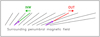 |
Fig. 4. Sketch of statistically dominant inclinations of inward-moving (green) and outward-moving (red) PGs and the inclination of the surrounding penumbral magnetic field. Green and red arrows show the directions of apparent motions of PGs and magenta arrows depict rising flows of gas. |
We utilized five data sets of high-resolution spectropolarimetric observations obtained with one space-born and two large ground-based telescopes to examine the relation between the magnetic field inclination in and around PGs and the direction of the apparent motion of PGs. Sobotka & Puschmann (2022) suggest (cf. Sect. 1) that when the magnetic inclination of a PG is more horizontal than that in its surroundings, the PG moves INW, toward the umbra, and when it is more vertical, the PG moves OUT, away from the umbra (Fig. 4). We find that approximately one half of 713 PGs under study really move according to this scenario. On the other hand, approximately one fifth of PGs show opposite directions of motions and in approximately 30% of PGs, the relation between magnetic inclinations in PGs and their surroundings is unclear.
There may be several reasons for this uncertainty. In some cases, the spatial resolution may not suffice to discern subtle variations of Stokes parameters in and around PGs, particularly in the inner penumbra where magnetic structures are packed more tightly than in the outer one. In the middle penumbra, the difference of magnetic inclinations in and around PGs is expected to be small and may be unresolved (cf. Figs. 3 and 4). Moreover, the accuracy of the inversion results, among them γ and ϕ, depends on the number of used spectral lines. For this reason, data set 3 has a large number of class 0 (unsolved) INW PGs because only one photospheric line is available, unlike two lines in the other data sets. Observations at the 4-metre class telescopes (Inouye Solar Telescope and European Solar Telescope) should provide more data with better spatial resolution and polarimetric accuracy.
Our observational results show a statistical relation between the direction of apparent motions of PGs, which are locations of rising hot gas from sub-photospheric layers, and the inclination of the surrounding magnetic field in the sunspot penumbra. Numerical simulations of penumbral convection are needed to verify that.
Acknowledgments
We thank the anonymous referee for valuable comments, which helped us to improve the paper. This work was supported by the Czech-German common grant, funded by the Czech Science Foundation, grant agreement 23-07633K, and by the Deutsche Forschungsgemeinschaft, grant agreement BE 5771/3-1. We acknowledge the institutional support ASU:67985815 of the Czech Academy of Sciences. GREGOR observations and the GRIS archive were supported by SOLARNET project that has received funding from the European Union Horizon 2020 research and innovation programme under grant agreement no 824135. The CRISP observations were acquired and reduced by S. Esteban Pozuelo and L. Bellot Rubio, with funding from the Spanish Ministerio de Economía y Competitividad through grants AYA2012-39636-C06-05 and ESP2013-47349-C6-1-R, including a percentage from European FEDER funds. The 1.5-metre GREGOR solar telescope was built by a German consortium under the leadership of the Leibniz Institut für Sonnenphysik (KIS) in Freiburg with the Leibniz-Institut für Astrophysik Potsdam, the Institut für Astrophysik Göttingen, and the Max-Planck Institut für Sonnensystemforschung in Göttingen as partners, and with contributions by the Instituto de Astrofísica de Canarias and the Astronomical Institute of the Czech Academy of Sciences. The Swedish 1-m Solar Telescope is operated on the island of La Palma by the Institute for Solar Physics of Stockholm University in the Spanish Observatorio del Roque de los Muchachos of the Instituto de Astrofísica de Canarias. Hinode is a Japanese mission developed and launched by ISAS/JAXA, with NAOJ as domestic partner and NASA and STFC (UK) as international partners. It is operated by these agencies in co-operation with ESA and NSC (Norway).
References
- Castellanos Durán, J. S. 2022, Ph.D. Thesis, University of Göttingen, Germany [Google Scholar]
- Castellanos Durán, J. S., Lagg, A., Solanki, S. K., & van Noort, M. 2020, ApJ, 895, 129 [Google Scholar]
- Castellanos Durán, J. S., Korpi-Lagg, A., & Solanki, S. K. 2023, ApJ, 952, 162 [CrossRef] [Google Scholar]
- Collados, M., López, R., Páez, E., et al. 2012, Astron. Nachr., 333, 872 [Google Scholar]
- de la Cruz Rodríguez, J., Löfdahl, M. G., Sütterlin, P., Hillberg, T., & Rouppe van der Voort, L. 2015, A&A, 573, A40 [NASA ADS] [CrossRef] [EDP Sciences] [Google Scholar]
- Denker, C., Dineva, E., Balthasar, H., et al. 2018, Sol. Phys., 293, 44 [NASA ADS] [CrossRef] [Google Scholar]
- Denker, C., Verma, M., Wiśniewska, A., et al. 2023, J. Astron. Telescopes Instrum. Syst., 9, 015001 [NASA ADS] [Google Scholar]
- Evershed, J. 1909, MNRAS, 69, 454 [Google Scholar]
- Franz, M., & Schlichenmaier, R. 2009, A&A, 508, 1453 [NASA ADS] [CrossRef] [EDP Sciences] [Google Scholar]
- Frutiger, C., Solanki, S. K., Fligge, M., & Bruls, J. H. M. J. 2000, A&A, 358, 1109 [NASA ADS] [Google Scholar]
- Hamedivafa, H., Sobotka, M., Bellot Rubio, L., & Esteban Pozuelo, S. 2016, ArXiv e-prints [arXiv:1612.06636] [Google Scholar]
- Heinemann, T., Nordlund, Å., Scharmer, G. B., & Spruit, H. C. 2007, ApJ, 669, 1390 [Google Scholar]
- Ichimoto, K., Shine, R. A., Lites, B., et al. 2007, PASJ, 59, S593 [NASA ADS] [Google Scholar]
- Ichimoto, K., Lites, B., Elmore, D., et al. 2008, Sol. Phys., 249, 233 [Google Scholar]
- Joshi, J., Pietarila, A., Hirzberger, J., et al. 2011, ApJ, 734, L18 [Google Scholar]
- Kosugi, T., Matsuzaki, K., Sakao, T., et al. 2007, Sol. Phys., 243, 3 [Google Scholar]
- Kuckein, C., Denker, C., Verma, M., et al. 2017, in Fine Structure and Dynamics of the Solar Atmosphere, eds. S. Vargas Domínguez, A. G. Kosovichev, P. Antolin, & L. Harra, IAU Symp., 327, 20 [Google Scholar]
- Lites, B. W., & Ichimoto, K. 2013, Sol. Phys., 283, 601 [Google Scholar]
- Lites, B. W., Elmore, D. F., Seagraves, P., & Skumanich, A. P. 1993, ApJ, 418, 928 [NASA ADS] [CrossRef] [Google Scholar]
- Lites, B. W., Low, B. C., Martinez Pillet, V., et al. 1995, ApJ, 446, 877 [Google Scholar]
- Muller, R. 1973, Sol. Phys., 29, 55 [NASA ADS] [CrossRef] [Google Scholar]
- November, L. J., & Simon, G. W. 1988, ApJ, 333, 427 [Google Scholar]
- Rempel, M. 2012, ApJ, 750, 62 [Google Scholar]
- Rimmele, T., & Marino, J. 2006, ApJ, 646, 593 [NASA ADS] [CrossRef] [Google Scholar]
- Ruiz Cobo, B., & del Toro Iniesta, J. C. 1992, ApJ, 398, 375 [Google Scholar]
- Scharmer, G. B. 2006, A&A, 447, 1111 [NASA ADS] [CrossRef] [EDP Sciences] [Google Scholar]
- Scharmer, G. B., Bjelksjo, K., Korhonen, T. K., Lindberg, B., & Petterson, B. 2003, in Innovative Telescopes and Instrumentation for Solar Astrophysics, eds. S. L. Keil, & S. V. Avakyan, SPIE Conf. Ser., 4853, 341 [NASA ADS] [CrossRef] [Google Scholar]
- Scharmer, G. B., Nordlund, Å., & Heinemann, T. 2008, ApJ, 677, L149 [NASA ADS] [CrossRef] [Google Scholar]
- Scharmer, G. B., Henriques, V. M. J., Kiselman, D., & de la Cruz Rodríguez, J. 2011, Science, 333, 316 [Google Scholar]
- Schlichenmaier, R., Jahn, K., & Schmidt, H. U. 1998a, ApJ, 493, L121 [NASA ADS] [CrossRef] [Google Scholar]
- Schlichenmaier, R., Jahn, K., & Schmidt, H. U. 1998b, A&A, 337, 897 [NASA ADS] [Google Scholar]
- Schmidt, W., von der Lühe, O., Volkmer, R., et al. 2012, Astron. Nachr., 333, 796 [Google Scholar]
- Sobotka, M., & Puschmann, K. G. 2022, A&A, 662, A13 [NASA ADS] [CrossRef] [EDP Sciences] [Google Scholar]
- Sobotka, M., & Sütterlin, P. 2001, A&A, 380, 714 [NASA ADS] [CrossRef] [EDP Sciences] [Google Scholar]
- Sobotka, M., Brandt, P. N., & Simon, G. W. 1997, A&A, 328, 682 [NASA ADS] [Google Scholar]
- Sobotka, M., Brandt, P. N., & Simon, G. W. 1999, A&A, 348, 621 [NASA ADS] [Google Scholar]
- Solanki, S. K. 1987, Ph.D. Thesis, ETH, Zürich, Switzerland [Google Scholar]
- Tiwari, S. K., van Noort, M., Lagg, A., & Solanki, S. K. 2013, A&A, 557, A25 [NASA ADS] [CrossRef] [EDP Sciences] [Google Scholar]
- Tiwari, S. K., van Noort, M., Solanki, S. K., & Lagg, A. 2015, A&A, 583, A119 [NASA ADS] [CrossRef] [EDP Sciences] [Google Scholar]
- Tsuneta, S., Ichimoto, K., Katsukawa, Y., et al. 2008, Sol. Phys., 249, 167 [Google Scholar]
- van Noort, M. 2012, A&A, 548, A5 [NASA ADS] [CrossRef] [EDP Sciences] [Google Scholar]
- van Noort, M., Lagg, A., Tiwari, S. K., & Solanki, S. K. 2013, A&A, 557, A24 [NASA ADS] [CrossRef] [EDP Sciences] [Google Scholar]
- Zhang, Y., & Ichimoto, K. 2013, A&A, 560, A77 [NASA ADS] [CrossRef] [EDP Sciences] [Google Scholar]
All Tables
All Figures
|
Fig. 1. Left: Data set 1 (AR 10930); right: Data set 5 (AR 13014). From top to bottom: (a) Trajectories of inward-moving (green) and outward-moving (red) PGs found by feature tracking from the series of broadband images. Arrows point to the disc center. (b) Positions of visually selected PGs (green, red) in the enhanced continuum images. (c) Maps of LRF magnetic inclination (0°–180°) together with line segments (green, red) representing PGs. White lines show locations where the surrounding inclination was measured. Square symbols at the ends of green/red line segments mark class 1 PGs and dots class −1 ones. |
| In the text | |
|
Fig. 2. Comparison of the magnetic field inclinations, γPG, of all 713 PGs to the surrounding inclinations, γs. Class −1: γPG < γs; class 0: unsolved cases; class 1: γPG > γs. Green – inward-moving PGs; red – outward-moving PGs. |
| In the text | |
|
Fig. 3. Histogram of relative occurrences of PG classes at different relative distances in the penumbra (0: inner penumbral boundary, 1: outer penumbral boundary). The colors mark class −1 (red), class 0 (black), and class 1 (green). |
| In the text | |
|
Fig. 4. Sketch of statistically dominant inclinations of inward-moving (green) and outward-moving (red) PGs and the inclination of the surrounding penumbral magnetic field. Green and red arrows show the directions of apparent motions of PGs and magenta arrows depict rising flows of gas. |
| In the text | |
Current usage metrics show cumulative count of Article Views (full-text article views including HTML views, PDF and ePub downloads, according to the available data) and Abstracts Views on Vision4Press platform.
Data correspond to usage on the plateform after 2015. The current usage metrics is available 48-96 hours after online publication and is updated daily on week days.
Initial download of the metrics may take a while.