| Issue |
A&A
Volume 671, March 2023
|
|
|---|---|---|
| Article Number | A165 | |
| Number of page(s) | 14 | |
| Section | Planets and planetary systems | |
| DOI | https://doi.org/10.1051/0004-6361/202243190 | |
| Published online | 22 March 2023 | |
From exo-Earths to exo-Venuses: Flux and polarization signatures of reflected light
1
Faculty of Aerospace Engineering, Delft University of Technology,
Delft, The Netherlands
e-mail: This email address is being protected from spambots. You need JavaScript enabled to view it.
2
CNRS/INSU, LATMOS-IPSL,
Guyancourt, France
Received:
25
January
2022
Accepted:
9
January
2023
Abstract
Context. Terrestrial-type exoplanets in or near stellar habitable zones appear to be ubiquitous. It is, however, unknown which of these planets have temperate, Earth-like climates or for example, extreme Venus-like climates.
Aims. Technical tools to distinguish different kinds of terrestrial-type planets are crucial for determining whether a planet could be habitable or incompatible with life as we know it. We aim to investigate the potential of spectropolarimetry for distinguishing exo-Earths from exo-Venuses.
Methods. We present numerically computed fluxes and degrees of linear polarization of starlight that is reflected by exoplanets with atmospheres in evolutionary states ranging from similar to the current Earth to similar to the current Venus, with cloud compositions ranging from pure water to 75% sulfuric acid solution, for wavelengths between 0.3 and 2.5 µm. We also present flux and polarization signals of such planets in stable but spatially unresolved orbits around the star Alpha Centauri A.
Results. The degree of polarization of the reflected starlight shows larger variations with the planetary phase angle and wavelength than the total flux. Across the visible, the largest degree of polarization is reached for an Earth-like atmosphere with water clouds due to Rayleigh scattering above the clouds and the rainbow feature at phase angles near 40°. At near-infrared wavelengths, the planet with a Venus-like CO2 atmosphere and thin water cloud shows the most prominent polarization features due to Rayleigh-like scattering by the small cloud droplets. A planet in a stable orbit around Alpha Centauri A would leave temporal variations on the order of 10−13 W m s−1 in the total reflected flux and 10−11 in the total degree of polarization as the planet orbits the star and assuming a spatially unresolved star-planet system. Star-planet contrasts are on the order of 10−10 and vary proportionally with planetary flux.
Conclusions. Current polarimeters appear to be incapable to distinguish between the possible evolutionary phases of spatially unresolved terrestrial exoplanets, as a sensitivity close to 10−10 would be required to discern the planetary signal given the background of unpolarized starlight. A telescope or instrument capable of achieving planet-star contrasts lower than 10−9 should be able to observe the large variation of the planets resolved degree of polarization as a function of its phase angle and thus be able to discern an exo-Earth from an exo-Venus based on their clouds unique polarization signatures.
Key words: radiative transfer / polarization / planets and satellites: atmospheres
Now at SRON Netherlands Institute for Space Research, Leiden, The Netherlands.
© The Authors 2023
 Open Access article, published by EDP Sciences, under the terms of the Creative Commons Attribution License (https://creativecommons.org/licenses/by/4.0), which permits unrestricted use, distribution, and reproduction in any medium, provided the original work is properly cited.
This article is published in open access under the Subscribe to Open model. This email address is being protected from spambots. You need JavaScript enabled to view it. to support open access publication.
1 Introduction
Despite having similar sizes and being formed around the same time and from similar materials, it is clear that the Earth and Venus have evolved into dramatically different worlds. While it is generally acknowledged that Venus once had much larger amounts of water than today, it is still debated whether Venus was once more Earth-like with oceans of water before the runaway-greenhouse-effect took off (Donahue et al. 1982), or whether the atmospheric water vapour never actually condensed on the surface (Turbet et al. 2021). Bullock & Grinspoon (2001) conducted a detailed study of the possible evolution of Venus’s climate over long time periods starting with a water-vapour-enriched atmosphere. Terrestrial-type exoplanets are also expected to harbour a wide variety of atmospheric compositions with maybe only a few planets hospitable to life as we know it. Various climate models suggest that the likelihood of a planetary atmosphere exhibiting a Venus-like runaway-greenhouse-effect is higher than that of an atmosphere in an Earth-like, N2-dominated state (Lincowski et al. 2018, and references therein). A study by Kane et al. (2020) even shows that Jupiter’s migration might have stimulated the runaway-greenhouse-effect on Venus, suggesting that there could be more Venus-analogues than Earth-analogues in planetary systems with Jupiter-like planets.
As planned powerful telescopes and dedicated, sensitive detection techniques will allow us to characterize smaller exo-planets in the near-future, it will become possible to probe terrestrial-type planets in and near the habitable zones of solartype stars and to find out whether they resemble Earth or Venus, or something else altogether. The high-altitude cloud deck on an exo-Venus would make it difficult to use a technique like transit spectroscopy for the characterization of the planet as the clouds themselves would block the transmission of the starlight and apart from a spectral dependence of the cloud optical thickness which could leave a wavelength dependent transmission through the cloud tops, the microphysical properties of the cloud particles, such as their composition, shape and size distribution would remain a mystery. Also, the clouds would inhibit measuring trace gas column densities as they would block the planet’s lower atmosphere and only allow transit spectroscopy of the highest regions of the atmosphere (see e.g. Lustig-Yaeger et al. 2019a, and references therein). Indeed, a Venus-like ubiquitous cloud deck could possibly be mistaken for the planet’s surface, as one would only measure the transmittance through the gaseous atmosphere above the clouds, possibly inferring the atmosphere to be thin and eroding (Lustig-Yaeger et al. 2019b).
Jordan et al. (2021) modeled the photochemistry of some of the primary sulphuric chemical species responsible for the formation and sustenance of Venus’s sulfuric acid solution clouds, such as SO2, OCS and H2S; they found that the abundances of such species above the cloud deck would depend heavily on the effective temperature and distance to the parent star, with their abundances decreasing with increasing temperature and being depleted, as we see on Venus, in the presence of a star such as the Sun. Thus, it would be challenging to rule out the possibility of an exoplanet being a Venus analogue solely on the basis of the detection of such chemical species in transmission spectra (Jordan et al. 2021). Indeed, the full characterization of rocky exoplanets and their classification appears to require the direct imaging of starlight that is reflected by such planets or the thermal radiation that is emitted by them. While telescopes able to perform such measurements are not yet available, plans are underway for their development and deployment (Keller et al. 2010; LUVOIR Team 2019).
While most of telescopes and instruments are designed for only measuring total fluxes of exoplanets, the inclusion of (spec-tro)polarimetry is also being considered. The main reason to include (spectro)polarimetry (see e.g. Rossi et al. 2023, and references therein) is that it increases the contrast between star and planet; this is because the stellar flux will be mostly unpolarized when integrated over the disk (Kemp et al. 1987), while the flux of the reflected starlight will usually be (linearly) polarized. In addition, (spectro)polarimetry can be used for the characterization of planetary atmospheres and surfaces. As a classic example of the latter, Hansen & Hovenier (1974) used Earth-based measurements of the disk-integrated degree of polarization of sunlight that was reflected by Venus in three spectral bands and across a broad phase-angle range, to deduce that the particles forming Venus’s main cloud deck consist of 75% sulfuric acid solution, that the effective radius of their size distribution is 1.05 µm, and that the effective width of the distribution is 0.07. They also derived the cloud top altitude (at 50 mbars) by determining the amount of Rayleigh scattering in the gas above the cloud tops at a wavelength of 0.365 µm. This was later confirmed by the Pioneer Venus mission, which performed in situ measurements using a nephelometer on a probe that descended through the clouds (Knollenberg & Hunten 1980).
Polarimetry proved to be an effective technique for disentangling Venus’s cloud properties because the scattering particles leave a unique angular polarization pattern in the reflected sunlight depending on the particles’ micro- and macro-physical properties (for an extensive explanation of the application of polarimetry for the characterization of planetary atmospheres, see Hansen & Travis 1974). While multiple scattered light usually has a low degree of polarization, and thus dilutes the angular polarization patterns of the singly scattered light, the angles where the absolute degree of polarization reaches a local maximum or where it is zero (the so-called neutral points) are preserved and thus still allow for the characterization of the particles.
Another factor in the successful application of (spec-tro)polarimetry for the characterization of Venus’s clouds and hazes is that with Earth-based telescopes, inner planet Venus can be observed at a wide range of phase angles, thus allowing observations of the angular variation of the degree of polarization due to the light that has been singly scattered by the atmospheric constituents. In our solar system, only Venus, Mercury, and the Moon can be observed at a large phase-angle range with Earth-based telescopes (ignoring the proximity of Mercury to the Sun). To effectively apply polarimetry to the outer planets in the Solar System, a polarimeter onboard a space instrument would be needed. An example of such an instrument was OCCP onboard NASA’s Galileo mission (Russell et al. 1992) that orbited Jupiter. Regarding exoplanets, however, the range of observable phase angles depends on the inclination angle of the planetary orbits; for a face-on orbit, the planet’s phase angle will be 90° everywhere along the orbit, while for an edge-on orbit, the phase angle will range from close to 0° (when the planetary disk is fully illuminated) to 180° (when the night-side of the planet is in view). The precise range of accessible phase angles would of course depend on the observational technique and for example the use of a coronagraph or star-shade.
Here, we investigate the total flux and degree of polarization of starlight that is reflected by terrestrial-type exoplanets, focusing on the possible evolutionary stages of Venus as described by Bullock & Grinspoon (2001). Our goal is to identify characteristic signatures that could help to identify the properties of exo-Venuses, thus to guide the design of future telescope instruments. We computed the disk-integrated total and polarized fluxes of light reflected between wavelengths of 0.3 and 2.5 µm. First, we studied the single-scattering properties of spherical cloud droplets of pure water (H2O) or 75% sulphuric acid (H2SO4) in order to identify potentially distinct signatures for each particle type as a function of wavelength and planetary phase angle. Second, we computed the multiple scattered flux and polarization signals that are integrated over the planet’s illuminated disk as functions of the planet’s phase angle. Third, we computed the signals of the planets in the four evolutionary phases in stable orbits around the nearby solar-type Alpha Centauri A, simulating the observations of such planets if they are spatially unresolved from their parent star.
The outline of this paper is as follows. In Sect. 2, we define the fluxes and polarization of planets, and we describe our numerical algorithm and the four model planets in the evolutionary phases as described by Bullock & Grinspoon (2001). In Sect. 3, we present the total and polarized fluxes as computed for planets that are spatially resolved from their star and for planets that are spatially unresolved. In the latter case, the planet’s signal is thus combined with the stellar light. We assume that our model planet orbits the solar-type star Alpha Centauri A. In Sect. 4, we summarize our results and present our conclusions.
2 Numerical method
2.1 Flux and polarization definitions
In this paper, we present the flux and polarization signals of starlight that is reflected by potentially habitable exoplanets that orbit solar-type stars, and in particular, Alpha Centauri A. Because these planets are very close in angular distance to their parent star, they are usually spatially unresolved, that is it will not be possible to spatially separate the planet’s signal from that of its parent star. The flux vector Fu (u = ‘unresolved’) that describes the light of the star and its spatially unresolved planet, and arrives at a distant observer is then written as
 (1)
(1)
with Fs being the star’s flux vector and Fp that of the planet. Furthermore, λ is the wavelength (or wavelength band), and α is the planetary phase angle, that is the angle between the star and the observer as measured from the centre of the planet. We assume that the light of the star is captured together with the starlight that is reflected by the planet. A telescope with a corona-graph or star-shade would of course limit the amount of captured direct starlight, depending on its design and the angular distance between the star and the planet.
A flux (column) vector is given by (Hansen & Travis 1974)
![Mathematical equation: ${\bf{F}} = \left[ {F,Q,U,V} \right],$](/articles/aa/full_html/2023/03/aa43190-22/aa43190-22-eq2.png) (2)
(2)
with F being the total flux, Q and U the linearly polarized fluxes, and V the circularly polarized flux. The dimensions of F, Q, U, and V are W m−2, or W m−3 when defined per wavelength.
Measurements of FGK stars, such as the Sun and Alpha Centauri A, indicate that their (disk-integrated) polarized fluxes are virtually negligible (Kemp et al. 1987; Cotton et al. 2017); thus, we describe the star’s flux (column) vector that arrives at the observer located at a distance D as
 (3)
(3)
with πB being the stellar surface flux, Ts the star’s effective temperature, Rs the stellar radius, and 1 the unit (column) vector. The parameter values that we adopt for the Alpha Centauri A system are listed in Table 1.
Because of the huge distances to stars and their planets, flux vector Fp of the starlight that is reflected by an exoplanet pertains to the planet as a whole, thus integrated across the illuminated and visible part of the planetary disk. It is given by (see e.g. Rossi et al. 2018)
 (4)
(4)
 (5)
(5)
Here, AG is the planet’s geometric albedo, Rp the matrix describing the reflection by the planet and R1p its first column, rp is the planet’s radius, d the distance between the star and the planet, and D the distance to the observer. The planet’s reflection is normalized such that planetary phase function R1p, which is the first element of R1p, equals 1.0 at α = 0°.
The contrast C between the total flux of the planet and the total flux of the star is then given by
 (6)
(6)
with Fp being the first element of the planetary flux vector Fp. Using the parameters from Table 1, the contrast C between a planet with the radius of Venus at a Venus-like distance from Alpha Centauri A equals about 2 × 10⁻⁹AG at α = 0° (at this phase angle, the planet would actually be behind the star with respect to the observer and thus out of sight).
The degree of polarization of the spatially resolved planet (without including any direct light of the star) is defined as where we ignore the planet’s circularly polarized flux Vp as it is expected to be very small compared to the linearly polarized fluxes (Rossi & Stam 2018). We also ignore the circularly polarized fluxes in our radiative transfer computations, as this saves significant amounts of computing time without introducing significant errors in the computed total and linearly polarized fluxes (see Stam & Hovenier 2005).
 (7)
(7)
Fluxes Qp and Up are defined with respect to the planetary scattering plane, which is the plane through the planet, the star, and the observer. If the planet is mirror-symmetric with respect to the planetary scattering plane, the linearly polarized flux Up equals zero and we can use an alternative definition of the degree of polarization that includes the polarization direction as follows:
 (8)
(8)
If Pp > 0 (Pp < 0), the light is polarized perpendicular (parallel) to the reference plane.
In case a planet is not completely spatially resolved from its parent star and the background of the planet on the sky is thus filled with (unpolarized) starlight, the observable degree of polarization Pu can be written as (see Eqs. (6)–(7))
 (9)
(9)
with x being the fraction of the stellar flux that is in the background, which will depend on the angular distance between the star and the planet, on the starlight suppressing techniques that are employed such as a coronagraph or star-shade, and on the spatial resolution of the telescope at the wavelength under consideration. This equation also holds for the signed degree of polarization as given by Eq. (8). If x = 1, the planetary and the stellar flux are measured together. In that case,
 (10)
(10)
Here we used the fact that the contrast C will usually be very small (on the order of 10−9 as shown earlier).
The planet’s degree of polarization Pp and the contrast C both depend on λ and α, but generally in a different way. The dependence of Pu on λ and α will thus generally differ from that of either Pp or C.
Values of the parameters describing the planetary system of Alpha Centauri A used in our numerical modeling.
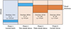 |
Fig. 1 Four evolutionary phases of the model planets (Bullock & Grinspoon 2001). In Phases 1 and 2, the clouds consist of liquid water droplets, and in Phases 3 and 4, they consist of liquid sulfuric acid solution droplets. The cloud optical thickness is indicated by bc and the cloud particle effective radius by reff. For the effective variance υeff of the size distributions in Phases 1–3, we used 0.1, and for Phase 4 we used υeff = 0.07. |
2.2 Our radiative transfer algorithm
Our procedure to compute the flux vector Fp (Eq. (5)) of the starlight that is reflected by the planet, is described in Rossi et al. (2018). The radiative transfer algorithm is based on an efficient adding-doubling algorithm (de Haan et al. 1987) and fully includes polarization for all orders of scattering. With this algorithm, through the use of a Fourier-series expansion of the planetary reflection matrix Rp, the reflected flux vector can be computed for any planetary phase angle α.
Our model planetary atmospheres consist of horizontally homogeneous layers. For each layer, we prescribe the total optical thickness b, the single-scattering albedo a, and the single-scattering matrix P. Our layered model atmosphere is bounded below by a Lambertian reflecting surface (that is, the light is reflected isotropically and is unpolarized) with an albedo asurf.
A layer’s optical thickness b at a wavelength λ is the sum of the optical thicknesses of the gas molecules, bm, and, if present, the cloud particles, bc. We ignore other atmospheric particles, such as haze particles. The single-scattering matrix P of a mixture of gas molecules and cloud particles in a layer is given by
 (11)
(11)
with subscript ‘sca’ referring to ‘scattering’; thus, bsca = ab, with a being the single-scattering albedo. Furthermore, Pm is the single-scattering matrix of the gas molecules, and Pc that of the cloud particles. Θ is the single-scattering angle: Θ = 180° – α.
We used two types of model atmospheres to study the influence of an exoplanet’s atmospheric evolution on the reflected light signals: an Earth-like and a Venus-like atmosphere. For our Earth-like atmosphere, we defined the pressure and temperature across 17 layers, representing a mid-latitude summer profile (following Stam 2008). For our Venus-like atmosphere, we used 71 layers with pressure and temperature profiles from the Venus International Reference Atmosphere (VIRA; Kliore et al. 1985), representing a mid-latitude afternoon profile. With these vertical profiles, and assuming anisotropic Rayleigh scattering (Hansen & Travis 1974), we computed each layer’s single-scattering matrix Pm and the scattering optical thickness  . We neglect absorption, thus
  . The depolarization factor for computing Pm and
  for anisotropic Rayleigh scattering depends on the atmospheric composition. For the Earth-like atmosphere, we used a (wavelength independent) depolarization factor of 0.03, which is representative for dry air, and for the Venus-like atmosphere, we used 0.09, which is representative for a pure CO2 atmosphere (Hansen & Travis 1974). We used wavelength-independent refractive indices of 1.00044 and 1.00027 for the Venus-like and the Earth-like model atmospheres, respectively; note that this assumption has a negligible effect on the reflected total and polarized fluxes.
The cloud particles in our model atmospheres are spherical and distributed in size according to a two-parameter gamma size distribution (see Hansen & Travis 1974) that is described by an effective radius reff and an effective variance υeff. The terrestrial clouds are located between 1 and 3 km in altitude, and the Venu-sian clouds, depending on their evolutionary phase, between 47 and 80 km. The cloud optical thickness has a uniform vertical distribution through the altitude range (see Fig. 1).
The single-scattering properties of the cloud particles are computed using Mie-theory (De Rooij & Van der Stap 1984), as these particles are expected to be spherical. For these computations we specify the wavelength λ and nr, which represent the refractive index of the cloud particles. The cloud particles are composed of either pure water or a sulphuric acid solution with varying concentration. We used the refractive index of water from Hale & Querry (1973) and that of sulphuric acid with 75% acid concentration from Palmer & Williams (1975). We used a negligible value for the imaginary part of the particles’ refractive indices: ni = 10−8.
2.3 Cloud properties through the planet’s evolution
It is suspected that early Venus had a thin, Earth-like atmosphere and (possibly) an Earth-like ocean that was later lost due to the runaway greenhouse effect (Donahue et al. 1982; Kasting 1988; Way & Del Genio 2020). As the planet’s surface heated up, the water would have evaporated and enriched the atmosphere with water vapor. The macroscopic cloud properties for the four evolutionary phases that we used are illustrated in Fig. 1.
We started our evolutionary model of Venus assuming Earthlike conditions (Phase 1), that is an atmosphere consisting of 78% N2 and 22% O2. Model simulations showed that the actual dependence of the total and polarized flux signals on the percentage of oxygen appeared to be negligible. Hence we used the present-day Earth atmosphere as the Earth-like atmosphere model while the actual percentage of oxygen on an exoplanet could be different. The cloud particles have an effective radius reff of 10 µm in agreement with ISCCP (Tselioudis 2001), and an effective variance υeff of 0.1. The total cloud optical thickness bc is 10.0 at λ = 0.55 µm and the cloud layer extends from 2 to 4 km.
The next evolutionary phases are also inspired by the Venus climate model of Bullock & Grinspoon (2001). In Phase 2, the atmosphere is Venus-like as it consists of pure CO2 gas and has relatively thin liquid water clouds with bc = 4, and with the cloud tops at 80 km. For this phase, we use reff of 0.5 µm, which is smaller than the present day value, because the atmosphere is expected to be too hot for strong condensation to take place thus preventing the particles from growing larger. In Phase 3, the clouds are thick sulphuric-acid solution clouds, with bc = 120 and the cloud tops at 65 km, because the atmosphere is cool enough to allow condensation and coalescence of saturated vapor over a large altitude range. Since the region of condensation covers a large altitude range, the particles can grow large until they evaporate. In this phase, reff = 2 µm, which is twice the effective radius of the present day Venus cloud particles.
For both Phases 2 and 3, we used υeff = 0.1. In Phase 4, the clouds have the present-day properties of Venus’s clouds with bc = 30 and the cloud tops at 65 km (Rossi et al. 2015; Ragent et al. 1985). For the cloud particle sizes in this phase, we use reff = 1.05 µm and υeff = 0.07 following the values derived by Hansen & Hovenier (1974). We ignored the absorption by cloud particles in the UV in all of our Venus-like clouds to avoid adding complexity and because the exact nature and location of the UV-absorption is still under debate (Titov et al. 2018).
Figure 2 shows the phase function (that is the single-scattering matrix element P11) and the degree of linear polarization for unpolarized incident light (the ratio of single-scattering matrix elements -P21/P11) that has been singly scattered by the four different types of cloud particles as functions of α (that is 180° – Θ), for a range of wavelengths λ.
As can be seen in Fig. 2, the phase functions show strong forward scattering peaks (near α = 180°, thus when the night-side of the planet would be turned towards the observer) that decrease with increasing λ, thus with decreasing effective particle size parameter xeff = 2πreff/λ (for the large H2O cloud particles, with reff = 10 µm, this decrease is not readily apparent from the figure). The H2O particles with reff = 10 µm show a moderate local maximum in the phase function around α = 40°, which is usually referred to as the primary rainbow (see e.g. Hansen & Travis 1974). The large H2O and the H2SO4 particles also produce higher fluxes toward α = 0° that are referred to as the glory (Laven 2008; García-Muñoz et al. 2014; Markiewicz et al. 2014, 2018; Rossi et al. 2015). For the small H2O particles and the H2SO4 particles at larger wavelengths, the phase functions become more isotropic and the glory and other angular features disappear.
Figure 2 also shows the degree of linear polarization of the singly scattered light. This degree of polarization appears to be more sensitive to the particle composition than the scattered flux, especially for λ between 0.5 and 2 µm, where H2O particles yield relatively high positive degrees of polarization (perpendicular to the scattering plane) between phase angles of about 20° and 100°, whereas the H2SO4 particles impart a mostly negative degree of polarization through a broad range of phase angles, except for narrow regions around α = 20° and 80°. The tiny, reff = 0.5 µm, water droplets have a strong, broad positive polarization region for λ ≥ 1 µm, where they are so small with respect to the wavelength that they scatter similarly to Rayleigh scatterers.
As mentioned before (see e.g. Hansen & Travis 1974; Hansen & Hovenier 1974), patterns in the single-scattering degree of polarization are generally preserved when multiple scattered light is added, as the latter usually has a low degree of polarization, and thus adds mostly total flux, which subdues angular features but does not change the angular pattern (local maxima, minima, neutral points) itself. The single-scattering angular features in the polarization will thus also show up in the polarization signature of a planet as a whole, and it can be used for characterization of the cloud particle properties and thus possibly of various phases in the evolution of a Venus-like exoplanet. This is investigated in the next section.
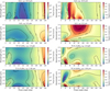 |
Fig. 2 Total flux and degree of polarization of incident unpolarized light that has been singly scattered by four different types of cloud particles, as functions of the phase angle α and the wavelength λ. Left column: total flux or phase function (single-scattering matrix element P11). Right column: degree of polarization (−P21/P11). First row: H2O particles with reff = 10 µm and υeff = 0.1 (belonging to the Phase 1 model planet: ‘Current Earth’). Second row: H2O particles with reff = 0.5 µm and υeff = 0.1 (Phase 2: ‘Thin cloud Venus’). Third row: 75% H2SO4 particles with reff = 2.0 µm and υeff = 0.1 (Phase 3: ‘Thick cloud Venus’). Fourth row: 75% H2SO4 particles with reff = 1.05 µm and υeff = 0.07 (Phase 4: ‘Current Venus’). |
3 Results
Here we present the disk-integrated total flux and degree of polarization of incident unpolarized starlight that is reflected by the model planets at different wavelengths λ and for phase angles α ranging from 0° to 180°. The actual range of phase angles at which an exoplanet can be observed depends on the inclination angle i of the planet’s orbit (the angle between the normal on the orbital plane and the direction towards the observer): α ranges from 90° − i to 90° + i. Obviously, at α = 0°, the planet would be precisely behind its star, and at 180° it would be precisely in front of its star (in transit). Other phase angles might be inaccessible due to restrictions of inner working angles of telescopes and/or instruments. For completeness, we include all phase angles in our computations.
Section 3.1 shows results for spatially resolved planets and Sect. 3.2 shows results for planets that are spatially unresolved from their star. In particular, we show these latter results for a model planet orbiting the star Alpha Centauri A at a distance where the incident stellar flux is similar to the solar flux that reaches Venus. Because our model planets are all mirror-symmetric with respect to the reference plane, their linearly polarized flux Up equals zero and will not be discussed further.
3.1 Flux and polarization of spatially resolved planets
Figure 3 shows the total flux Fp (the planetary phase function) and degree of polarization Pp as functions of α and λ for the four evolutionary phases illustrated in Fig. 1. The total fluxes are normalized such that at α = 0°, they equal the planet’s geometric albedo AG (see Eq. (5)). Figure 4 shows AG of the planets in the four evolutionary phases as functions of the wavelength λ. Table 2 lists the geometric albedo’s at 0.5, 1.0, 1.5 and 2.0 µm. The ‘Current Earth’ (Phase 1) shows very little variation in AG, and the ‘Thin cloud Venus’ (Phase 2) has the lowest albedo because of the small cloud particles and the small cloud optical thickness. The geometric albedo’s of the ‘Thick cloud Venus’ (Phase 3) and the ‘Current Venus’ (Phase 4) are very similar. Thus across the wavelength region investigated in this paper, the ‘Current Earth’ (Phase 1) has the highest geometric albedo.
For each model planet, the total flux Fp decreases with increasing α mostly because less of the planet’s observable disk is illuminated. The planet with thin H2O clouds (Phase 2) is very dark over all α’s because the cloud optical thickness bc is small and the surface is black. The total fluxes show vague similarities with the single-scattering phase functions of the cloud particles (Fig. 2). In particular, for the Current Earth (Phase 1) with large H2O particles, Fp increases slightly around α = 40°, the rainbow angle. Also, the decrease of Fp with λ is stronger for the Venus-type planets with H2SO4 clouds (Phases 3 and 4) than for the planet with the large H2O particles (Current Earth, Phase 1), because the single-scattering phase function of the sulfuric acid particles decreases more with λ than that of the water droplets (see Fig. 2).
Unlike Fp, the degree of polarization Pp of each of the model planets shows angular and spectral features that depend strongly on the cloud properties and should thus allow us to distinguish between the different evolutionary phases. In Phase 1 (Current Earth), Pp is high and positive up to λ = 0.5 µm and around α = 90°, which is due to Rayleigh scattering by the gas above the clouds. Starting at the shortest λ, Pp increases slightly with λ before decreasing. This is due to the slightly larger contribution of multiple scattered light, with a lower degree of polarization, at the shortest wavelengths. A Rayleigh-scattering peak is also seen for Phase 4 (Current Venus), except there the peak decreases more rapidly with λ because the clouds are higher in the atmosphere and there is thus less gas above them. In Phase 3 (Thick cloud Venus), the Rayleigh-scattering peak is suppressed by the contribution of low polarized light that is reflected by the thicker clouds below the gas. In Phase 2 (Thin cloud Venus), the relatively thin clouds are higher in the atmosphere than in Phase 1 (Current Earth), which is why the Rayleigh-scattering peak only occurs at the very shortest wavelengths (the peak is hardly visible in Fig. 3). Because the Phase 2 cloud particles are small (reff = 0.5 µm), they themselves give rise to a Rayleigh-scattering peak at λ ≥ 1.0 µm.
The two model planets with the H2 O cloud particles (Phases 1 and 2) show a narrow region of positive polarization between 30° and 40°, which is the rainbow peak (see Fig. 2). On exoplanets, this local maximum in Pp could be used to detect liquid water clouds (Karalidi et al. 2011, 2012; Bailey 2007). In Phase 1 (Current Earth), the rainbow region starts near the Rayleigh scattering peak of the gas and extends towards the largest wavelengths. In Phase 2 (Thin cloud Venus), with the small water droplets, the rainbow only occurs at the shortest wavelengths. With increasing wavelength, it broadens and disappears into the cloud particles’ Rayleigh scattering peak.
The H2SO4 cloud particles (Phases 3 and 4) have their own specific polarization patterns, such as the broad negative polarization region at α ⪆ 80°, which can be traced back to their single-scattering patterns (Fig. 2). In Phase 3 (Thick cloud Venus), the cloud particles give rise to a sharp positive polarization peak at the shortest wavelengths and for 20° ⩽ α ⩽ 30°. In Phase 4 (Current Venus), there is a broader, lower, positive polarization branch across this phase-angle range, which resembles the positive polarization branch of the tiny H2O droplets in Phase 2 (Thin cloud Venus). However, at the longer wavelengths, the phase-angle dependence of the polarization of the latter planet is very different which should help to distinguish between such planets. This emphasizes the need for measurements at a wide range of wavelengths and especially phase angles (if the planet’s orbital inclination angle allows this).
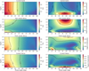 |
Fig. 3 Total flux (or phase function) and degree of polarization of incident unpolarized starlight that is reflected by the model planets in the 4 evolutionary phases as functions of α and λ. Left column: the total flux (or phase function). Right column: degree of polarization. First row: phase 1 (‘Current Earth’). Second row: phase 2 (‘Thin cloud Venus’). Third row: phase 3 (‘Thick cloud Venus’). Fourth row: phase 4 (‘Current Venus’). The phase functions are normalized such that at α = 0°, and they equal the planet’s geometric albedo AG. |
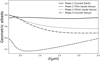 |
Fig. 4 Planets’ geometric albedo’s AG as functions of the wavelength λ for the four evolutionary phases. |
Model planets’ geometric albedos AG for the four evolutionary phases at four wavelengths.
3.2 Flux and polarization of spatially unresolved planets
In the previous section, we show the signals of spatially resolved planets, that is, without background starlight. When observing an exoplanet in the habitable zone of a solar-type star, it is difficult to avoid the starlight. Here, we show the total flux of the planet Fp, the star-planet contrast С (see Eq. (6)), the spatially resolved degree of polarization of the planet Pp (thus without the starlight) and the spatially unresolved degree of polarization of the combined star-planet signal Pu (thus including the starlight). While the total planet fluxes shown in Fig. 3 were normalized at α = 0° to the planets’ geometric albedos AG, here they are computed according to Eq. (5), and thus depend on the parameters of the planet-star system. We assume our model planets orbit Alpha Centauri A.
The solar-type star Alpha Centauri A is part of a double star system, and the orbital parameters of ourplanets are chosen based on the stable planet orbital distances and orbital inclination angles around this star as predicted by Quarles & Lissauer (2016). Figure 5 shows a sketch of the system. We used a planetary orbital distance d of 0.86 AU, such that each model planet receives a stellar flux similar to the solar flux received by Venus. Additional system parameter values are listed in Table 1. According to Quarles & Lissauer (2016), stable orbits around Alpha Centauri A can be found for a range of angles between the planetary orbital plane and the plane in which the two stars orbit, and thus for a range of inclination angles i of the planetary orbit.
Figure 6 shows the variation of the planetary phase angle α along a planetary orbit for two values of the longitude of the orbit’s ascending node Ω: for Ω = 0° (the line connecting the planet’s ascending and descending nodes is perpendicular to the line to the observer) and for Ω = 205° which represents the configuration of Earth with Alpha Centauri A. The orbital phase of the planet is defined such that at an orbital phase angle of 0°, α = 180°. The inclination angle im is the angle between the plane in which the stars move and the planetary orbital plane. For Ω = 0°, im = −10° would yield a face-on planetary orbit (i = 0°) with α = 90° everywhere along the orbit. For im = 80°, the orbit is edge-on (i = 90°) and α varies between 0° and 180°. Figure 6 also shows the range of α for im = 0° and 35°. According to Quarles & Lissauer (2016), the latter is the most probable orientation of a stable planetary orbit. For these two cases, the accessible phase angles range from 80° to 100°, and from 45° to 135°, respectively. For Ω = 205°, the maximum range of α would be from 20° to 160°, depending on im.
Figure 7 shows Fp, Pp, and Pu (the spatially unresolved planet, thus with starlight included) for Phase 4 (Current Venus) as functions of the planet’s orbital phase for Ω = 205°, four values of im (−10°, 80°, 0°, and 35°), and four wavelengths (0.5, 1.0, 1.5, and 2.0 µm). The plots for Fp also show the contrast C. Because С is the ratio of the planetary flux Fp to the stellar flux Fs (Eq. (6)), its variation with the orbital phase is proportional to that of Fp.
At the two orbital phases in each plot where all the lines cross, the planetary phase angles α are the same (see Fig. 6) and thus all Fp and Pp are the same. The plots for Fp appear to be very similar for the different wavelengths, apart from a difference in magnitude, which is mainly due to the decrease of the stellar flux that is incident on the planet with increasing wavelength; however, the planetary albedo AG and phase function R1p also decrease with increasing λ, as can be seen in Fig. 3. This wavelength dependence of Fp also causes the decrease of the contrast C with increasing wavelength (that is, the planet darkens with increasing λ), as C is independent of the wavelength dependence of the stellar flux (see Eq. (6)). The shape differences between the Fp (and C) curves are due to the wavelength dependence of the planetary flux that can also be seen in Fig. 3.
At each wavelength λ, the largest variation in Fp with the orbital phase is seen for im = 80°, because for that configuration the variation of α along the orbit is largest (see Fig. 6). The degree of polarization Pp of the planet shows significant variation with the orbital phase at all wavelengths. A particularly striking feature for the geometry with im = 80° is the double peak close to the orbital phases of 150° and 200°. As can be seen in Fig. 6 for Ω = 205° and im = 80°, α decreases from about 160° at an orbital phase of 0°, to 20° at an orbital phase around 175°, and then increases again with increasing orbital phase. Tracing this path of α through the Pp panel in the bottom row of Fig. 3 explains the double-peaked behaviour of Pp and its wavelength dependence as shown in Fig. 7. For the other values of im, the phase-angle range that is covered along the orbit is smaller, and therefore the variation in Pp is also smaller.
The degree of polarization of the spatially unresolved planet Pu shows similar variations along the orbital phase as Pp, except that most features are flattened out because of the addition of the unpolarized stellar flux, which is independent of the orbital phase angle. The double-peaked feature for im = 80° remains strong; however, as at those orbital phase angles, the contrast C is relatively large, and thus the influence of the added stellar flux is relatively small. The variation in the polarization of the unresolved system due to the orbiting planet is on the order of 10−11.
Figure 8 is similar to Fig. 7, except for the four model planets in the different evolutionary phases having orbital configuration of im = 80° and Ω = 0°. Because the planetary orbits are seen edge-on here (i = 90°), the full range of phase angles is covered, which makes it possible to explore the full extent of variation of flux and polarization signals. Because of this large phase-angle range, Fp varies strongly with the orbital phase. The wavelength dependence of the total flux can be traced back to Fig. 3, where the Phase 2 planet (Thin cloud Venus) in particular is dark at all wavelengths, but relatively bright at the longest wavelengths and small phase angles. As is the case in Fig. 7, the variation of C is the same as that of Fp, except for the offset due to the stellar flux. The largest values of C (about 1.6× 10⁻⁹) are found for λ = 0.5 µm and around the orbital phase of 180° (at 180°, the planets would actually be behind the star).
Furthermore, in Fig. 8, Pp depends strongly on λ and the planet’s evolutionary phase. At 0.5 µm, the Phase 1 planet (Current Earth) shows the largest values of Pp due to the Rayleigh scattering gas above the low-altitude clouds. At the longer wavelengths, where the Rayleigh scattering is less prominent, the curves for the Phase 1 planet clearly show the positive polarization of the rainbow around the orbital phases of 140° and 220° (see Fig. 6). For the Phase 2 planet (Thin cloud Venus) and 0.5 µm, the small cloud particles cause positive polarization around 150° and 210°, which connects the rainbow and the Rayleigh scattering maximum in Fig. 3. At longer wavelengths, the broad positive polarization signature of Rayleigh scattering by the cloud particles dominates the curves, while the curves for the Phases 3 and 4 planets show mostly negative polarization apart from the orbital phases around 180°. When adding the starlight, the angular features of the polarization Pu are suppressed along the parts of the orbits where C is smallest, thus away from the orbital phase angle of 180°. Particularly within 180° ±40°, Pu still shows distinguishing features, although they are very small in the absolute sense (smaller than 10−10).
Figure 9 is similar to Fig. 8 except here the model planets are in the most probable stable orbit around Alpha Centauri A as predicted by Quarles & Lissauer (2016), namely with Ω = 205° and im = 35°. As can be seen in Fig. 6, for this geometry α varies between about 60° and 120°. In Fig. 9, Fp shows a similar variation as the curves in Fig. 8, although it is less prominent, as the planets reach neither a ‘full’ phase (where α = 0°) nor the full night phase (α = 180°) along their orbit. The flux curves in Fig. 9 also lack small angular features that appear in the single-scattering phase functions of the cloud particles (see Fig. 2), such as the glory, again because the planets do not go through the related phase angles.
In this particular orbital geometry, Pp shows less pronounced angular features than for the same model planets in edge-on orbits (Fig. 8) because of the more limited phase-angle range. For example, the Current Earth (Phase 1) shows no rainbow despite the H2O clouds, because the phase angle of about 40° is not reached. In the visible (λ = 0.5 µm), Pp reaches the largest values for the Current Earth (Phase 1). At longer wavelengths, Pp of the Thin cloud Venus (Phase 2) strongly dominates because of the Rayleigh scattering by the small cloud particles. The Thick cloud Venus (Phase 3) shows predominant negative polarization at all wavelengths and across the whole orbital phase-angle range except at λ = 0.5 µm around an orbital phase angle of 20°.
The polarization of the spatially unresolved planets, Pu, clearly shows the suppression of the polarization features due to the added starlight toward the smaller and larger orbital phase angles, where the planets are darker. While the Phase 2 planet (Thin cloud Venus) is relatively dark (C is very small), its Rayleigh scattering polarization signal is so strong that its unresolved polarization signal is larger than that of the other planets, except the Phase 1 planet (Current Earth) at 1.0 µm and orbital phase angles close to 180°.
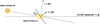 |
Fig. 5 Sketch of geometries within the Alpha Centauri system: the orbital plane of the stars Alpha Centauri A and В is inclined by about 80° with respect to the observer on Earth. Our model planet (the blue dot) orbits Alpha Centauri A. In this sketch, the line of nodes of the planet’s orbit was chosen to coincide with that of the stellar orbits. The inclination angle im of the planet’s orbit with respect to the stellar orbital plane is 45°, and the inclination angle of the planet’s orbit with respect to the observer is 80° − 45° = 35°. The phase angles of the planet in this sketch would range from 90° − 35° = 55° to 90° + 35° = 125°. |
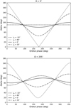 |
Fig. 6 Variation of the planet’s phase angle α along the planet’s orbit around Alpha Centauri A for different mutual inclination angles im of the planetary orbit with respect to the orbital plane of the two stars. Top: Ω, the longitude of the ascending node of the planet’s orbit, is 0°. For im = −10°, the planet is then in a face-on orbit (i = 0°), while for im = 80°, it is in an edge-on orbit (i = 90°). Bottom: Ω = 205°, and the planetary orbit is aligned with the node of the stellar orbital plane. |
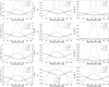 |
Fig. 7 Total planetary flux Fp (in W m−3) and the star-planet contrast C, the degree of polarization Pp of the spatially resolved planet, and Pu, the degree of polarization of the star and the spatially unresolved planet, all for a Current Venus model planet (Phase 4) as functions of the planet’s orbital phase for four mutual inclination angles im and four wavelengths λ: 0.5 µm (row 1); 1.0 µm (row 2); 1.5 µm (row 3); and 2.0 µm (row 4). The longitude of the ascending node of the planetary orbit, Ω, is 205°. |
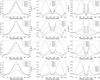 |
Fig. 8 Similar to Fig. 7, except for the model planets in the four evolutionary phases, Ω = 0°, and im = 80° (thus for an edge–on orbit, i = 90°): Phase 1 (Current Earth), Phase 2 (Thin cloud Venus), Phase 3 (Thick cloud Venus), Phase 4 (Current Venus). The wavelengths λ are as before: 0.5 µm (row 1), 1.0 µm (row 2), 1.5 µm (row 3), and 2.0 µm (row 4). |
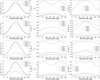 |
Fig. 9 Similar to Fig. 8 except for the most probable, stable orbit around Alpha Centauri A, i.e. for Ω = 205° and im= 35° (Quarles & Lissauer 2016). The wavelengths are as before: 0.5 µm (row 1), 1.0 µm (row 2); 1.5 µm (row 3), and 2.0 µm (row 4). |
3.3 Evolutionary phases across α and λ
In Fig. 10, we show which evolutionary phase has the highest values of |Pp| across all phase angles α and wavelengths λ. We find that |Pp| of the Phase 1 planet (Current Earth) dominates between 30° and 150°, and mostly for λ < 1.0 µm. In particular, around α = 40° and up to λ = 2.0 µm, the polarization signal of the rainbow produced by the large water cloud particles is about 0.1 (see the bottom plot of Fig. 10). For λ > 1.0 µm, the Phase 2 planet (Thin cloud Venus) shows the strongest polarization due to the Rayleigh scattering by the small H2O cloud particles, as can clearly be seen in the bottom plot. The small patches where the strongest polarization signal is from the Thick cloud Venus (Phase 3), for example near α = 20° and λ < 1.0 µm, or from the Current Venus (Phase 4) are due to the single-scattering polarization features of the H2SO4 cloud particles, as can be seen in Fig. 2.
The accessible phase-angle range for direct observations of such exoplanets obviously depends on the actual orientation of the planetary orbits and cannot be optimized by the observer. Precisely because of that, Fig. 10 clearly indicates that measurements should be performed across a broad wavelength range, including wavelengths below 1 µm, to allow us to distinguish between Earth-like and Venus-like planets in various evolutionary phases.
4 Summary and conclusions
We presented the total flux and linear polarization of starlight that is reflected by model planets of various atmospheric types to investigate whether different phases in the evolution of planets like the Earth and Venus can be distinguished from each other. We have used four planet models to represent possible evolutionary phases. Phase 1 (Current Earth) has an Earth-like atmosphere and liquid water clouds; Phase 2 (Thin cloud Venus) has a Venus-like CO2 atmosphere and thin water clouds; Phase 3 (Thick cloud Venus) has a Venus-like CO2 atmosphere and thick sulphuric acid solution clouds; and Phase 4 (Current Venus) has a CO2 atmosphere and thin sulphuric acid solution clouds. We computed the total flux and polarization signals specifically for model planets orbiting our neighboring solar-type star Alpha Centauri A using predicted stable orbits (Quarles & Lissauer 2016) in its habitable zone.
We computed the reflected starlight for wavelengths λ ranging from 0.3 to 2.5 µm and for planetary phase angles α from 0° to 180°. We not only present the fluxes and polarization of spatially resolved model planets (thus without background starlight), but also those of spatially unresolved planets; that is, the combined signal of the planet and the star. For the latter cases, we also computed the planet-star contrast C as a function of α and λ to determine what would technically be required to detect the planetary signals upon the background starlight.
The range of planetary phase angles α at which a planet can be observed (spatially resolved or unresolved) depends on the inclination of the planetary orbit with respect to the observer. We have specifically studied the reflected light signals of planets orbiting solar-type star Alpha Centauri A. This star is part of a double star system with solar-type star Alpha Centauri B. The distance between the two stars varies from 35.6 to 11.2 AU (M-dwarf Alpha Centauri C or Proxima Centauri orbits the pair at a distance of about 13 000 AU). Dynamical computations (Quarles & Lissauer 2016) predict stable planetary orbits around Alpha Centauri A in a narrow range of mutual inclination angles im between the orbital planes of the two stars and that of the planet. In particular, the most stable orbit has im = 35°, which provides an α range from 60° to 120°. We find that with this orbital geometry the degree of polarization of the planet would be largest for the Current Earth (Phase 1) across the visible (λ < 1.0 µm) due to Rayleigh scattering by the gas above the clouds. At near infrared wavelengths (1.0 µm < λ < 2.5 µm), the polarization of the Thin cloud Venus (Phase 2) is highest, because this planet has small cloud droplets that scatter as Rayleigh scatterers at the longer wavelengths.
The well-known advantage of measuring the degree of polarization for the characterization of (exo)planets is that the angular features in the signal of the planet as a whole are similar to the angular features in the light that has been singly scattered by the gas molecules and cloud particles, which are very sensitive to the microphysical properties (such as the size distribution, composition, shape) of the scattering molecules and cloud particles and to the atmosphere’s macrophysical properties (such as cloud altitude and thickness). The reflected total flux is much less sensitive to the atmospheric properties than the degree and direction of polarization (see e.g. Hansen & Travis 1974, for several examples). Indeed, the variations of the planetary flux Fp along a planet’s orbit appear to be mostly due to the change of the fraction of the planetary disk that is illuminated and visible to the observer. They provide limited information on the planet’s atmospheric characteristics, especially if one takes into account that with real observations, the planet radius will be unknown unless the planet happens to transit its star. The variation of the planetary flux Fp with phase angle α and wavelength λ is similar that of planet-star contrast C, which is the ratio of Fp to the stellar flux Fs. For a Venus-like planet orbiting Alpha Centauri A, C is on the order of 10−9.
Our numerical simulations show that variations in Pp, the degree of polarization of the spatially resolved planets (thus without any starlight), with α combined with variations with λ, could be used to distinguish the planetary evolutionary phases explored in this paper:
Phase 1 planets (Current Earth) show strong positive (perpendicular to the reference plane through the star, planet, and observer) polarization around α = 40° due to scattering by large water cloud droplets (the rainbow) and also higher polarization for λ < 0.5 µm and α ≈ 90° due to Rayleigh scattering by the gas above the clouds.
Phase 2 planets (Thin cloud Venus) polarize light negatively (parallel to the reference plane) across most phase angles and at visible wavelengths. At near-infrared wavelengths, they have strong positive polarization around α = 90° due to Rayleigh scattering by the small cloud droplets, and a ‘bridge’ of higher polarization from the Rayleigh maximum to the rainbow angle (α ≈ 40°) with decreasing λ.
Phase 3 planets (Thick cloud Venus) have predominantly negative polarization from the visible to the near-infrared, with small regions of positive polarization for λ < 1.0 µm and for 20° ≤ α ≤ 30° that are characteristic of the 75% H2SO4 cloud particles with reff = 2.0 µm.
Phase 4 planets (Current Venus) yield similar polarization patterns to the Phase 3 planets, except with more prominent negative polarization for 10° ≤ α ≤ 30° and for 0.5 µm ≤ λ ≤ 2 µm. Rayleigh scattering by the small cloud particles produces a maximum of positive polarization around α = 90° and for λ > 2 µm.
Our simulations of the planetary polarization Pp do not include any background starlight, and can thus reach several percent to even 20% for the ‘Current Earth’ (Phase 1) planet in an edge-on orbit (Fig. 8). Whether or not such polarization variations could be measured depends strongly on the techniques used to suppress the light of the parent star. If the background of the planet signal contains a fraction x of the flux of the star, the degree of polarization of the light gathered by the detector pixel that contains the planet will equal (C/(C + x))Pp ≈ (C/x)Pp with C the contrast between the total fluxes of the planet and the star (Eq. (9)). For a Venus-like planet orbiting Alpha Centauri A, C is on the order of 10−9, and thus x should be as small as 10−4 to obtain a polarization signal on the order of 10−6, assuming Pp is about 0.1. Not only excellent direct starlight suppression techniques, but also a very high spatial resolution would help to decrease x.
Our simulations further show that temporal variations in the total flux Fu of Alpha Centauri A with a spatially unresolved terrestrial-type planet orbiting in its habitable zone would be less than 10−12 Wms−1. The degree of polarization Pu of the combined star and planet signals would show variations smaller than 0.05 ppb. To identify this planetary flux on top of the stellar flux, a very-high-sensitivity instrument would be required, and an even higher sensitivity would be required to subsequently characterize the planetary atmosphere. We remind the reader that the orbital period of such a planet, and with that the period of the signal variation and presumably the stability requirements of an instrument, would be about 0.76 yr. Bailey et al. (2018) computed the polarization signal of spatially unresolved, hot, cloudy, Jupiter-like planet HD 189733b to be ~20 ppm. Because of their large size, Jupiter-like planets, and in particular those in close-in orbits that receive large stellar fluxes, would clearly be less challenging observing targets than terrestrial-type planets.
The HARPS instrument on ESO’s 3.6 m telescope includes polarimetric observations with a polarimetric sensitivity of 10−5 (Snik et al. 2011). PlanetPol on the 4.2 m William Herschel Telescope (WHT) on La Palma achieved a sensitivity-to-fractional-linear-polarization (the ratio of linearly polarized flux to the total flux) of 10−6. While PlanetPol did not succeed in detecting exoplanets, it did provide upper limits on the albedos of a number of exoplanets (Lucas et al. 2009). The Extreme Polarimeter (ExPo), which was also mounted on the WHT, was designed to target young stars embedded in protoplanetary disks and evolved stars surrounded by dusty envelopes, with a polarimetric sensitivity better than 10−4 (Rodenhuis et al. 2012). The HIPPI-2 instrument uses repeated observations of bright stars in the SDSS g band for achieving better than 3.5 ppm accuracy on the 3.9 m Anglo-Australian Telescope and better than 11 ppm on the 60 cm Western Sydney University telescope (Bailey et al. 2020). The POLLUX instrument on the LUVOIR space telescope concept aims at high-resolution (R ~ 120 000) spectropolarimetric observations across ultraviolet and visible wavelengths (100–400 nm) to characterize atmospheres of terrestrial-type exoplanets (LUVOIR Team 2019; Rossi et al. 2023). The EPICS instrument planned to be mounted on the Extremely large telescope (ELT), is designed to achieve a contrast of 10−10 depending the angular separation of the objects (Kasper et al. 2010).
In our simulations, we neglected absorption by atmospheric gases. Including such absorption would yield lower total fluxes in specific spectral regions, depending on the type and amount of absorbing gas, its vertical distribution, and on the altitude and microphysical properties of the clouds and hazes. Including absorption by atmospheric gases could increase or decrease the degree of polarization, depending on the amount and vertical distribution of the absorbing gas and on the microphysical properties of the scattering particles at various altitudes (see e.g. Trees & Stam 2022; Stam 2008, for examples of polarization spectra of Earth-like planets). While measuring total and polarized fluxes of reflected starlight across gaseous absorption bands is of obvious interest for the characterization of planets and their atmospheres, the small numbers of photons inside gaseous absorption bands would make such observations extremely challenging.
We also neglected any intrinsic polarization of Alpha Cen-tauri A. Measurements of the degree of linear polarization of FKG stars indicate that active stars such as Alpha Centauri A have a typical mean polarization of 28.5 ± 2.2 ppm (Cotton et al. 2017). This could add to the challenges in distinguishing the degree of polarization of the planet from that of the star if the planet is spatially unresolved, although the phase-angle variation of the planetary signal and the direction of polarization of the planet signal (that is usually either perpendicular or parallel to the plane through the star, the planet, and the observer) could be helpful provided of course that the instrument that is used for the observations has the capability to measure the extremely small variations in the signal as the planet orbits its star (on the order of 10−9).
State-of-the-art instruments with sensitivity to polarization signals down to 10−6 (1000 ppb) are still a few orders of magnitude away from detecting variations in polarization signals from spatially unresolved exo-Earths or exo-Venuses around nearby solar-type stars such as Alpha Centauri A. To be able to distinguish between the different planetary evolutionary phases explored in this paper for example between water clouds or sulphuric acid clouds, variations on the order of 10−9 and hence significant improvements in sensitivity would be needed if the planets were spatially unresolved. The variation in the degree of polarization of spatially resolved planets along their orbital phase should be detectable by instruments capable of achieving star-planet contrasts of 10−9 and that would allow us to distinguish between water clouds and sulphuric acid clouds. Current high-contrast imaging instruments manage to directly image self-luminous objects such as young exoplanets and brown dwarfs in near infrared (NIR) total fluxes at contrasts of 10−2–10−6 (Bowler 2016; Nielsen et al. 2019; Langlois et al. 2021; van Holstein 2021). Furthermore, instruments such as EPICS on ELT and concepts for instruments on future space observatories such as HabEx (Gaudi et al. 2020) and LUVOIR (LUVOIR Team 2019) hold promise for attaining contrasts of ~10−10. Reaching such extreme contrasts would make it possible to directly detect terrestrial-type planets and to use polarimetry to differentiate between exo-Earths and exo-Venuses.
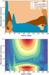 |
Fig. 10 Contour maps showing the planetary models with largest absolute degree of polarization as a function of α and wavelengths λ. Top: the planet models that yield the largest absolute degree of polarization |Pp| over all phase angles α and λ: phase 1 – current Earth (blue); phase 2 – thin cloud Venus (light orange); phase 3 – thick cloud Venus (dark orange); and phase 4 – current Venus (brown). Bottom: the maximum values of |Pp| of the four model planets as functions of α and λ. |
Acknowledgements
This work was supported by the Netherlands Organisation for Scientific Research (NWO) through the User Support Programme Space Research, project number ALW GO 15–37. We thank the referee for the valuable feedback that improved this paper.
References
- Bailey, J. 2007, Astrobiology, 7, 320 [NASA ADS] [CrossRef] [Google Scholar]
- Bailey, J., Kedziora-Chudczer, L., & Bott, K. 2018, MNRAS, 480, 1613 [NASA ADS] [CrossRef] [Google Scholar]
- Bailey, J., Cotton, D.V., Kedziora-Chudczer, L., De Horta, A., & Maybour, D. 2020, PASA, 37, e004 [NASA ADS] [CrossRef] [Google Scholar]
- Bowler, B.P. 2016, PASP, 128, 102001 [NASA ADS] [CrossRef] [Google Scholar]
- Bullock, M.A., & Grinspoon, D.H. 2001, Icarus, 150, 19 [NASA ADS] [CrossRef] [Google Scholar]
- Cotton, D.V., Marshall, J.P., Bailey, J., et al. 2017, MNRAS, 467, 873 [NASA ADS] [Google Scholar]
- de Haan, J.F., Bosma, P., & Hovenier, J. 1987, A&A, 183, 371 [NASA ADS] [Google Scholar]
- De Rooij, W., & Van der Stap, C. 1984, A&A, 131, 237 [NASA ADS] [Google Scholar]
- Donahue, T., Hoffman, J., Hodges, R., & Watson, A. 1982, Science, 216, 630 [NASA ADS] [CrossRef] [Google Scholar]
- García-Muñoz, A., Pérez-Hoyos, S., & Sánchez-Lavega, A. 2014, A&A, 566, L1 [NASA ADS] [CrossRef] [EDP Sciences] [Google Scholar]
- Gaudi, B.S., Seager, S., Mennesson, B., et al. 2020, ArXiv preprint [arXiv: 2001.06683] [Google Scholar]
- Hale, G.M., & Querry, M.R. 1973, Appl. Opt., 12, 555 [NASA ADS] [CrossRef] [Google Scholar]
- Hansen, J.E., & Hovenier, J. 1974, J. Atmos. Sci., 31, 1137 [NASA ADS] [CrossRef] [Google Scholar]
- Hansen, J.E., & Travis, L.D. 1974, Space Sci. Rev., 16, 527 [NASA ADS] [CrossRef] [Google Scholar]
- Jordan, S., Rimmer, P.B., Shorttle, O., & Constantinou, T. 2021, ApJ, 922, 44 [NASA ADS] [CrossRef] [Google Scholar]
- Kane, S.R., Vervoort, P., Horner, J., & Pozuelos, F.J. 2020, Planet. Sci. J., 1, 42 [NASA ADS] [CrossRef] [Google Scholar]
- Karalidi, T., Stam, D., & Hovenier, J. 2011, A&A, 530, A69 [NASA ADS] [CrossRef] [EDP Sciences] [Google Scholar]
- Karalidi, T., Stam, D., & Hovenier, J. 2012, A&A, 548, A90 [NASA ADS] [CrossRef] [EDP Sciences] [Google Scholar]
- Kasper, M., Beuzit, J.-L., Verinaud, C., et al. 2010, SPIE, 7735, 948 [Google Scholar]
- Kasting, J.F. 1988, Icarus, 74, 472 [NASA ADS] [CrossRef] [Google Scholar]
- Keller, C.U., Schmid, H.M., Venema, L.B., et al. 2010, SPIE, 7735, 77356G [NASA ADS] [Google Scholar]
- Kemp, J.C., Henson, G., Steiner, C., & Powell, E. 1987, Nature, 326, 270 [NASA ADS] [CrossRef] [Google Scholar]
- Kliore, A.J., Moroz, V.I., & Keating, G. 1985, The Venus International Reference Atmosphere (Amsterdam: Elsevier) [Google Scholar]
- Knollenberg, R.G., & Hunten, D.M. 1980, J. Geophys. Res. Space Phys., 85, 8039 [NASA ADS] [CrossRef] [Google Scholar]
- Langlois, M., Gratton, R., Lagrange, A.-M., et al. 2021, A&A, 651, A71 [NASA ADS] [CrossRef] [EDP Sciences] [Google Scholar]
- Laven, P. 2008, Appl. Opt., 47, H133 [NASA ADS] [CrossRef] [Google Scholar]
- Lincowski, A.P., Meadows, V.S., Crisp, D., et al. 2018, ApJ, 867, 76 [NASA ADS] [CrossRef] [Google Scholar]
- Lucas, P.W., Hough, J.H., Bailey, J.A., et al. 2009, MNRAS, 393, 229 [NASA ADS] [CrossRef] [Google Scholar]
- Lustig-Yaeger, J., Meadows, V.S., & Lincowski, A.P. 2019a, AJ, 158, 27 [NASA ADS] [CrossRef] [Google Scholar]
- Lustig-Yaeger, J., Meadows, V.S., & Lincowski, A.P. 2019b, ApJ, 887, L11 [NASA ADS] [CrossRef] [Google Scholar]
- LUVOIR Team 2019, ArXiv preprint [arXiv:1912.06219] [Google Scholar]
- Markiewicz, W.J., Petrova, E., Shalygina, O., et al. 2014, Icarus, 234, 200 [NASA ADS] [CrossRef] [Google Scholar]
- Markiewicz, W.J., Petrova, E.V., & Shalygina, O.S. 2018, Icarus, 299, 272 [NASA ADS] [CrossRef] [Google Scholar]
- Nielsen, E.L., De Rosa, R.J., Macintosh, B., et al. 2019, AJ, 158, 13 [NASA ADS] [CrossRef] [Google Scholar]
- Palmer, K.F., & Williams, D. 1975, Appl. Opt., 14, 208 [NASA ADS] [CrossRef] [Google Scholar]
- Quarles, B., & Lissauer, J.J. 2016, AJ, 151, 111 [NASA ADS] [CrossRef] [Google Scholar]
- Ragent, B., Esposito, L., Tomasko, M., et al. 1985, Adv. Space Res., 5, 85 [NASA ADS] [CrossRef] [Google Scholar]
- Rodenhuis, M., Canovas, H., Jeffers, S.V., et al. 2012, SPIE Conf. Ser., 8446, 84469I [NASA ADS] [Google Scholar]
- Rossi, L., & Stam, D.M. 2018, A&A, 616, A117 [NASA ADS] [CrossRef] [EDP Sciences] [Google Scholar]
- Rossi, L., Marcq, E., Montmessin, F., et al. 2015, Planet. Space Sci., 113, 159 [Google Scholar]
- Rossi, L., Berzosa-Molina, J., & Stam, D.M. 2018, A&A, 616, A147 [NASA ADS] [CrossRef] [EDP Sciences] [Google Scholar]
- Rossi, L., Berzosa-Molina, J., Desert, J.-M., et al. 2023, Exp. Astron., in press [Google Scholar]
- Russell, E.E., Brown, F.G., Chandos, R.A., et al. 1992, Space Sci. Rev., 60, 531 [NASA ADS] [Google Scholar]
- Snik, F., Kochukhov, O., Piskunov, N., et al. 2011, Solar Polarization 6, Proceedings of a conference held in Maui, Hawaii, USA on May 30 to June 4, 2010, eds. J.R. Kuhn, D.M. Harrington, H. Lin, et al. (San Francisco: Astronomical Society of the Pacific), 237 [Google Scholar]
- Stam, D. 2008, A&A, 482, 989 [NASA ADS] [CrossRef] [EDP Sciences] [Google Scholar]
- Stam, D., & Hovenier, J. 2005, A&A, 444, 275 [NASA ADS] [CrossRef] [EDP Sciences] [Google Scholar]
- Titov, D.V., Ignatiev, N.I., McGouldrick, K., Wilquet, V., & Wilson, C.F. 2018, Space Sci. Rev., 214, 1 [NASA ADS] [CrossRef] [Google Scholar]
- Trees, V.J.H., & Stam, D.M. 2022, A&A, 664, A172 [NASA ADS] [CrossRef] [EDP Sciences] [Google Scholar]
- Tselioudis, G., Rossow, W.B., & Jakob, C., et al. 2021, Journal of Climate, 34, 7311 [Google Scholar]
- Turbet, M., Bolmont, E., Chaverot, G., et al. 2021, Nature, 598, 276 [CrossRef] [Google Scholar]
- van Holstein, R. 2021, PhD thesis, Leiden University, The Netherlands [Google Scholar]
- Way, M.J., & Del Genio, A.D. 2020, J. Geophys. Res. Planets, 125, e2019JE006276 [CrossRef] [Google Scholar]
All Tables
Values of the parameters describing the planetary system of Alpha Centauri A used in our numerical modeling.
Model planets’ geometric albedos AG for the four evolutionary phases at four wavelengths.
All Figures
|
Fig. 1 Four evolutionary phases of the model planets (Bullock & Grinspoon 2001). In Phases 1 and 2, the clouds consist of liquid water droplets, and in Phases 3 and 4, they consist of liquid sulfuric acid solution droplets. The cloud optical thickness is indicated by bc and the cloud particle effective radius by reff. For the effective variance υeff of the size distributions in Phases 1–3, we used 0.1, and for Phase 4 we used υeff = 0.07. |
| In the text | |
|
Fig. 2 Total flux and degree of polarization of incident unpolarized light that has been singly scattered by four different types of cloud particles, as functions of the phase angle α and the wavelength λ. Left column: total flux or phase function (single-scattering matrix element P11). Right column: degree of polarization (−P21/P11). First row: H2O particles with reff = 10 µm and υeff = 0.1 (belonging to the Phase 1 model planet: ‘Current Earth’). Second row: H2O particles with reff = 0.5 µm and υeff = 0.1 (Phase 2: ‘Thin cloud Venus’). Third row: 75% H2SO4 particles with reff = 2.0 µm and υeff = 0.1 (Phase 3: ‘Thick cloud Venus’). Fourth row: 75% H2SO4 particles with reff = 1.05 µm and υeff = 0.07 (Phase 4: ‘Current Venus’). |
| In the text | |
|
Fig. 3 Total flux (or phase function) and degree of polarization of incident unpolarized starlight that is reflected by the model planets in the 4 evolutionary phases as functions of α and λ. Left column: the total flux (or phase function). Right column: degree of polarization. First row: phase 1 (‘Current Earth’). Second row: phase 2 (‘Thin cloud Venus’). Third row: phase 3 (‘Thick cloud Venus’). Fourth row: phase 4 (‘Current Venus’). The phase functions are normalized such that at α = 0°, and they equal the planet’s geometric albedo AG. |
| In the text | |
|
Fig. 4 Planets’ geometric albedo’s AG as functions of the wavelength λ for the four evolutionary phases. |
| In the text | |
|
Fig. 5 Sketch of geometries within the Alpha Centauri system: the orbital plane of the stars Alpha Centauri A and В is inclined by about 80° with respect to the observer on Earth. Our model planet (the blue dot) orbits Alpha Centauri A. In this sketch, the line of nodes of the planet’s orbit was chosen to coincide with that of the stellar orbits. The inclination angle im of the planet’s orbit with respect to the stellar orbital plane is 45°, and the inclination angle of the planet’s orbit with respect to the observer is 80° − 45° = 35°. The phase angles of the planet in this sketch would range from 90° − 35° = 55° to 90° + 35° = 125°. |
| In the text | |
|
Fig. 6 Variation of the planet’s phase angle α along the planet’s orbit around Alpha Centauri A for different mutual inclination angles im of the planetary orbit with respect to the orbital plane of the two stars. Top: Ω, the longitude of the ascending node of the planet’s orbit, is 0°. For im = −10°, the planet is then in a face-on orbit (i = 0°), while for im = 80°, it is in an edge-on orbit (i = 90°). Bottom: Ω = 205°, and the planetary orbit is aligned with the node of the stellar orbital plane. |
| In the text | |
|
Fig. 7 Total planetary flux Fp (in W m−3) and the star-planet contrast C, the degree of polarization Pp of the spatially resolved planet, and Pu, the degree of polarization of the star and the spatially unresolved planet, all for a Current Venus model planet (Phase 4) as functions of the planet’s orbital phase for four mutual inclination angles im and four wavelengths λ: 0.5 µm (row 1); 1.0 µm (row 2); 1.5 µm (row 3); and 2.0 µm (row 4). The longitude of the ascending node of the planetary orbit, Ω, is 205°. |
| In the text | |
|
Fig. 8 Similar to Fig. 7, except for the model planets in the four evolutionary phases, Ω = 0°, and im = 80° (thus for an edge–on orbit, i = 90°): Phase 1 (Current Earth), Phase 2 (Thin cloud Venus), Phase 3 (Thick cloud Venus), Phase 4 (Current Venus). The wavelengths λ are as before: 0.5 µm (row 1), 1.0 µm (row 2), 1.5 µm (row 3), and 2.0 µm (row 4). |
| In the text | |
|
Fig. 9 Similar to Fig. 8 except for the most probable, stable orbit around Alpha Centauri A, i.e. for Ω = 205° and im= 35° (Quarles & Lissauer 2016). The wavelengths are as before: 0.5 µm (row 1), 1.0 µm (row 2); 1.5 µm (row 3), and 2.0 µm (row 4). |
| In the text | |
|
Fig. 10 Contour maps showing the planetary models with largest absolute degree of polarization as a function of α and wavelengths λ. Top: the planet models that yield the largest absolute degree of polarization |Pp| over all phase angles α and λ: phase 1 – current Earth (blue); phase 2 – thin cloud Venus (light orange); phase 3 – thick cloud Venus (dark orange); and phase 4 – current Venus (brown). Bottom: the maximum values of |Pp| of the four model planets as functions of α and λ. |
| In the text | |
Current usage metrics show cumulative count of Article Views (full-text article views including HTML views, PDF and ePub downloads, according to the available data) and Abstracts Views on Vision4Press platform.
Data correspond to usage on the plateform after 2015. The current usage metrics is available 48-96 hours after online publication and is updated daily on week days.
Initial download of the metrics may take a while.