| Issue |
A&A
Volume 655, November 2021
|
|
|---|---|---|
| Article Number | A35 | |
| Number of page(s) | 16 | |
| Section | Stellar atmospheres | |
| DOI | https://doi.org/10.1051/0004-6361/202039707 | |
| Published online | 09 November 2021 | |
Spherically symmetric model atmospheres using approximate lambda operators
V. Static inhomogeneous atmospheres of hot dwarf stars
Astronomical Institute of the Czech Academy of Sciences,
Fričova 298,
251 65
Ondřejov,
Czech Republic
email: kubat@sunstel.asu.cas.cz
Received:
18
October
2020
Accepted:
7
June
2021
Context. Clumping is a common property of stellar winds and is being incorporated to a solution of the radiative transfer equation coupled with kinetic equilibrium equations. However, in static hot model atmospheres, clumping and its influence on the temperature and density structures have not been considered and analysed at all to date. This is in spite of the fact that clumping can influence the interpretation of resulting spectra, as many inhomogeneities can appear there; for example, as a result of turbulent motions.
Aims. We aim to investigate the effects of clumping on atmospheric structure for the special case of a static, spherically symmetric atmosphere assuming microclumping and a 1D geometry.
Methods. Static, spherically symmetric, non-LTE (local thermodynamic equilibrium) model atmospheres were calculated using the recent version of our code, which includes optically thin clumping. The matter is assumed to consist of dense clumps and a void interclump medium. Clumping is considered by means of clumping and volume filling factors, assuming all clumps are optically thin. Enhanced opacity and emissivity in clumps are multiplied by a volume filling factor to obtain their mean values. These mean values are used in the radiative transfer equation. Equations of kinetic equilibrium and the thermal balance equation use clump values of densities. Equations of hydrostatic and radiative equilibrium use mean values of densities.
Results. The atmospheric structure was calculated for selected stellar parameters. Moderate differences were found in temperature structure. However, clumping causes enhanced continuum radiation for the Lyman-line spectral region, while radiation in other parts of the spectrum is lower, depending on the adopted model. The atomic level departure coefficients are influenced by clumping as well.
Key words: stars: atmospheres / radiative transfer / atomic processes / opacity / methods: numerical
© ESO 2021
1 Introduction
The calculation of 1D model atmospheres has reached an extremely high level of sophistication, as it is now possible to calculate NLTE (non-LTE; LTE means local thermodynamic equilibrium) model atmospheres for different chemical compositions, with a lot of detail regarding line and continuum formation, and, most importantly, with the inclusion of NLTE line blanketing almost for all stellar types (see Hubeny & Mihalas 2015). One of the most elaborate computer codes used for the calculation of NLTE, plane-parallel, horizontally homogeneous model atmospheres is TLUSTY (see Hubeny 2019 and references therein). However, all physical processes that lack the plane-parallel or spherical symmetry have to be included in an approximate way. As an example, convection is formed by a complex spectrum of turbulent motions. However, it is usually treated using the mixing-length approximation. Besides turbulent motions causing convection, it is the possible presence of simpler atmospheric inhomogeneities, usually referred to as clumping, that are treated approximately as well.
Strictly speaking, as the 1D model atmospheres are only homogeneous horizontally, they are in fact inhomogeneous since the physical quantities vary with the depth coordinate (z or r), but this is not the meaning of an ’inhomogeneous atmosphere’ in this paper. Historically, the term ‘inhomogeneous stellar atmosphere’ was also used to emphasise the horizontal variability of quantities (e.g. Wilson 1968, 1969). Clumping generally refers to the true inhomogeneity in all three dimensions, which is sometimes referred to as the ‘stochastic medium’ (e.g. Pomraning 1991; Gu et al. 1995).
Clumping is a property of a stellar atmosphere, which is in principle 3D. To describe its effects correctly, it has to be properly included using a 3D model atmosphere. 3D stellar atmospheric modelling is being done for solar and cool star atmospheres. Several powerful hydrodynamic codes exist to perform this task (e.g. Stein & Nordlund 1998; Nordlund & Stein 2009; Freytag et al. 2012, 2019; Trampedach et al. 2013; Ludwig & Steffen 2016). For radiation-matter interaction, the assumption of the LTE is being used. On top of these models, a NLTE 3D line-formation problem for particular ions is being solved, mostly considering corresponding chemical elements as trace ones (e.g. Leenaarts & Carlsson 2009; Steffen et al. 2015; Bjørgen & Leenaarts 2017; Nordlander et al. 2017; Bergemann et al. 2019, and references therein as recent examples of calculations, or Asplund & Lind 2010 for a review).
For the construction of hot star model atmospheres, the assumption of LTE is not acceptable at all (see discussions in Hubeny & Mihalas 2015). Hydrodynamics calculations in combination with NLTE are extremely demanding, and as such full 3D treatment is still beyond the capabilities of contemporary computers, although recent progress has been made (Hennicker et al. 2018, 2020; Fišák et al. 2019). Therefore, 3D NLTE treatment of clumping in hot stars is only done in special cases; for example, for radiative transfer in selected resonance lines (e.g. Sundqvist et al. 2010, 2011; Šurlan et al. 2012, 2013).
It is widely accepted that clumping in line-driven stellar winds is caused by the line-driven instability (often referred to as LDI). Since its suggestion by Lucy & Solomon (1970), subsequent analyses and modelling proved its existence in 1D hydrodynamic wind models (see Owocki et al. 1988 and references therein). Hydrodynamical simulations of line-driven instabilities in stellar winds were recently extended to 2D (see Sundqvist et al. 2018; Owocki & Sundqvist 2018, and references therein).
However, the existence of a sub-photospheric convection in hot stars (Cantiello et al. 2009; Grassitelli et al. 2016) and other 3Deffects inmassive star envelopes (Jiang et al. 2015, 2018 and references therein) offer another possibility for the creation of clumps, which is not limited to a presence of a line-driven stellar wind and an inherent instability.
The majority of wind modelling codes consider clumping in a 1D approximation, which means that severe simplifications have to be employed. The assumption of a 1D spherically symmetric flow is employed in the NLTE wind modelling codes, which solve the NLTE equations (i.e. radiative transfer and kinetic equilibrium equations) and optionally an equation for temperature determination (radiative equilibrium or thermal balance equations) for a given density and velocity structure. To our knowledge, three such codes exist, namely CMFGEN (e.g. Hillier & Miller 1998), PoWR (e.g. Hamann & Gräfener 2004), and FASTWIND (e.g. Santolaya-Rey et al. 1997; Puls et al. 2005). These codes consider clumping asa simple correction of the existing smooth hydrodynamic structure using the clumping factor or its inverse (the volume filling factor), and solve the NLTE line formation problem in such a modified atmosphere without changing the mean atmospheric structure. Many clumped wind models have been calculated in such way.
The actual value of the adopted clumping factor is a matter of discussion. Sometimes it is necessary to use very high clumping factors (e.g. ~50 for WR stars, Sander & Vink 2020), but this necessity is probably caused by the fact that these clumping factors refer to microclumping. If macroclumping (clumps are allowed to be optically thick) is taken into account, much smaller values are sufficient (Kubátová et al. 2015).
Attempts to include the influence of clumping on the mean structure of a 1D stellar atmosphere (mean density, velocity) are not so frequent. Muijres et al. (2011) studied the effect of clumping on mass-loss rate predictions. Wind models with optically thin clumps both in lines and continuum (microclumping) were used in a calculation presented by (Krtička et al. 2018, see also references therein). A method for inclusion of clumping into rate equations for 1D NLTE wind models was developed by Sundqvist et al. (2014) and used by Sundqvist & Puls (2018).
In the past, we developed a static 1D model atmosphere code (Kubát 2003, and references therein) capable of building the structure of either spherically symmetric or plane-parallel NLTE model atmospheres. Given the evidence that clumping in hot star atmospheres can be caused by processes not connected with the existence of stellar winds (e.g. sub-photospheric convection), we decided to include an approximate description of atmospheric inhomogeneities to 1D static model atmosphere construction, which has not been done before, and to study the consequences of such an approach.
2 Description of clumping
Stellar atmospheres are very often modelled using a simplified picture. The most commonly used model is the atmosphere consisting of horizontally homogeneous layers, which may be parallel layers for plane-parallel atmospheres or concentric shells for spherically symmetric atmospheres. This offers a possibility to use the advantage of a 1D geometry description. However, as direct observations of selected stars show surface structures, the assumption of horizontally homogeneous atmospheres is questioned. It is highly probable that no stars have strictly horizontally homogeneous atmospheres and their inhomogeneity is significantly more complicated. Some parts of the atmosphere can violate the assumption of horizontal homogeneity having either higher or lower density than the values predicted by a horizontally homogeneous model, with a variable size of these regions. Since the details of stellar atmosphere inhomogeneities and process of their formation are vastly unknown and their description involving the full spectrum of possible shapes is far complicated, a simplified description of inhomogeneity is necessary. In 1D model atmospheres this is conveniently done using clumping or volume filling factors. We describe the 1D model of clumping applied in this paper in a more detail.
2.1 1D treatment of clumping
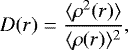
The atmosphere is assumed to consist of clumps. To simplify the problem, the space between clumps is assumed to be void. Clumps are assumed to be smaller than the photon mean free path, and this assumption is often referred to as optically thin clumping (Hamann & Koesterke 1998) or microclumping (Oskinova et al. 2007). Clumping is usually characterised by a clumping factor (we denote this quantity as D in this paper), a ratio of a mean-square deviation of the density and the mean density squared (see Chandrasekhar & Münch 1952, Eq. (25)), which, for the case of a 1D, spherically symmetric stellar atmosphere, can be written introducing its radius dependence as
 (1)
(1)
or using z instead of r as the independent variable for the case of the plane-parallel atmosphere. Introducing the volume filling factor fvol (r), which describes the fraction of volume filledby clumps at a radius r, we can relate the density in clumps ρcl(r) to the mean density of the atmosphere ρmean(r) as
 (2)
(2)
Inserting this equation into (1), we obtain (see also Sundqvist & Puls 2018)
 (3)
(3)
In other words, ρmean is the density as it would be in a medium without clumps (in a horizontally homogeneous atmosphere). This quantity is also being referred to as the smooth atmosphere (wind) density (ρsm = ρmean). Equation (3) is valid also for all variables describing number densities. For example, the ratio of the electron number density inside clumps  and the mean electron number density
  is also D(r).
It has to be noted that the 1D description of clumps may be more detailed. If the assumption of optically thin clumping is violated, then more parameters are necessary to describe properties of a clumped medium. The quantity porosity length h describing the photon mean free path between clumps (which may be optically thick) has to be introduced to the clump description (see Feldmeier et al. 2003; Owocki et al. 2004; Sundqvist & Puls 2018). However, the porosity length h is an additional free parameter, and we aim to test basic clumping effects in optically thin (τR ≲ 2∕3) parts of static 1D atmospheres. To avoid using too many free parameters for this purpose, we decided to postpone the more detailed analysis using the porosity length to future, and thus we keep the simpler assumption of optically thin clumping in this paper.
In the following sections, references to equations from Kubát (1996, hereafter Paper II) are made. These equations are denoted as II.x.
2.2 Opacity, emissivity, and scattering
Opacity, emissivity, and scattering coefficients are considered per volume in this paper. Inside clumps, they are evaluated using actual mass and number densities there. The total opacity in clumps χcl is given as a sum of atomic opacities (bound-bound, bound-free, and free-free) and the scattering opacity,
 (4)
(4)
whereas the total emissivity in clump ηcl consists of bound-bound, bound-free, and free-free emissivities, and the following scattering emissivity:
 (5)
(5)
Naturally, the opacity, emissivity, and scattering coefficients in the void interclump medium are zero. To obtain mean values of the coefficients, which are the means over both clumps and void interclump medium, we simply have to multiply the opacity in the clumps by the volume filling factor, namely
 (6)
(6)
According to Eq. (3), the densities in clumps are D times larger than the densities in an atmosphere without clumps (ρcl = Dρsm). As a result, in clumps, all processes whose opacity depends on the first power of density, like all line absorptions and emissions, photoionisation, and scattering on free electrons, have D times largervalues of opacity than in the atmosphere without clumps (e.g. for bound-bound transitions  ). The mean opacity of the medium is obtained as a volume weighted sum of opacities in clumps and in an interclump medium. Consequently, for a void interclump medium the expression for bound-bound opacities simplifies to
  ), and similarly for the bound-bound emissivity
  , bound-free opacity
  , and electron scattering
  . Processes, whose opacity depends on a product of two densities, like free-free transitions or radiative recombination (depend on a product of electron density and ion density), have in clumps D2 larger values of opacity than in the atmosphere without clumps (e.g. for free-free opacity
  ). Consequently, the corresponding mean opacity
  ) and similarly for
  and
and  (see Kubát & Kubátová 2019, Eq. (10)). This also affects other quantities appearing in the radiative transfer equation, such as the optical depth and the source function, whose mean values have more complicated density dependence because they depend on a combination of processes with different clumping dependences.
2.3 Radiative transfer equation
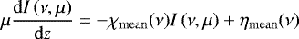
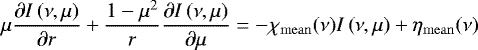
To include the atmospheric inhomogeneities in the 1D case, the planar Eq. (II.1) and the spherically symmetric (II.2) radiative transfer equations have to be modified by using mean values of opacity and emissivity (6), namely
 (7a)
(7a)
for the spherical geometry. Associated moment equations for the mean intensity read
![\begin{equation*}\frac{{\mathrm d}^2\left[{f(\nu) J(\nu)}\right]}{{\mathrm d}\left[{\tau(\nu)}\right]^2} = J(\nu) - S(\nu) \end{equation*}](/articles/aa/full_html/2021/11/aa39707-20/aa39707-20-eq20.png) (8a)
(8a)
for the planar geometry, and
![\begin{equation*}\frac{{\mathrm d}^2\left[{f(\nu) q(\nu) J(\nu)}\right]}{{\mathrm d}\left[{X(\nu)}\right]^2} = \frac{r^4}{q(\nu)} \left[{J(\nu) - S(\nu)}\right] \end{equation*}](/articles/aa/full_html/2021/11/aa39707-20/aa39707-20-eq21.png) (8b)
(8b)
for the spherical geometry; q(ν) is the sphericity factor (Auer 1971) defined by Eq. (II.3), and f(ν) is the variable Eddington factor. Here, the plane-parallel optical depth is
 (9a)
(9a)
the optical-depth-like variable X(ν) used in the spherically symmetric case (different from the one used by Mihalas & Hummer 1974) is
 (9b)
(9b)
and the source function is
 (10)
(10)
2.4 Equations of kinetic (statistical) equilibrium
The equations of kinetic (statistical) equilibrium are evaluated using actual density ρcl in clumps, which means also using the actual electron density  . The equations are then solved for
  , the occupation numbers for matter inside clumps. Values of both collisional and radiative rates are calculated using proper values of densities.
2.5 Structural equations
The structural equations determining the temperature and density structure of the atmosphere are treated using mean values of densities. This is important for the equation of hydrostatic equilibrium and the differential form of the equation of radiative equilibrium.
The basic independent variable of the model is the column mass depth, which is defined as d m = −ρdz for the plane-parallel atmosphere and  for the spherically symmetric atmosphere (R* is the stellar radius, see II.9). For the case of a clumped model atmosphere, we define the column mass depth as
 (11a)
(11a)
for the plane parallel case, and
 (11b)
(11b)
for the spherically symmetric case (ρmean was introduced in Eq. (2)).
2.5.1 Radiative equilibrium
The integral form of the equation of radiative equilibrium expresses the balance between absorbed and emitted radiation energy. Consequently, it remains the same as in the case of homogeneous atmospheres, namely it has the form (II.12), and the opacity and emissivity values in clumps are used:
![\begin{equation*}\int_0^{\infty} \left[{{\chi_{\mathrm{cl}}}^{\mathrm{at}}(\nu) J_{\nu} - {\eta_{\mathrm{cl}}}^{\mathrm{at}}(\nu)}\right] {\mathrm d} \nu = 0, \end{equation*}](/articles/aa/full_html/2021/11/aa39707-20/aa39707-20-eq30.png) (12)
(12)
where Jν is the mean radiation intensity, ν stands for frequency, and  and
and  were introduced in Eq. (4). As the interclump medium is void in our case, the equation of radiative equilibrium has no physical sense there. Taking into account Eq. (6), mean opacity and emissivity values can be used in Eq. (12) as well.
The differential form of the equation of radiative equilibrium (II.19) describes the conservation of the total radiative flux, which flows through both clumps and the interclump medium. Consequently, mean quantities have to be used. We consider its modified form:
![\begin{equation*}H_0 = \int_0^{\infty} \frac{{\rho_{\mathrm{mean}}}}{q(\nu) {{\chi_{\mathrm{mean}}}}(\nu)} \frac{{\mathrm d}\left[{q(\nu) f(\nu) J(\nu)}\right]}{{\mathrm d}m} {\mathrm d}\nu ,\end{equation*}](/articles/aa/full_html/2021/11/aa39707-20/aa39707-20-eq33.png) (13)
(13)
where χmean(ν) is the mean opacity (absorption + scattering), q(ν) is the sphericity factor (see Eq. (8b)) for the spherically symmetric case (for the plane-parallel case we may set q(ν) = 1), f(ν) is the variable Eddington factor, and  for the plane-parallel case and
  for the spherically symmetric case. L* is the stellar luminosity, and Teff is the stellareffective temperature.
2.5.2 Thermal balance
Equations of thermal balance of electrons (see Kubát et al. 1999, hereafter KPP) can replace the integral form of the radiative equilibrium in the outermost layers of the stellar atmospheres, where the bound-bound radiative rates are so strong that they numerically saturate the radiative equilibrium Eq. (12), and their difference is subject to a large numerical error.
Thermal balance equations describe the local balance of thermal energy. Consequently, all number densities in the equations in KPP have to be replaced by their clump values1. Free-free heating and cooling are expressed using equations (KPP.3) and (KPP.4), respectively, where  and
and  . Similarly, for bound-free heating and cooling equations (KPP.5) and (KPP.6), respectively, are used with
  . For collisional heating and cooling, equations (KPP.11) and (KPP.12) are used with the above-mentioned substitutions.
2.5.3 Hydrostatic equilibrium
Using Eq. (11), the equation of hydrostatic equilibrium can be written in the same form as (II.10)
![\begin{equation*}\frac{{\mathrm d}p_g}{{\mathrm d}m} = \frac{G {M_{\ast}}}{{R_{\ast}}^2} - \frac{4 \pi}{c} \int_0^{\infty} \frac{1}{q(\nu)} \frac{{\mathrm d}\left[{q(\nu) f(\nu) J(\nu)}\right]}{{\mathrm d}m} {\mathrm d}\nu, \end{equation*}](/articles/aa/full_html/2021/11/aa39707-20/aa39707-20-eq39.png) (14)
(14)
where pg is the gas pressure, M* is the stellar mass,and c is the light speed. This equation is accompanied by the upper boundary condition (II.11),
![\begin{equation*}\frac{p_1}{m_1} = \frac{G {M_{\ast}}}{{R_{\ast}}^2} - \frac{4 \pi}{c} \left({\frac{r_1}{{R_{\ast}}}}\right)^2 \int_0^{\infty} \frac{\chi_1(\nu)}{\rho_1} \left[{g_1(\nu) J_1(\nu) - H^-(\nu)}\right] {\mathrm d}\nu, \end{equation*}](/articles/aa/full_html/2021/11/aa39707-20/aa39707-20-eq40.png) (15)
(15)
where the index 1 denotes quantities at the uppermost depth point of the model (we set r1 = R* for the plane-parallel case),  (j(ν, μ) is the mean intensity-like Schuster 1905 variable), and H−(ν) is the incident flux. The opacity χ and density ρ are both either clump or mean values, since the clumping factors are cancelled in the fraction.
2.5.4 Clumping at great depths
On average, clumping increases the opacity thanks to the D2 dependence of the free-free absorption coefficient. Consequently, for a fixed column-mass-depth scale m given by Eq. (11), the optical depth of a clumped medium increases for all frequencies. Depending on the clumping factor D, the depth of radiation formation shifts upwards, which affects the temperature structure. At great depths, clumping causes an increase of the Rosseland optical depth τR, temperature follows the gray dependence (e.g. Hubeny & Mihalas 2015, Eq. (17.67)), and it results in some heating there.
There is, of course, a question of whether clumping in our approximation of void interclump medium and optically thin clumping has any physical meaning at significant optical depths (τ ≫ 1). There, the diffusion approximation for radiation is valid, but assuming horizontally homogeneous medium. A void interclump medium means that radiation can propagate without any interaction with matter through these interclump voids, which contradicts radiation diffusion. To avoid these unrealistic effects on the deepest (and optically thick) parts of the atmosphere, we decided to assume no clumping there by setting D = 1 for τR ≳ 2∕3 with gradual transition using linear interpolation in logτR to actual D at τR ~ 0.1.
2.6 Implementation in the code
Our method for calculation of 1D static NLTE model atmospheres and the associated code (Kubát 1994, 1996, 1997b, 2001, 2003) use the accelerated lambda iteration technique in combination with the complete linearisation (multi-dimensional Newton-Raphson) method. The code had to be updated to include clumping as described in this section. Basic changes are described below.
The basic independent variable m (column mass depth) is defined using mean densities after Eq. (11). After the m-scale is set, it is fixed during all calculations. For densities, both values inside clumps (ρcl,  ) and mean values (ρmean,
  ) are stored for each depth point. The relation between ρcl and ρmean is given by Eq. (3), similarly to the electron number density. Alternatively, only one value may be stored and the other recalculated when necessary, but we decided to store both values.
Opacities are first evaluated using actual densities in clumps (ρcl,  , ...). Then, the opacities are divided by the clumping factor (Eq. (6)) to obtain their mean values. Next, the Rosseland and flux mean opacities are calculated. Mean opacities and emissivities (6) are used in the radiative transfer equation to take into account transfer of radiation through a mean medium consisting of both clumps and an interclump medium.
Kinetic equilibrium equations are formulated using number densities (occupation numbers) in clumps. Electron number densities that enter the equations for radiative and collisional rates are clump electron number densities  .
.
The temperature is that of matter in clumps. Two of the temperature determination methods, namely the integral form of radiative equilibrium and the thermal balance method, describe local processes. Opacities calculated from densities in clumps (ρcl,  ) were used. The differential form of radiative equilibrium uses mean values of densities (ρmean), since this equation describes conservation of the radiation flux. Mean densities ρmean are also used in the equation of hydrostatic equilibrium.
Basic input global parameters of calculated model atmospheres.
3 Model calculations
Using our modified code, we calculated several test model sets of static atmospheres. Model atmospheres consist only of hydrogen and helium. Atomic data and model atoms were the same as those we used previously (Kubát 2012). The helium abundance in all models was YHe = nHe∕nH = 0.1, nHe and nH are mean number densities of helium and hydrogen, respectively. Basic global stellar parameters (luminosity L*, radius R*, mass M*, effective temperatureTeff, surface gravity g) of calculated models are listed in Table 1. These parameters were chosen to cover B- and O-type main-sequence stars (O6, O8, B0, B2, B4, and B6 parameters after Harmanec 1988), supplemented by one hot subdwarf model (55-4, parameters as in Krtička et al. 2016). For each set of parameters, models for clumping factors D = 1, 2, 3, 4, 5, 6, 7, 8 were calculated.
We calculated full static spherically symmetric NLTE model atmospheres, meaning solutions for electron density ne, temperature T, radius r, and number densities for all atomic levels ni (i =1, …, L, where L is the total number of atomic levels considered). In the model calculation output, the latter are expressed as products of LTE number densities  (for actual values of temperature and mass density) anddeparture coefficients (b-factors
  ).
).
The depth scale of our models was from m ~ 103 to m ~ 10−8, and in special cases to m ~ 10−9 (in CGS units). We chose the outer boundary at low m (consequently low Rosseland optical depth τR, which is of the same order of magnitude) to ensure that all explicitly considered lines become optically thin within the model. All models were iterated until the relative change for all iterated variables was lower than 10−4.
We encountered convergence problems for high clumping factors for models B2 (see Table 1, to overcome them we set the resonance transitions of helium ions (He I 1s 1S ↔2p1P, He II n = 1 ↔ n = 2) to a detailed radiative balance. To obtain a consistent set of models, we used this detailed radiative balance approximation for all clumping factors for the B2 models.
4 Results
4.1 Temperature structure
The temperature structure shows a temperature rise at lower optical depths, which is typical for H-He NLTE model atmospheres (see Mihalas & Auer 1970, Figs. 1–4). A general trend of ‘shifting the temperature structure outwards’ and lowering the temperature minimum with an increasing clumping factor can be seen in all our model sets (see Figs. 1 and 2). This is caused by increasing free-free opacity with an increasing clumping factor, which shifts the continuum formation region upwards to lower m. The temperature in the outermost atmospheric layers does not change significantly with an increasing clumping factor, especially for hotter atmospheres from our sample. All changes are within ~ 1000 K. The temperatureincrease found by our preliminary calculations (Kubát & Kubátová 2019, Fig. 1) is caused by the fact that we used mean number densities instead of local ones in thermal balance equations. The rise is removed by using local (clump) values of number densities.
We also note that for each set of models there is a quite significant difference between the model without clumping (D = 1) and that with the clumping factor D = 2. This difference from D = 1 increases with increasing clumping factor; however, differences between subsequent values of clumping factors from our set (D = 1, 2, 3, 4, 5, 6, 7, 8) decrease.
As a consequence of clumping at great depths, there is a significant temperature increase there, which is caused by increased local Rosseland mean opacity. As a result of no clumping at great depths, there is no difference between temperature structures at depths τR ≳ 1, as can be seen from Figs. 1 and 2. The clumping factor was set to 1 for τR ≳ 2∕3.
4.2 Spectral energy distribution
The most interesting observable effect of including a clumping factor in model atmosphere calculation is the change of the emergent radiation flux (spectral energy distribution). The effect is illustrated in Figs. 3 and 4 for clumping factors D = 1, 2, 4, and 8. Clumping in the model atmosphere causes an enhancement of the emergent flux in the part of the UV spectral region where the hydrogen Lyman series lines form. This is accompanied by a lowering of the flux in other spectral regions, depending on the specific model. Maximum changes are for the hottest star model from our sample (55-4, Fig. 5), the flux near the hydrogen Lyman ionisation edge for the model with D = 8 is about 5% larger for frequencies below the ionisation edge than the model without clumping and about 5% smaller for frequencies above the ionisation edge. The Lyman series flux increases with an increasing clumping factor. In the visual region, fluxes for clumped and unclumped models are roughly the same, and in the infrared region clumped models have lower radiation fluxes. This behaviour is opposite to the flattening of the continuum that is typical of a transfer from plane-parallel to spherically symmetric model atmospheres (see Kunasz et al. 1975; Gruschinske & Kudritzki 1979; Kubát 1997a. Direct enhancement of the opacity by clumping is just one of the reasons for this behaviour, since only the free-free opacity is affected (enhanced) by clumping, all ionisation and line opacities are the same both for clumped and unclumped models. The emissivity is affected similarly, free-bound and free-free emissivities are D-times enhanced (for all wavelengths), and line emissivity is not directly affected. However, the opacities and emissivities are indirectly affected by changes in temperature and density structure as well as by changes in the atomic level number densities. As the corresponding equations describing the physical processes included (radiative transfer equation, hydrostatic equilibrium equation, radiative equilibrium or thermal balance equation, and the kinetic equilibrium equations) couple all substantial quantities, all coupling among physical processes is taken into account and the equations are solved simultaneously. Consequently, it is impossible to pick one single process responsible for the changes in emergent radiation caused by clumping.
Similar effects on the spectral energy distributions can also be found for other sets of models from our sample (see Figs. 3 and 4). All models display flux enhancement in some part of the UV region and a decrease in other parts of the spectrum with an increasing clumping factor; this effect is weaker with a lower stellar effective temperature.
Selected spectral lines also show differences between clumped and unclumped models. The sensitivity of lines with respect to clumping depends on the corresponding line formation depth and its changes with clumping. Since the line formation temperatures and densities may change in both directions, some lines are fainter with increasing clumping factor, and some other lines become stronger. This can be illustrated for the O6 model. When expressed in intensities related to continuum, the absorption He II H α line at 1640.5 Å is stronger for a larger clumping factor, while the He II Piα line is weaker for a larger clumping factor (see Fig. 6). The latter figure shows a similar effect for the P δ line. All changes are of the order of % in line centres. Due to a simplified treatment of the chemical composition in our models, our plots show only hydrogen and helium lines.
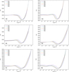 |
Fig. 1 Temperature structure for models O6 (upper left panel), O8 (upper right panel), B0 (middle left panel), B2 (middle right panel), B4 (lower left panel), and B6 (lower right panel) for all values of the clumping factor (D = 1, …, 8). |
4.3 Non-equilibrium atomic level populations
The NLTE effects in our model atmospheres cause departures from equilibrium values of atomic level number densities ni and also strong ionisation shifts towards lower ionisation states for optically thin parts of the atmospheres. To eliminate the effect of the ionisation shift from departure coefficients, we used the common definition of LTE populations in NLTE models, that is with respect to the ground level of the next highest ion (see Hubeny & Mihalas 2015, Eq. (14.228)). This means that we divided the b-factors obtained from our models by the b-factor of the ground level of the next highest ion (current version of our code uses b-factors after the original definition of Menzel 1937). To give a more specific example, we divided the b-factor of the He I 1s 1S level by the b-factor of the He II n = 1 level. We plotted these b-factors for the lowest levels of each ion included in the model calculation (Figs. 7, 8 and A.1 to A.5).
There is a trend of an increase of b-factors with lower effective temperatures; this is valid for both clumped and unclumped model atmospheres. There is a remarkable similarity between b-factors and their changes with clumping between the hottest models of our sample (models 55-4, O6, and O8), although they are calculated for significantly different stellar masses and radii. The upper boundary of the line formation region can be roughly determined by the optical depth in the line centre as the place where this optical depth is between 2/3 and 1. This is indicated for the H I and He II L α lines by arrows in the upper and bottom panels of Figs. 7, A.1 and A.2, respectively. Interestingly, the ‘bump’ in the depth dependence of the b-factor of the n = 2 level (which is usually connected with the corresponding line formation region) moves outwards, while the region of L α formation (measured by the optical depth in the line centre) does not. This is most probably caused by the effect of collisions, which are enhanced for a clumped atmosphere. Farther in the atmosphere at low optical depths, collisions are less frequent and radiative rates dominate. Enhanced b-factors for the ground levels for clumped atmospheres there are caused by an increased recombination rate due to clumping. The effect of collisions can be observed also at the continuum formation region (τR ≈ 1), for clumped atmospheres b-factors start to deviate from the equilibrium value at higher r (lower m).
For cooler models from our sample, only the H I Lα line formation region is indicated in Figs. 8 and A.3–A.5. For the case of the B0 model, the He II Lα line is optically thick throughout the model atmosphere, while for the B2 model this optical thickness was assumed (the line was put to the detailed radiative balance). For models B4 and B6, the He II ion was not considered at all due to its low abundance, which caused numerical problems.
For practically all stars where the ionised helium was considered, very large values of b-factors of the ground level of He II are noticeable. This is a typical NLTE effect for strong resonance lines combined with a strong NLTE effect of an active continuum (which behaves like a resonance line; see Hubeny & Mihalas 2015, Chapter 14.6). This leads to a massive overpopulation of the ground level and to an ionisation shift towards He II (depopulation of He III) for m ≳ 10−2.
Effects for He I levels are more complex due to a different atomic structure. For all models, there is a rise of the b-factor for the ground level of He I for low m. For the hottest models this rise follows a significant decrease just above τR ≈ 1. Somewhat similar behaviour is seen for the metastable 2s 1S level; described effects are weaker, however. In addition, this level is closely coupled with the 2p 1P level below the formation region of the corresponding line between these levels (20 587 Å). Above this region, standard behaviour (rise of the b-factor of the lower level and decrease of the b-factor of the upper level) is observed. The behaviour of the corresponding triplet levels (2s 3S and 2p 3P) is qualitativelysimilar; collisional coupling between singlet and triplet levels plays a role in a rise of departure coefficients of the displayed triplet levels. Above the formation region of the 10 830 Å line, a similar behaviour to that of singlet levels is seen. The behaviour of displayed He I b-factors is also influenced by interactions with other levels taken into account (up to n = 4 all fine structure levels in detail; from n = 5 up to n = 9 two mean levels for each quantum number n, one for singlets and one for triplets).
5 Discussion
Using our model atmosphere calculations, we studied the effect of clumping on the atmospheric structure of 1D static NLTE model atmospheres of hot dwarf stars. Standard studies of clumping take the atmospheric structure (density and temperature) as given and study the effects of clumping on radiative transfer and line formation.
Our calculations clearly show the effect of clumping on the vertical structure of 1D NLTE model atmospheres. However, due to the 3D nature of clumping, inclusion of clumping in 1D models must suffer from approximations. Here, we used the common and simplest approximate 1D description of clumping, which assumes that clumps are smaller than the photon mean-free path (Hamann & Koesterke 1998) and means that the clumps are optically thin. This description is also referred to as the filling factor approach (Hillier 1996; Hillier & Miller 1999) or microclumping (see Oskinova et al. 2007) and uses the clumping factor D (see Eq. (3)) and the volume filling factor fvol (see Eq. (2)) for a quantitative description of clumping. The advantage is that its solution lies in the radiative transfer equation with the same effort as that of a horizontally homogeneous (smooth) atmosphere without clumps (Hillier 2000).
All resulting models are hotter in the region of continuum formation for larger clumping factors D. This backwarming effect is predominantly caused by increasing the local Rosseland mean opacity.
In our calculations, we assumed no clumping at significant depths. Evidently, the single assumption of optically thin clumps is also acceptable at great optical depths in the diffusion approximation region, and it causes a corresponding enhancement of the opacity. However, the complete model of dense clumps (which must be very dense there) and a void interclump medium is far from a realistic one at great optical depths, unless the matter is in a solid state there. To avoid this unrealistic situation, we used a simplifying assumption of no clumping (D = 1) at great depths (τR ≳ 2∕3). To check the effect of clumping at the dense part of the atmospheres, we also calculated corresponding models with clumping at great depths. Results of these calculations without the latter assumption, for a clumping factor that is constant throughout the atmosphere, are shown in Fig. A.6 for the case of the model 55-4. This clumping model causes heating of the inner layers of the atmosphere, larger clumping factor D causes higher temperatures, while the layers above τR ≳ 2∕3 are almost the same as in the case of no clumping in dense atmospheric parts (cf. Fig. 2). Enhanced heating in the inner parts of the atmospheres causes larger emergent flux in the Lyman series wavelength region (see Fig. A.7). We may conclude that clumping in the inner atmospheric parts enhances the effects of the emergent flux described in Sect. 4.2; however, due to approximated 1D treatment of clumping, this conclusion has to be taken with care. In any case, these effects underline the sensitivity of stellar atmospheres to different ways of clumping treatment.
The really problematic region is the radiation formation region, around τ(ν) ≈ 1, where clumps may easily become larger than the photon mean-free path at a frequency ν. The only opacity influenced by the clumping factor in the optically thin approximation is the free-free opacity, which is D times larger. The bound-free and bound-bound opacities are the same as for the horizontally homogeneous (smooth) atmosphere. However, in reality the bound-bound and bound-free opacities in clumps may also become large, causing the increase of the clump optical thickness τcl (ν) above 1 even for the case when τ(ν) ≲ 1 (τ(ν) is evaluated using the mean opacity χmean, see Eq. (9a)). There, a 3D description should be preferred to include different properties of radiation transfer through clumps (which may be optically thick) and the interclump medium (which is optically thin, or in our case even void) in comparison to the smooth atmosphere, which may be optically thin. Consequently, the optically thin clumping assumption underestimates the effect of clumping.
Another effect of clumping is more indirect and follows from the kinetic equilibrium equations and changes in the emission coefficient. This also includes the enhancement of collisional processes in clumps due to higher density there and their dependence on the product ne ni, and, in the case of collisional recombination, even on  (ni is the corresponding atomic level number density).
As the clumping causes changes to the stellar emergent flux, it may affect basic stellar parameter determination using model atmospheres. Our NLTE models of clumped atmospheres of dwarf stars show higher flux in parts of the UV region and lower flux in the visual and infrared regions. This may cause the opposite effect to that of line blanketing. Atmospheres may appear cooler in the visual region. However, our set of parametersshowed only small changes in the flux, at maximum several percent, which lessens the significance of this effect. Our data indicate that the effect of clumping is smaller for lower stellar effective temperatures; to definitively confirm this statement, a more extended set of models would be necessary. Furthermore, the effect on the emergent flux (which is opposite to the effect of line blanketing) has to be verified using line-blanketed NLTE model atmospheres.
Besides continuum flux, some spectral lines are also affected. However, we cannot make a simple conclusion as to whether clumping causes the strengthening or weakening of spectral lines, as we found both effects for the same models. However, the changes are quite significant and likely affect the analysis; for example, with regard to the abundance determination. Unfortunately, the chemical composition of our models (only H+He) is too simple for real stars and prevents us from making a direct comparison with observed stellar spectra and testing the expected effects on abundance determination.
We also assumed microclumping (all clumps are optically thin). This assumption, often used in the analysis of stellar winds, limits the clump properties and only allows us to study basic effects of clumping. As in the case of stellar winds, it is used mainly to simplify the problem. On the other hand, in reality some clumps may easily become optically thick, either due to the enhancement of density or through a more subtle effect of relaxing the assumption of LTE. A generalised description of clumping (which allows macroclumping: i.e. optically thick clumping) developed by Sundqvist et al. (2014) and used in stellar wind calculations by Sundqvist & Puls (2018) uses an additional free parameter h (the porosity length). We decided to avoid introducing an additional free parameter, the depth dependence of which is still a matter of discussion, and study the basic clumping effects in 1D static NLTE model atmospheres.
There is, of course, an uncertainty which values of the clumping factor D are the proper ones for the case of static atmospheres. The clumping factor D describes the density contrast of the clumped medium, so the high D also means significant enhancement of density inside clumps, and there should be a physical reason for this. If the clumping originates due to the sub-photospheric convection (Cantiello et al. 2009), we can expect density contrasts related to the contrasts within sub-photospheric convective cells. Consequently, we do not expect this contrast to be too high, so our decision to limit our calculations to clumping factors D ≤ 8 is reasonable. In any case, to account for clumping properly, 3D models are to be preferred.
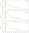 |
Fig. 3 UV and visual flux for main-sequence models O6 (upper panel), O8 (middle panel), and B0 (lower panel). For global model parameters, see Table 1. |
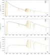 |
Fig. 4 Same as Fig. 3, but for main-sequence models B2 (upper panel), B4 (middle panel), and B6 (lower panel). |
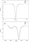 |
Fig. 6 Selected normalised line profiles for the O6 model for clumping factors D = 1, 2, 4, 8. Upper panel:He II Hα line profile. Lower panel: He II Piα (4–6, 10 123 Å) and H I Pδ line with an emission peak of the He II 6–14 line (10 048 Å) line profiles. |
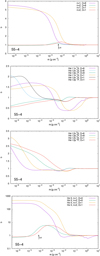 |
Fig. 7 Departure coefficients (b-factors) for clumpingfactors D = 1 and D = 8 and for selected atomic levels for a set of model atmospheres 55-4 (for basic global model parameters, see Table 1). From the top panel: H I n = 1 and n = 2 levels; He I 1s 1S, 2s 1S, and 2p 1P levels; He I 2s 3S and 2p 3P levels; He II n = 1 and n = 2 levels. |
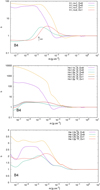 |
Fig. 8 Departure coefficients (b-factors) for selected atomic levels for clumping factors D = 1 and D = 8 and for a set of model atmospheres B4 (for basic global model parameters, see Table 1). From the top panel: H I n = 1 and n = 2; He I 1s 1S, 2s 1S, and 2p 1P; He I 2s 3S and 2p 3P. |
6 Conclusions
We present the first 1D static NLTE model atmospheres of dwarf stars that consistently include the effect of optically thin clumping on the vertical structure of the stellar atmosphere, in addition to its influence on the emerging radiation. Our models show differences between clumped and unclumped model atmospheres, even for the case of a simplifying assumption of clumps smaller than the photon mean-free path (optically thin clumping). For the more general case of optically thick clumps, greater effects can be expected. However, this case has to be solved using 3D modelling.
Acknowledgements
The authors thank to the anonymous referee for his/her valuable comments to the manuscript. This research has made use of the NASA’s Astrophysics Data System Abstract Service. This research was supported by a grant 18-05665S (GAČR). The Astronomical Institute Ondřejov is supported by the project RVO:67985815.
Appendix A Additional figures
References
- Asplund, M., & Lind, K. 2010, in IAU Symposium, 268, Light Elements in the Universe, eds. C. Charbonnel, M. Tosi, F. Primas, & C. Chiappini, 191 [Google Scholar]
- Auer, L. H. 1971, J. Quant. Spec. Radiat. Transf., 11, 573 [NASA ADS] [CrossRef] [Google Scholar]
- Bergemann, M., Gallagher, A. J., Eitner, P., et al. 2019, A&A, 631, A80 [NASA ADS] [CrossRef] [EDP Sciences] [Google Scholar]
- Bjørgen, J. P., & Leenaarts, J. 2017, A&A, 599, A118 [NASA ADS] [CrossRef] [EDP Sciences] [Google Scholar]
- Cantiello, M., Langer, N., Brott, I., et al. 2009, A&A, 499, 279 [NASA ADS] [CrossRef] [EDP Sciences] [Google Scholar]
- Chandrasekhar, S., & Münch, G. 1952, ApJ, 115, 103 [NASA ADS] [CrossRef] [Google Scholar]
- Feldmeier, A., Oskinova, L., & Hamann, W.-R. 2003, A&A, 403, 217 [NASA ADS] [CrossRef] [EDP Sciences] [Google Scholar]
- Fišák, J., Kubát, J., Kubátová, B., Kromer, M., & Krtička, J. 2019, in ASP Conference Series, 519, Radiative Signatures from the Cosmos, eds. K. Werner, C. Stehlé, T. Rauch, & T. M. Lanz (Astronomical Society of the Pacific), 15 [Google Scholar]
- Freytag, B., Steffen, M., Ludwig, H. G., et al. 2012, J. Comput. Phys., 231, 919 [Google Scholar]
- Freytag, B., Höfner, S., & Liljegren, S. 2019, IAU Symp., 343, 9 [NASA ADS] [Google Scholar]
- Grassitelli, L., Chené, A. N., Sanyal, D., et al. 2016, A&A, 590, A12 [NASA ADS] [CrossRef] [EDP Sciences] [Google Scholar]
- Gruschinske, J., & Kudritzki, R. P. 1979, A&A, 77, 341 [Google Scholar]
- Gu, Y., Lindsey, C., & Jefferies, J. T. 1995, ApJ, 450, 318 [NASA ADS] [CrossRef] [Google Scholar]
- Hamann, W.-R., & Koesterke, L. 1998, A&A, 335, 1003 [NASA ADS] [Google Scholar]
- Hamann, W.-R., & Gräfener, G. 2004, A&A, 427, 697 [NASA ADS] [CrossRef] [EDP Sciences] [Google Scholar]
- Harmanec, P. 1988, Bull. Astron. Inst. Czechosl., 39, 329 [Google Scholar]
- Hennicker, L., Puls, J., Kee, N. D., & Sundqvist, J. O. 2018, A&A, 616, A140 [NASA ADS] [CrossRef] [EDP Sciences] [Google Scholar]
- Hennicker, L., Puls, J., Kee, N. D., & Sundqvist, J. O. 2020, A&A, 633, A16 [NASA ADS] [CrossRef] [EDP Sciences] [Google Scholar]
- Hillier, D. J. 1996, in Liège International Astrophysical Colloquia, 33, WR stars in the Framework of Stellar Evolution, eds. J. M. Vreux, A. Detal, D. Fraipont-Caro, E. Gosset, & G. Rauw, 509 [Google Scholar]
- Hillier, D. J. 2000, in ASP Conference Series, 204, Thermal and Ionization Aspects of Flows from Hot Stars, eds. H. Lamers, & A. Sapar (Astronomical Society of the Pacific), 161 [Google Scholar]
- Hillier, D. J., & Miller, D. L. 1998, ApJ, 496, 407 [NASA ADS] [CrossRef] [Google Scholar]
- Hillier, D. J., & Miller, D. L. 1999, ApJ, 519, 354 [Google Scholar]
- Hubeny, I. 2019, in ASP Conference Series, 519, Radiative Signatures from the Cosmos, eds. K. Werner, C. Stehlé, T. Rauch, & T. M. Lanz (Astronomical Society of the Pacific), 75 [Google Scholar]
- Hubeny, I., & Mihalas, D. 2015, Theory of Stellar Atmospheres (Princeton: Princeton University Press) [Google Scholar]
- Jiang, Y.-F., Cantiello, M., Bildsten, L., Quataert, E., & Blaes, O. 2015, ApJ, 813, 74 [Google Scholar]
- Jiang, Y.-F., Cantiello, M., Bildsten, L., et al. 2018, Nature, 561, 498 [NASA ADS] [CrossRef] [Google Scholar]
- Krtička, J., Kubát, J., & Krtičková, I. 2016, A&A, 593, A101 [NASA ADS] [CrossRef] [EDP Sciences] [Google Scholar]
- Krtička, J., Kubát, J., & Krtičková, I. 2018, A&A, 620, A150 [NASA ADS] [CrossRef] [EDP Sciences] [Google Scholar]
- Kubát, J. 1994, A&A, 287, 179 [Google Scholar]
- Kubát, J. 1996, A&A, 305, 255 [NASA ADS] [Google Scholar]
- Kubát, J. 1997a, A&A, 323, 524 [NASA ADS] [Google Scholar]
- Kubát, J. 1997b, A&A, 326, 277 [NASA ADS] [Google Scholar]
- Kubát, J. 2001, A&A, 366, 210 [NASA ADS] [CrossRef] [EDP Sciences] [Google Scholar]
- Kubát, J. 2003, in IAU Symposium, 210, Modelling of Stellar Atmospheres, eds. N. Piskunov, W. W. Weiss, & D. F. Gray, A8 [Google Scholar]
- Kubát, J. 2012, ApJS, 203, 20 [CrossRef] [Google Scholar]
- Kubát, J., & Kubátová, B. 2019, in ASP Conference Series, 519, Radiative Signatures from the Cosmos, eds. K. Werner, C. Stehlé, T. Rauch, & T. M. Lanz (Astronomical Society of the Pacific), 45 [Google Scholar]
- Kubát, J., Puls, J., & Pauldrach, A. W. A. 1999, A&A, 341, 587 [NASA ADS] [Google Scholar]
- Kubátová, B., Hamann, W. R., Todt, H., et al. 2015, in Wolf-Rayet Stars, eds. W.-R. Hamann, A. Sander, & H. Todt (Potsdam Univ.-Verl.), 125 [Google Scholar]
- Kunasz, P. B., Hummer, D. G., & Mihalas, D. 1975, ApJ, 202, 92 [NASA ADS] [CrossRef] [Google Scholar]
- Leenaarts, J.,& Carlsson, M. 2009, in ASP Conference Series, 415, The Second Hinode Science Meeting: Beyond Discovery-Toward Understanding, eds. B. Lites, M. Cheung, T. Magara, J. Mariska, & K. Reeves (Astronomical Society of the Pacific), 87 [Google Scholar]
- Lucy, L. B., & Solomon, P. M. 1970, ApJ, 159, 879 [Google Scholar]
- Ludwig, H. G., & Steffen, M. 2016, Astron. Nachr., 337, 844 [NASA ADS] [CrossRef] [Google Scholar]
- Menzel, D. H. 1937, ApJ, 85, 330 [CrossRef] [Google Scholar]
- Mihalas, D., & Auer, L. H. 1970, ApJ, 160, 1161 [NASA ADS] [CrossRef] [Google Scholar]
- Mihalas, D., & Hummer, D. G. 1974, ApJS, 28, 343 [NASA ADS] [CrossRef] [Google Scholar]
- Muijres, L. E., de Koter, A., Vink, J. S., et al. 2011, A&A, 526, A32 [NASA ADS] [CrossRef] [EDP Sciences] [Google Scholar]
- Nordlander, T., Amarsi, A. M., Lind, K., et al. 2017, A&A, 597, A6 [NASA ADS] [CrossRef] [EDP Sciences] [Google Scholar]
- Nordlund, Å., & Stein, R. F. 2009, in AIP Conf. Ser., 1171, Recent Directions in Astrophysical Quantitative Spectroscopy and Radiation Hydrodynamics, eds. I. Hubeny, J. M. Stone, K. MacGregor, & K. Werner, 242 [Google Scholar]
- Oskinova, L. M., Hamann, W.-R., & Feldmeier, A. 2007, A&A, 476, 1331 [NASA ADS] [CrossRef] [EDP Sciences] [Google Scholar]
- Owocki, S. P., & Sundqvist, J. O. 2018, MNRAS, 475, 814 [NASA ADS] [CrossRef] [Google Scholar]
- Owocki, S. P., Castor, J. I., & Rybicki, G. B. 1988, ApJ, 335, 914 [NASA ADS] [CrossRef] [Google Scholar]
- Owocki, S. P., Gayley, K. G., & Shaviv, N. J. 2004, ApJ, 616, 525 [NASA ADS] [CrossRef] [Google Scholar]
- Pomraning, G. C. 1991, Linear Kinetic Theory and Particle Transport in Stochastic Mixtures, Series on Advances in Mathematics for Applied Sciences, v. 7 (Singapore: World Scientific) [CrossRef] [Google Scholar]
- Puls, J., Urbaneja, M. A., Venero, R., et al. 2005, A&A, 435, 669 [NASA ADS] [CrossRef] [EDP Sciences] [Google Scholar]
- Sander, A. A. C., & Vink, J. S. 2020, MNRAS, 499, 873 [Google Scholar]
- Santolaya-Rey, A. E., Puls, J., & Herrero, A. 1997, A&A, 323, 488 [NASA ADS] [Google Scholar]
- Schuster, A. 1905, ApJ, 21, 1 [NASA ADS] [CrossRef] [Google Scholar]
- Stein, R. F., & Nordlund, Å. 1998, ApJ, 499, 914 [NASA ADS] [CrossRef] [Google Scholar]
- Steffen, M., Prakapavičius, D., Caffau, E., et al. 2015, A&A, 583, A57 [NASA ADS] [CrossRef] [EDP Sciences] [Google Scholar]
- Sundqvist, J. O., & Puls, J. 2018, A&A, 619, A59 [NASA ADS] [CrossRef] [EDP Sciences] [Google Scholar]
- Sundqvist, J. O., Puls, J., & Feldmeier, A. 2010, A&A, 510, A11 [NASA ADS] [CrossRef] [EDP Sciences] [Google Scholar]
- Sundqvist, J. O., Puls, J., Feldmeier, A., & Owocki, S. P. 2011, A&A, 528, A64 [NASA ADS] [CrossRef] [EDP Sciences] [Google Scholar]
- Sundqvist, J. O., Puls, J., & Owocki, S. P. 2014, A&A, 568, A59 [NASA ADS] [CrossRef] [EDP Sciences] [Google Scholar]
- Sundqvist, J. O., Owocki, S. P., & Puls, J. 2018, A&A, 611, A17 [NASA ADS] [CrossRef] [EDP Sciences] [Google Scholar]
- Šurlan, B., Hamann, W.-R., Kubát, J., Oskinova, L. M., & Feldmeier, A. 2012, A&A, 541, A37 [NASA ADS] [CrossRef] [EDP Sciences] [Google Scholar]
- Šurlan, B., Hamann, W.-R., Aret, A., et al. 2013, A&A, 559, A130 [NASA ADS] [CrossRef] [EDP Sciences] [Google Scholar]
- Trampedach, R., Asplund, M., Collet, R., Nordlund, Å., & Stein, R. F. 2013, ApJ, 769, 18 [NASA ADS] [CrossRef] [Google Scholar]
- Werner, K., Stehlé, C., Rauch, T., & Lanz, T. M. 2019, ASP Conference Series, 519, Radiative Signatures from the Cosmos (Astronomical Society of the Pacific) [Google Scholar]
- Wilson, P. R. 1968, ApJ, 151, 1029 [NASA ADS] [CrossRef] [Google Scholar]
- Wilson, P. R. 1969, ApJ, 155, 715 [CrossRef] [Google Scholar]
We note that in Kubát & Kubátová (2019) the mean number density values were incorrectly used in thermal balance equations.
All Tables
All Figures
|
Fig. 1 Temperature structure for models O6 (upper left panel), O8 (upper right panel), B0 (middle left panel), B2 (middle right panel), B4 (lower left panel), and B6 (lower right panel) for all values of the clumping factor (D = 1, …, 8). |
| In the text | |
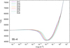 |
Fig. 2 Same as Fig. 1, but for models 55-4. |
| In the text | |
|
Fig. 3 UV and visual flux for main-sequence models O6 (upper panel), O8 (middle panel), and B0 (lower panel). For global model parameters, see Table 1. |
| In the text | |
|
Fig. 4 Same as Fig. 3, but for main-sequence models B2 (upper panel), B4 (middle panel), and B6 (lower panel). |
| In the text | |
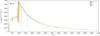 |
Fig. 5 Same as Fig. 3, but for subdwarf models 55-4. |
| In the text | |
|
Fig. 6 Selected normalised line profiles for the O6 model for clumping factors D = 1, 2, 4, 8. Upper panel:He II Hα line profile. Lower panel: He II Piα (4–6, 10 123 Å) and H I Pδ line with an emission peak of the He II 6–14 line (10 048 Å) line profiles. |
| In the text | |
|
Fig. 7 Departure coefficients (b-factors) for clumpingfactors D = 1 and D = 8 and for selected atomic levels for a set of model atmospheres 55-4 (for basic global model parameters, see Table 1). From the top panel: H I n = 1 and n = 2 levels; He I 1s 1S, 2s 1S, and 2p 1P levels; He I 2s 3S and 2p 3P levels; He II n = 1 and n = 2 levels. |
| In the text | |
|
Fig. 8 Departure coefficients (b-factors) for selected atomic levels for clumping factors D = 1 and D = 8 and for a set of model atmospheres B4 (for basic global model parameters, see Table 1). From the top panel: H I n = 1 and n = 2; He I 1s 1S, 2s 1S, and 2p 1P; He I 2s 3S and 2p 3P. |
| In the text | |
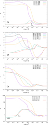 |
Fig. A.1 Same as Fig. 7, but for the model set O6. |
| In the text | |
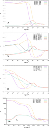 |
Fig. A.2 Same as Fig. 7, but for the model set O8. |
| In the text | |
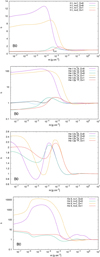 |
Fig. A.3 Same as Fig. 7, but for the model set B0. |
| In the text | |
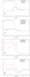 |
Fig. A.4 Same as Fig. 7, but for the model set B2. |
| In the text | |
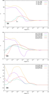 |
Fig. A.5 Same as Fig. 8, but for the model set B6. |
| In the text | |
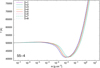 |
Fig. A.6 Same as Fig. 2, but with a depth-independent clumping factor. |
| In the text | |
 |
Fig. A.7 Same as Fig. 5, but with a depth-independent clumping factor. |
| In the text | |
Current usage metrics show cumulative count of Article Views (full-text article views including HTML views, PDF and ePub downloads, according to the available data) and Abstracts Views on Vision4Press platform.
Data correspond to usage on the plateform after 2015. The current usage metrics is available 48-96 hours after online publication and is updated daily on week days.
Initial download of the metrics may take a while.