Fig. 4.
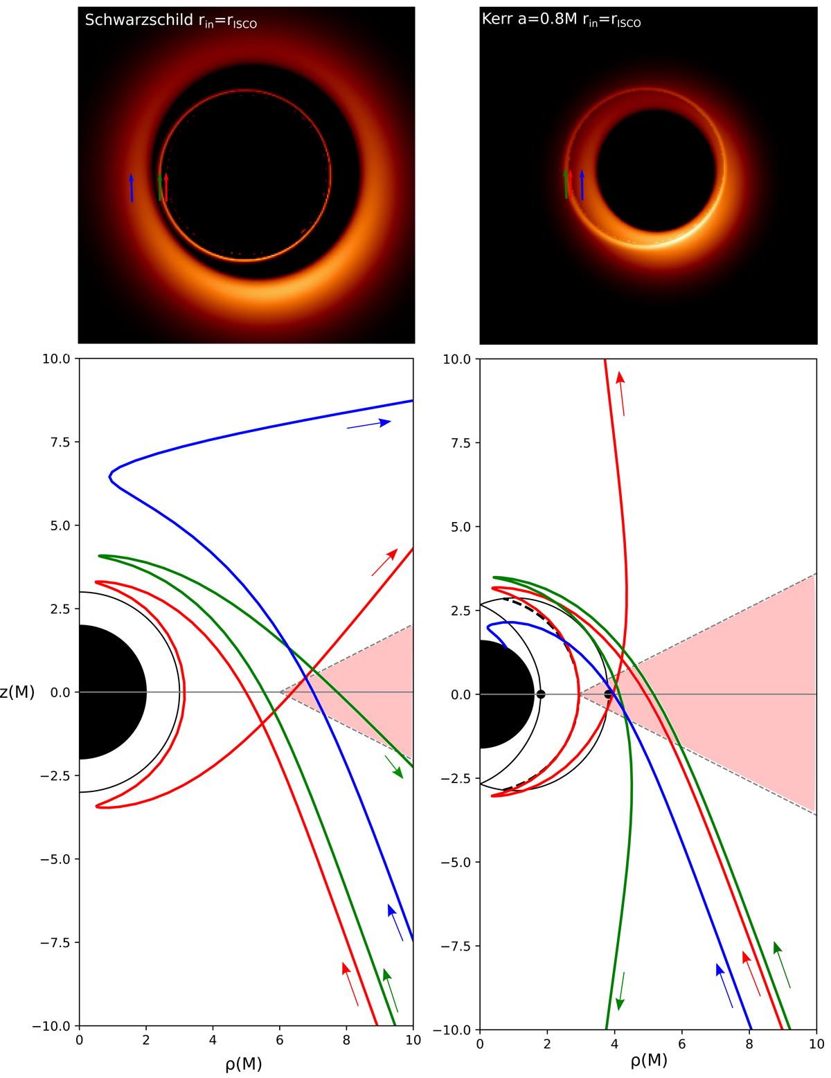
Top panels: zoom on the central 80 μas field of the image of a thick disk surrounding a Schwarzschild black hole (left) or a Kerr black hole with spin parameter a = 0.8M (right). Bottom panels: three geodesics are plotted on the (ρ, z) plane of height vs. cylindrical radius (in units of M). The arrows show the direction of backward-ray-tracing integration in GYOTO. The observer is located at 16.9 Mpc toward the bottom right of the panels. These geodesics correspond to the pixels labeled by the red, green, and blue arrows of the top panels, which are, respectively, part of the photon ring (3 crossings of the equatorial plane), lensing ring (2 crossings), and primary image (1 crossing) in the terminology of Gralla et al. (2019). The half disk filled in black corresponds to the event horizon. The black solid half circle of the left panel corresponds to the Schwarzschild photon sphere at r = 3M. The black-line delineated white crescent of the right panel corresponds to the locus of spherical Kerr orbits for a = 0.8M, with the locations of the prograde and retrograde equatorial photon orbits denoted by black dots. The dashed thick black line within the crescent corresponds to the spherical orbit at the inner Boyer-Lindquist radius of the red geodesic. The thick disk corresponds to the pale red region. In the Schwarzschild case (left panel), the red geodesic approaches the photon sphere. In the Kerr case (right panel), the red geodesic approaches a spherical orbit at its minimum Boyer-Lindquist radius. Both the red and green geodesics belong to the secondary ring.
Current usage metrics show cumulative count of Article Views (full-text article views including HTML views, PDF and ePub downloads, according to the available data) and Abstracts Views on Vision4Press platform.
Data correspond to usage on the plateform after 2015. The current usage metrics is available 48-96 hours after online publication and is updated daily on week days.
Initial download of the metrics may take a while.