Fig. A.2.
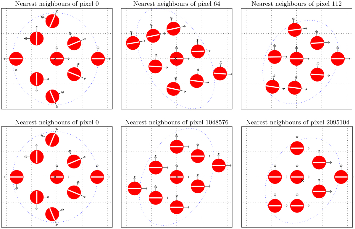
Examples of the finite-difference stencils for HEALPix pixels with eight (left and centre) and seven (right) neighbours for Nside = 8 (top) and Nside = 1024 (bottom) in ring ordering (see also Bowyer et al. 2011). Red circles represent positions of HEALPix pixel centres in a gnomonic projection onto a plane tangent to the central pixel (i.e., looking straight down at the tangent plane), with the dotted grid aligned with local ![]() and
and ![]() directions, illustrating the average pixel pitch h = (π/3)1/2/Nside. The white bars represent the directions of polarization, specifically the direction of the polarization ellipse for the +Q polarization mode. Single- and double-arrow vectors show projections of
directions, illustrating the average pixel pitch h = (π/3)1/2/Nside. The white bars represent the directions of polarization, specifically the direction of the polarization ellipse for the +Q polarization mode. Single- and double-arrow vectors show projections of ![]() and
and ![]() directions, respectively, for neighbouring pixels onto the tangent plane. The black cross corresponds to the average pixel position, while the blue dotted ellipse represents the pixel position covariance. Although for some positions on the sky, the polarization directions are aligned, this is not at all true near the poles (pixel 0); hence just adding Q and U does not make sense. Additionally we can see that because the grid is distorted, second-order finite-difference schemes need more than just nearest neighbours to work.
directions, respectively, for neighbouring pixels onto the tangent plane. The black cross corresponds to the average pixel position, while the blue dotted ellipse represents the pixel position covariance. Although for some positions on the sky, the polarization directions are aligned, this is not at all true near the poles (pixel 0); hence just adding Q and U does not make sense. Additionally we can see that because the grid is distorted, second-order finite-difference schemes need more than just nearest neighbours to work.
Current usage metrics show cumulative count of Article Views (full-text article views including HTML views, PDF and ePub downloads, according to the available data) and Abstracts Views on Vision4Press platform.
Data correspond to usage on the plateform after 2015. The current usage metrics is available 48-96 hours after online publication and is updated daily on week days.
Initial download of the metrics may take a while.