| Issue |
A&A
Volume 634, February 2020
|
|
|---|---|---|
| Article Number | A101 | |
| Number of page(s) | 16 | |
| Section | Extragalactic astronomy | |
| DOI | https://doi.org/10.1051/0004-6361/201834740 | |
| Published online | 17 February 2020 | |
Multiple black hole system in 4C31.61 (2201+315)
1
Institut d’Astrophysique, UPMC Univ. Paris 06, CNRS, UMR 7095, 98 bis Bd Arago, 75014 Paris, France
e-mail: This email address is being protected from spambots. You need JavaScript enabled to view it.
2
Laboratoire d’Astrophysique de Bordeaux, Univ. Bordeaux, CNRS, B18N, Allée Geoffroy Saint-Hilaire, 33615 Pessac, France
3
SYRTE, Observatoire de Paris, Université PSL, CNRS, Sorbonne Université, LNE, France
Received:
29
November
2018
Accepted:
11
December
2019
Abstract
Modeling trajectories of radio components ejected by the nucleus of 4C31.61 (2201+315) and observed by very long baseline interferometry (VLBI) in the frame of the MOJAVE survey suggests that they are ejected from three different origins that possibly host three different supermassive black holes. These origins correspond to three stationary components, one of which one is the VLBI core. Most of the mass of the nucleus is associated with a supermassive binary black hole system whose separation is ≈0.3 milliarc second, that is, a distance of ≈1.3 parsec and the mass ratio is ≈2. In contrast, the mass ratio with respect to the third black hole is ≈1/100. The three origins lie within 0.6 milliarc second, or a distance of ≈2.6 parsec. Based in this structure of the nucleus, we explain the variations observed in the astrometric coordinate time series obtained from VLBI geodetic surveys. This study shows that it is possible to exploit large MOJAVE-like VLBI databases to propose more insights into the structure of the extragalactic radio sources that are targeted by VLBI in geodetic and astrometry programs.
Key words: astrometry / galaxies: jets / galaxies: individual: 2201+315
© J. Roland et al. 2020
 Open Access article, published by EDP Sciences, under the terms of the Creative Commons Attribution License (https://creativecommons.org/licenses/by/4.0), which permits unrestricted use, distribution, and reproduction in any medium, provided the original work is properly cited.
1. Introduction
Very long baseline interferometry (VLBI) observations of nuclei of extra galactic radio sources show that the ejection of VLBI components does not follow a straight line, but wiggles. These observations suggest a precession of the accretion disk that can be explained if the nuclei contain either a spinning single black hole (BH) or a binary black hole (BBH) system. We developed a minimization method by first modeling the ejection of a VLBI component by a spinning single BH, which produces the precession of the accretion disk. Then we modeled the ejection of a VLBI component by a BBH system, taking the precession of the accretion disk and the motion of the BHs into account.
The method has been applied to 0420-014 (Britzen et al. 2001), 3C 345 (Lobanov & Roland 2005), 1803+784 (Roland et al. 2008), 1823+568 and 3C 279 (Roland et al. 2013), and 1928+738 (Roland et al. 2015). Modeling VLBI ejections produces evidence that nuclei of extragalactic radio sources contain BBH systems. These systems can form when galaxies merge (Begelman et al. 1980), and Britzen et al. (2001) suggested that if nuclei of extragalactic radio sources contain BBH systems, the association of extragalactic radio sources with elliptical galaxies can be explained. It also explains why quasars (quasi-stellar radio sources) represent about 5% of the quasi-stellar objects (QSO). For reviews for the formation of BBH systems in galaxy mergers, see Colpi & Dotti (2011), Colpi (2014), and Volonteri et al. (2016).
When a nucleus contains a BBH system, the two BHs can eject VLBI components, and both can be detected using VLBI observations. In this case, we observe the core and one stationary component, and we observe two families of trajectories. This is, for instance, the case for 3C 279 (Roland et al. 2013) and 1928+738 (Roland et al. 2015). However, it is not always the case, and in some cases, only one BH can be detected using VLBI observations, the other being “inactive”.
In this article, we use for the Hubble constant Ho ≈ 73 km s−1 Mpc−1 and DL ≈ 1460 Mpc for the luminosity distance of 2201+315 and model the ejection of the VLBI components of 4C31.61 ≡ 2201+315 using data from the Monitoring Of Jets in Active galactic nuclei with VLBA Experiments (MOJAVE), that is, the 15 GHz observations and the definitions of the different components of Table 3 of Lister et al. (2019). The analysis of MOJAVE data with our minimization method suggests that the nucleus of 2201+315 contains three BHs associated with the stationary components C0 (the core), C3, and C9 (see Fig. 1). Most of the mass of the nucleus is associated with the BBH system C0–C9, whose separation is  mas, corresponding to a projected linear distance
  pc, and the mass ratio is MC9/MCO = 2 ± 0.5. The mass of the third BH is MC3/(MC0 + MC9) ≈ 1/100. The distance between C0 and C3 is
  mas, which translates into ≈2.4 pc. Calling G, the center of gravity of the system C0–C9, the distance between component C3 and the center of gravity G is
  mas, that is, ≈1.6 pc (see Table 1).
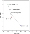 |
Fig. 1. Structure of the nucleus of 2201+315. The analysis of MOJAVE data with our minimization method suggests that the nucleus of 2201+315 contains three BHs. G is the center of gravity of the BBH system C0–C9 and L1 is the first Lagrange point of the BBH system C0–C9; this is the point where the gravitational forces of the BHs C0 and C9 are equal. In order to obtain a stable solution, the radii of the accretion disks around C0 and C9 have to be smaller than the distances L1–C0 and L1–C9, respectively. |
Distances between the different BH.
We show that component C6 is ejected from the core C0, component C7 is ejected from the stationary component C3, and component C13 is ejected from the stationary component C9. We deduce the characteristics of the BBH system constituted by the core C0 and the stationary component C9. We also deduce the characteristics of the third BH that is associated with the stationary component C3. Finally, knowing the structure of the nucleus of 2201+315, we discuss the influence of the variations in the ratio of the flux densities of the three BHs and of the ejection of a new VLBI component on the coordinate time series obtained by the analysis of geodetic VLBI observations (Gattano et al. 2018).
2. Methods and data
2.1. Properties of the BBH system solution
To model the ejection of a VLBI component, we assumed that the VLBI component corresponds to the relativistic ejection of an electron–positron (e−e+) plasma referred to as the beam. It is surrounded by a subrelativistic electron–proton (e−p) plasma called the jet. The relativistic beam is responsible for the formation of VLBI components, their synchrotron radio emission, and inverse Compton emission in the UV, X-rays, and γ-rays. The subrelativistic electron–proton jet that carries most of the mass and kinetic energy ejected by the BH is responsible for the formation of kiloparsec jets, hot spots, and extended lobes. The magnetic field in the beam and the mixing layer between the beam and the jet is parallel to the flow, and the magnetic field in the jet rapidly becomes toroidal. This model is called the two-fluid model (Fig. 2; see also Roland et al. 2013, and references therein). The beam can propagate along the magnetic lines and is stable if the bulk Lorentz factor, γc of the ejected VLBI component is γc < 30 and if the magnetic field in the beam and in the mixing layer is grater than a critical value Bc. The beam and the jet are perturbed by the precession of the accretion disk and the motion of the BHs.
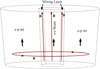 |
Fig. 2. Two-fluid model. The outflow consists of an e− − e+ plasma, the beam, which moves at a highly relativistic speed and is surrounded by an e− − p plasma, and of the jet, which moves at a mildly relativistic speed. |
When in addition to the radio, optical observations are available that peak in the light curve, this optical emission can be modeled as the synchrotron emission of a point source ejected in the perturbed beam, see Britzen et al. (2001) and Lobanov & Roland (2005). This short burst of very energetic, relativistic e± plasma is followed immediately by a very long burst of less energetic relativistic e± plasma. This long burst is modeled as an extended structure along the beam and is responsible for the VLBI radio emission.
In the case of ejection by a spinning single BH, we found in general that the surface χ2 of the solution that corresponds to the inclination angle is convex, indicating that there is no stable solution. However, we found that it becomes concave when the ejection is caused by a BBH system. For details on the model geometry, the perturbation of the VLBI ejected component, and the coordinates of the ejected VLBI component, see Appendix A.
When the two BHs eject VLBI components, we observe two families of trajectories. We find by fitting the ejection of VLBI components of the two families that if one family is characterized by the mass ratio M1/M2 = a, where M1 and M2 are the masses of the two BHs, the second family is characterized by the inverse mass ratio 1/a, showing the consistency of the BBH model. The solution of the fit is not unique and shows a degeneracy; the degeneracy parameter being Va, the propagation speed of the perturbation of the jet and the beam. This means that χ2(Va) = constant, that is, χ2(Va) does not depend on the value of Va when Va varies. It also means that there is a possible range of values for the BBH system period Tb and the BBH system mass M1 + M2.
2.2. Properties of the radio source 2201+315
The source has been observed using the Very Long Baseline Array (VLBA) in the frame of the MOJAVE survey1 at 15 GHz (Lister et al. 2019) and at 43 and 86 GHz (Cheng et al. 2018). The positions of the components J1, J2, and J3 detected at 43 and 86 GHz are shown in Fig. 8. The position of 2201+315 provided by the MOJAVE survey is shown in Figs. 3 and 4 with the stacked 15 GHz map and a plot of separation versus time, with the component names as provided by the MOJAVE survey. These observations reveal the stationary radio components C3 and C9, whose flux densities are variable with time. We show that these components can be linked with the BHs that eject VLBI components. Source 2201+315 has been observed during more than 20years by MOJAVE, and an important property of these components is that they are detected during different periods of time.
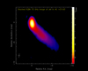 |
Fig. 3. 15 GHz map of 2201+315 provided in the MOJAVE survey. |
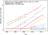 |
Fig. 4. Stationary components C3 and C9 added to the plot of separation vs. time provided in the MOJAVE survey (Lister et al. 2019). |
Radio source 2201+3152 is associated with a quasar whose active galactic nucleus (AGN) class is low-spectral peak < 1014 Hz (LSP), and it is a quasar whose fractional linear optical polarization is consistently below 3% (LQP). Its redshift is z ≈ 0.2947 according to Ho & Kim (2009). Hutchings & Morris (1995) reported that Canada France Hawaii Telescope (CFHT) 3.6 m optical telescope images of 2201+315 indicated an overall elliptical shape, extended normal to the radio axis, but with a radial color gradient (redder with increasing distance), and some irregular knots within the host galaxy. The total magnitudes (R15.6 and V16.6) are close to those quoted in Hewitt & Burbidge (1993) and Hutchings & Neff (1992), and the small differences are probably due to differing extensions of the host galaxy that were measured. Healey et al. (2008) reported an Rmag of MR ≈ 14.33. The Gaia DR2 catalog (Brown et al. 2018) gives a Gmag of 15.3969, a GBPmag of 15.4428, and a GRPmag of 14.9321 (Brown et al. 2018). Gmag (wavelength range 330–1050 nm), GBPmag (blue photometer, wavelength range 330–680 nm) and GRPmag (red photometer, wavelength range 640–1050 nm) are Gaia magnitudes defined in Carrasco et al. (2016). The source has also been detected by the Fermi/LAT – γ-ray space telescope (Acero et al. 2015). It is a strong X-ray AGN observed by Swift (Maselli et al. 2010).
2.3. Stationary component C3
The stationary component C3 is detected at 15 GHz between 1995 and 2011 (Lister et al. 2019). The mean position of C3 is XC3 = −0.288 ± 0.055 mas and YC3 = −0.477 ± 0.111 mas (see Fig. 1), and the distance between cores C0 and C3 is RC3 − C0 = 0.557 ± 0.124 mas (see Fig. 4). The flux density of C3 at 15 GHz is variable, but weaker than or equal to the flux density of the core (see Fig. 10). We show that component C3 is responsible for the ejection of component C7.
2.4. Stationary component C9
The stationary component C9 has been identified and observed between 2009 and 2011 (Lister et al. 2019). However, the identification of the first points of other components indicates that the first two points of component C10, the first three points of component C15, and component C16, which are located at the same position as component C9, are probably associated with component C9 (see Figs. 4 and 5). This means that component C9 is detected between 2009 and 2017.
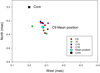 |
Fig. 5. Stationary component C9, identified and observed between 2009 and 2011 (Lister et al. 2019). However, identification of the first points of other components indicates that the two first points of component C10, the three first points of component C15, and component C16, which are located at the same position as component C9, are probably associated with component C9. |
The mean position of C9 is XC9 = −0.082 ± 0.025 mas and YC9 = −0.284 ± 0.061 mas (see Figs. 1 and 5) and the distance between cores C0 and C9 should be RC0 − C9 = 0.296 ± 0.066 mas. However, the error on the distance between cores C0 and C9 is not symmetrical because of the condition Rdisk, C0 < DL1 − C0 (see Eq. (3) and Appendix B.2.1), and we adopt  mas (see Fig. 4) for the distance between the core and C9. A better determination of the distance between C0 and C9 and its error bars could be achieved during the fit of component C6 (see Appendix B.2.1), but this is beyond the scope of this article. Its flux density at 15 GHz is variable but often higher than the flux density of the core (see Fig. 12). It is detected at 15 GHz between 2009 and 2017.
We show that component C13 is ejected from the stationary component C9. Components C10, C15, and C17 are probably also ejected by the BH associated with component C9.
2.5. Components used to fit the model
We fit the precession model and the BBH model parameters using components C6, C7, and C13, that is, components that on the one hand, have enough observed points to have a well-defined trajectory, and on the other hand, have observed points in the first two or three mas to precisely define the origin of the component. We therefore did not fit components C1, C2, and C4, which have no observations in the first 3 mas (C1) and in the first 2 mas (C2 and C4). Component C5, which has a poorly defined trajectory, has not been fit either.
The observations at 15 GHz that we used for this study correspond to 37 epochs and are reported in Table 3 of Lister et al. (2019). We used the model fit data of Lister et al. (2019) to fit the coordinates X(t) and Y(t) of components C6, C7, and C13 using the precession and the BBH model. The results of the fits of components C6, C13, and C7 are given in Sects. 3.4, 3.5, and 3.6, respectively. The positions of the stationary components C0, C9, and C3, the positions of the moving components C6, C7, and C13, and the trajectories obtained from the fit of the BBH system are shown in Fig. 7.
3. Structure of the nucleus of 2201+315
3.1. Stability condition
We describe an important constraint that can be used to fit an ejected VLBI component below. To obtain a stable solution in a BBH system, for instance, the BBH system C0–C9 (see Fig. 1), the radii of the accretion disks around C0 and C9, that is, Rdisk, C0 and Rdisk, C9, must be smaller than the distances DL1 − C0 and DL1 − C9, respectively. Here L1 is the first Lagrange point of the BBH system (the point where the gravitation forces of C0 and C9 are equal).
Calling Tb the orbital period and Tp the precession period of the accretion disk, we can calculate the mass of the ejecting BH MC0, Tb, and Tp for each value of Va the propagation speed of the perturbation along the jet and the beam based on the knowledge of the mass ratio MC0/MC9 and the ratio Tp/Tb.
The rotation period of the accretion disk around C0, Tdisk, C0, is given by (Britzen et al. 2001)
 (1)
(1)
When we assume that the mass of the accretion disk is Mdisk, C0 ≪ MC0, the radius of the accretion disk Rdisk, C0 is
 (2)
(2)
and we must have the stability condition
 (3)
(3)
where DL1 − C0 is the distance between C0 and the first Lagrange point L1, and RC0 − C9 is the separation of the BBH system C0–C9.
The radius of the accretion disk does not depend on Va, which is the propagation speed of the perturbation along the beam and the jet.
3.2. Separation of the BBH systems
At the VLBI core, the VLBI jet becomes transparent to a given synchrotron frequency. The position of the VLBI core does not correspond to the position of the supermassive BH (SMBH), and the distance between the VLBI core and the SMBH depends on the observational frequency. At higher frequency, the VLBI core is closer to the SMBH; see, for instance, Marscher et al. (2008). Although the exact dependence of the distance of the VLBI core to the SMBH with the frequency of observation is not known, the distance between the two VLBI cores that are detected at the same frequency provides a good estimate of the distance between the two SMBH when the ejection directions of the VLBI jets are equal to within few degrees (see Fig. 6). This effect will produce an additional error on the distance determination of the two BH. If the distance between the core and the BH is about 25 μas and the angle between the two jets is 3°, the additional error is ≈ 2 × 25 × sin(3°) = 2.6 μas. When the jets are ejected in opposite directions or in very different directions, the distance between the two VLBI cores is very different than the distance between the two SMBH (see Fig. 6).
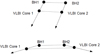 |
Fig. 6. Top: the distance between the two VLBI cores that are detected at the same frequency provides a good estimate of the distance between the two SMBH, BH1 and BH2, if ejection directions of the VLBI jets are equal to within few degrees. Bottom: when the jets are ejected in opposite directions or in very different directions, then the distance between the two VLBI cores is very different than the distance between the two SMBH. |
3.3. Parameter ranges we explored for the fit
In this section, we provide the parameter ranges we explored to fit the VLBI components C6, C7, and C13. In order to cover a wide range of possible inclination angles, we explored the range 2° ≤io ≤ 40°. For the mass ratio of the BBH system, we explored the range 10−7 ≤ M1/M2 ≤ 10, where M1 is the mass of the BH ejecting the VLBI component. For the ratio Tp/Tb, we explored the range 1 ≤ Tp/Tb ≤ 104. For the propagation speed of the perturbation, we explored the range 0.001 c ≤ Va ≤ 0.45 c (we limit ourselves to nonrelativistic hydrodynamics in this model).
3.4. Fit of component C6
3.4.1. Introduction
We studied the three different models given in Table 2. We calculated the curve χ2(io), which corresponds to the χ2 of the model of the VLBI component ejection for a given inclination angle io. The details of the calculations corresponding to the three models are given in Appendix B. In this section, we present the results of fitting the ejection of component C6 from the origin C0 by the BBH system C0–C9.
Different models investigated to fit C6.
We found that component C6 cannot be ejected by a single spinning BH but must be ejected by a BBH system.
3.4.2. BBH system C0–C9 : Origin C0
The BBH system is constituted by core C0 and the stationary component C9. Its separation is RC0 − C9 = 0.3 mas. Component C6 is ejected by the VLBI core, that is, component C0 (see Fig. 7).
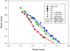 |
Fig. 7. Nucleus of 2201+315 with its three BHs. They are associated with the core, i.e., component C0, and the stationary components C9 and C3. The VLBI components C6, C13, and C7 are ejected from the BHs C0, C9, and C3, respectively. We show the component positions provided by Lister et al. (2019) and the trajectories calculated using the BBH model. |
We found that the mass ratio MC0/MC9 is 0.1 ≤ MC0/MC9 < 1 (see Fig. B.3). Using the stability condition, Rdisk, C0< D(L1 − C0), we found that solutions with the mass ratio MC0/MC9 ≥ 0.6 have Rdisk, C0 ≥ D(L1 − C0) and do not correspond to stable solutions. Moreover, the solution with MC0/MC9 ≈ 0.5 has the smallest  . Thus, component C6 is ejected from core C0 of the BBH system C0–C9, which is characterized by RC0 − C9 ≈ 0.3 mas and MC0/MC9 ≈ 0.5.
The corresponding solution is characterized by  , the inclination angle is io ≈ 6.7°, the ratio Tp/Tb is ≈5.5, and the angle between the accretion disk and the rotation plane of the BBH system is Ω(C0) ≈ 3.1°. The bulk Lorentz factor of the VLBI component is γc ≈ 9.6, and the mean apparent speed is Vap(C6) ≈ 8 c. The ejection time of the VLBI component is to ≈ 2002.4.
Using the parameters of the solution, we gradually varied Va between 0.001 c and 0.45 c. The function χ2(Va) remained constant, indicating a degeneracy of the solution (see Fig. B.6). We deduced the variation range of the C0–C9 parameters in the BBH system that eject C6. They are given in Table 3.
Parameter ranges for the BBH system that ejects C6.
Based on the knowledge of the mass ratio MC0/MC9 and the ratio Tp/Tb, we calculated the mass of the ejecting BH MC0, the orbital period Tb, and the precession period Tp for each value of Va. We found that the radius of the accretion disk around C0 does not depend on Va and is Rdisk, C0 = 0.106 mas = 0.46 pc. The ratio Rdisk, C0/RC0 − L1 is Rdisk, C0/RC0 − L1 = 0.85.
3.5. Fit of component C13
3.5.1. Introduction
We studied the four different cases given in Table 4. We calculated the curve χ2(io), which corresponds to the χ2 of the model of the VLBI component ejection for a given inclination angle io. Details of the calculations corresponding to the four models are given in Appendix C. In this section, we present the results of fitting the ejection of component C13 from the origin C9 by the BBH system C0–C9.
Different models investigated for the fit of C13.
3.5.2. BBH system C0–C9 : Origin C9
The BBH system is constituted by core C0 and the stationary component C9. Its separation is RC0 − C9 = 0.3 mas. Component C13 is ejected by the stationary component C9 (see Fig. 7).
We found that the mass ratio MC9/MC0 is MC9/MC0 > 1 (see Fig. C.5). Using the stability condition, Rdisk, C9 < D(L1 − C9), we found that solutions with the mass ratio MC9/MC0 ≥ 3 have Rdisk, C9 ≥ D(L1 − C9) and do not correspond to stable solutions. Moreover, the solution with MC9/MC0 = 2 has the smallest  . Thus, component C13 is ejected from the stationary component C9 of the BBH system C0–C9, which is characterized by RC0 − C9 = 0.3 mas and MC9/MC0 = 2 ± 0.5. The fit of component C13 ejected from the stationary component C9 provides the mass ratio inverse of the mass ratio provided by the fit of component C6 ejected from core C0. This showis that the BBH model is consistent.
The corresponding solution is characterized by  , and the inclination angle is io ≈ 5.8°. The ratio Tp/Tb is ≈10.2, and the angle between the accretion disk and the rotation plane of the BBH system is Ω(C9)≈3.3°. The bulk Lorentz factor of the VLBI component is γc ≈ 7.3, and the mean apparent speed is Vap(C6) ≈ 6 c. The ejection time of the VLBI component is to ≈ 2011.6.
Using the parameters of the solution, we gradually varied Va between 0.001 c and 0.45 c. The function χ2(Va) remained constant, indicating a degeneracy of the solution (see Fig. C.8). We deduced the range of variation of the BBH system parameters ejecting C13. They are given in Table 5.
Parameter ranges for the BBH system that ejects C13.
We found that component C13 cannot be ejected by a single spinning BH but must be ejected by a BBH system.
We found that the radius of the accretion disk around C9 does not depend on Va and is Rdisk, C9 = 0.140 mas = 0.61 pc. The ratio Rdisk, C9/RC9 − L1 is Rdisk, C9/RC9 − L1 = 0.79.
3.6. Fit of component C7
3.6.1. Introduction
We studied the three different models given in Table 6. We calculated the curve χ2(io), which corresponds to the χ2 of the model of the VLBI component ejection for a given inclination angle io. The details of the calculations corresponding to the three models are given in Appendix D. In this section, we present the results of fitting the ejection of component C7 from the origin C3 by the BBH system (C0+C9)–C3.
Different models investigated for the fit of C7.
We found that component C7 cannot be ejected by a single spinning BH but must be ejected by a BBH system.
3.6.2. BBH system (C0+C9)–C3 : Origin C3
The BBH system is constituted by the system C0+C9 and the stationary component C3. Its separation is RG − C3 = 0.37 mas (see Fig. 1). Component C7 is ejected from the stationary component C3 (see Fig. 7).
We found that the mass ratio MC3/(MC0 + MC9) is MC3/(MC0 + MC9)≤0.1 (see Fig. D.1). We found that solutions with the mass ratio MC3/(MC0 + MC9) < 0.05 have a minimum, but solutions with MC3/(MC0 + MC9) ≥ 0.05 do not have a minimum because when io becomes smaller than about 4.8°, the radius of the accretion disk diverges and becomes larger than the BBH system RG − C3 (see Fig. D.2). We adopted the solution with MC3/(MC0 + MC9) ≈ 0.01, which corresponds to the best solution. Thus, component C7 is ejected from the stationary component C3 of the BBH system (C0+C9)–C3, which is characterized by RG − C3 = 0.37 mas and MC3/(MC0 + MC9) ≈ 0.01.
The corresponding solution is characterized by  , and the inclination angle is io ≈ 6.9°. The ratio Tp/Tb is ≈10.7, and the angle between the accretion disk and the rotation plane of the BBH system is Ω(C0) ≈ 3.8°. The bulk Lorentz factor of the VLBI component is γc ≈ 7.1, and the mean apparent speed is Vap(C7) ≈ 6 c. The ejection time of the VLBI component is to ≈ 2005.4.
Using the parameters of the solution, we gradually varied Va between 0.001 c and 0.45 c. The function χ2(Va) remained constant, indicating a degeneracy of the solution (see Fig. D.3). We deduced the parameter range of variation of the BBH system that ejects C7. They are given in Table 7.
Parameter ranges for the BBH system that ejects C7.
We found that the radius of the accretion disk around C3 does not depend on Va and is Rdisk, C3 = 0.020 mas = 0.09 pc. The ratio Rdisk, C3/RC3 − L1′ is Rdisk, C3/RC3 − L1′ = 0.59, where L1′ is the first Lagrange point of the system (C0+C9)–C3.
3.7. BH system characteristics in 2201+315
The inclination angle of 2201+315 is 5.8° ≤io ≤ 6.9°. The kiloparsec-scale radio map (Cooper et al. 2007) shows two extended lobes, and the total extension of the source is about 75 arcsec. When we assume io ≈ 6.5°, the total extension of the extended lobes is about 2.9 Mpc. The structure of the nucleus is shown in Fig. 1.
To obtain the final range of the parameters of the BH system C9–C0–C3, we intersected the ranges of the BBH system parameters we found after the fits of C13, C6, and C7. The characteristics of the BH system C9–C0–C3 are given in Table 8 where Ω is the angle between the accretion disk and the rotation plane of the BHs.
Characteristics of the BH system, whose components are C9, C0 (core), and C3.
The BH system and the component trajectories of C6, C7, and C13 using the BBH model we obtained in Sects. 3.4, 3.6, and 3.5 are shown in Fig. 7.
4. Discussion and conclusion
The analysis of MOJAVE model fit data with our minimization method suggests that none of components C6, C7, and C13 can be ejected by a single spinning BH, but that they are ejected by BBH systems and that the nucleus of 2201+315 contains three BHs. The three BHs are associated with the VLBI core C0 and the stationary components C9 and C3 as defined by Lister et al. (2019). This source constitutes another example of a nucleus that contains several BHs that are detected in radio and eject VLBI components.
Stationary VLBI components are frequently observed (Jorstad et al. 2017) and are generally assumed to be associated with stationary or recollimation shocks (see Mizuno et al. 2015, Martí et al. 2016, Hada et al. 2018 and references therein), but in the two-fluid model when the relativistic e− − e+ beam dissipates into the subrelativistic e− − p+ jet, a VLBI component is observed that moves subrelativistically. This appears as a quasi stationary VLBI component (see, e.g., component 1 of 1532+016; Lister et al. 2019), and finally the stationary components can also be associated with BHs that eject VLBI components. The stationary components are not necessarily all associated with BHs or with recollimation shocks. To explain the MOJAVE observations of 2201+315, we do not need stationary or recollimation shocks.
As indicated in Roland et al. (2015), a BBH system can produce three perturbations of the VLBI ejection by the precession of the accretion disk, the motion of the two BHs around the center of gravity of the BBH system, and the possible motion of the BBH system around either a third BH or another BBH system. This third perturbation produces a change in the VLBI jet direction of between 5 to 15 mas. It is observed for instance in the cases of 1928+738 (Roland et al. 2015), 3C 345 (Lister et al. 2019), BL Lac (Lister et al. 2019), and 3C 454.3 (Lister et al. 2019).
When we observe a change in VLBI jet direction between 5 to 15 mas, for example, the slow rotation of the BBH system, has to be modeled and the VLBI data have then to be corrected for this slow rotation, so that finally the ejection of the corrected data can be modeled using a BBH system. This has been done by Roland et al. (2015) in the case of 1928+738, which contains two BBH systems. In the case of 2201+315, the mass of the third BH is far lower than that of the two others, and the ejection of components C6 and C13 can be modeled using the BBH system C0–C9 and the ejection of component C7 using the BBH system (C0+C9)–C3.
As indicated in the introduction, when the nucleus contains a BBH system, the two BHs can eject VLBI components and both can be detected using VLBI observations, but it is not necessarily always the case. Roland et al. (2015) showed that 1928+738 contains two BBH systems: the two BHs of the first BBH system are detected (associated with a stationary component) and eject VLBI components; only one BH of the second BBH system ejects VLBI components during the observations; no BH of the second BBH system is associated with a stationary component.
The source 2201+315 has been observed between 1995 and 2018 in the MOJAVE survey. While core C0 is detected during the whole period, component C3 is detected between 1995 and 2010 and component C9 is detected between 2009 and 2017. Because the stationary components C3 and C9 correspond the place in the VLBI jet that becomes transparent to a given synchrotron frequency (see Sect. 3.2), the disappearance of component C3 in 2013 means that at least the ejection of the relativistic e− e+ plasma (the beam) stopped in 2010; this does not mean that the ejection of the subrelativistic e− p plasma (the jet) also stopped in 2010. Component C9 started to be detected in 2009, which means that the ejection of the relativistic e− e+ plasma (the beam) started in 2010.
Source 2201+315 has been observed at 43 and 86 GHz by Cheng et al. (2018). They detected three components J1, J2, and J3. Their positions are shown in Fig. 8. Component J1 probably belongs to the family of trajectories defined by C13 and has been ejected from the stationary component C9. It is just as probable that component J3 belongs to the family of trajectories defined by C6 and has been ejected from core C0 or is ejected from the stationary component C3. For component J2, the situation is less clear because of the shift that is observed with the family of trajectories defined by C13, but it can probably be associated with the family of trajectories defined by C13 and has been ejected from the stationary component C9.
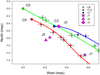 |
Fig. 8. Positions of components J1, J2, and J3 detected at 43 and 86 GHz by Cheng et al. (2018). The VLBI components C6, C13, and C7 are shown. |
An interesting corollary of our study resides in the importance of detecting and separating possible stationary components and determining their flux density ratios, and thereby explaining the position variations measured during geodetic VLBI sessions. Radio source 2201+315 has been intensively observed in the framework of the permanent geodetic VLBI program devoted to absolute astrometry (Fey et al. 2015). In geodetic VLBI analysis, the coordinates of the “radio center” can be estimated on average over observing sessions of 24 h each, and session-wise coordinate time series can be obtained in this way. The radio center is not located at the brightest component of the radio source but can rather be seen as a barycenter of the brightness distribution mitigated by the effect of the network geometry. The accuracy of coordinates as determined by geodetic VLBI is typically a few dozen microarcseconds. This allows recording signatures of subtle changes in the source structure as small variations in the coordinates. Radio source 2201+315 was observed in more than 1000 sessions since 1979, mainly between 1990 and 2010. In Fig. 9 each dot represents the position of the radio center determined in one session of 24 h (see Gattano et al. 2018, for more details). During some periods, dramatic changes in the coordinate time series can be observed. These variations can be explained by two types of variability that occur in the nucleus, that is, the ejection of a new VLBI component whose flux density can be higher than the flux densities of the two stationary components, and in the case of a BBH, the variations in the ratio of the flux densities of the VLBI components associated with two BHs.
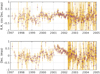 |
Fig. 9. Coordinate time series of 2201+315 (here restricted to 1997–2005) obtained after the analysis of geodetic VLBI data. The position is given as offsets on the local plane of the sky from the average position of the source on the whole observation period of geodetic VLBI (1979–2018). Dots and gray bars show the estimated positions and their uncertainties for each of these sessions. The weighted rms are 0.24 mas in α cos δ and 0.34 mas in δ. |
It is generally observed that changes in astrometric position correspond to the direction of the VLBI jet (Moór et al. 2011). However, if the direction of the BBH system is different from the direction of the VLBI jet, these two types of variations will produce changes in astrometric position in two different directions. During 1997–2005, only components C0 and C3 of the three stationary components were detected. The flux densities of the two component change with time. Generally, the flux density of the core, Sν(C0), is higher than the flux density of component C3, Sν(C3). However, the flux densities of the core and C3 can change rapidly and significantly, and consequently, there are periods where the ratio Sν(C0)/Sν(C3) can be Sν(C0)/Sν(C3) ≈ 1. In 1998–1999, the flux density of the core was similar to the flux density of C3, and the flux density of the nucleus was dominated by the flux density of component C5, which was close to C3 (see Figs. 10 and 11). Thus the mean astrometric position deduced at 8 GHz is shifted to the south. Between 2001 and 2002, the flux density of the nucleus was dominated by the flux density of the core, C0, which increased with time, and the mean astrometric position deduced at 8 GHz is shifted to the north. However, in 2003, the flux density of the core, C0, was similar to the flux density of C3 and the flux density of the nucleus was dominated by the flux density of component C6, which was close to C3 (see Figs. 10 and 11). Thus the mean position deduced at 8 GHz is shifted to the south and we observe a quick change in the astrometric position time series. During the periods 2009 to 2012 and 2014 to 2015, the flux density of component C9 was higher than the flux density of the core (see Fig. 12). During these periods, the astrometric position is shifted along the direction C0–C9, which is different from the VLBI jet direction. Thus the astrometric position of 2201+315 moves with time in two different directions. The mean astrometric position of 2201+315 is located between the stationary components C0, C9, and C3 and does not correspond to any of their positions.
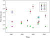 |
Fig. 10. Flux densites of core C0, the second BH, C3, and the flux densities of components C4, C5, and C6 when they were close to the BBH system during the period 1997–2005. The flux densities are taken from Lister et al. (2019). |
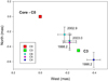 |
Fig. 11. Positions of components C4, C5, and C6 in 1998.2 and ≈2003. The VLBI coordinates are taken from Lister et al. (2019). |
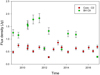 |
Fig. 12. Flux densities of the core and component C9. The flux density of component C9 is higher than the flux density of the core during the periods 2009 to 2012 and 2014 to 2015. The flux densites are taken from Lister et al. (2019). |
This result shows the importance of determining the structure of nuclei of extragalactic radio sources and especially of quasars using VLBI observations at frequencies ≥15 GHz in order to detect and separate possible stationary components and to determine their flux density ratio. This will allow explaining the time shifts of the position observed during geodetic VLBI observations and Gaia observations. This also shows the importance of large MOJAVE-like VLBI databases for improving the understanding of the apparent displacement of the radio center measured by geodetic VLBI and thereby in the maintenance of the celestial reference frames.
See details at http://www.physics.purdue.edu/astro/MOJAVE
Also known as 4C+31.63, B2 2201+31A, J220314.9+314538, or CGRaBS J2203+3145.
Acknowledgments
We thank Prof. Lister who provided us with the new MOJAVE data before publication. We are also grateful to an anonymous referee whose comments helped in improving this work. This research has made use of data from the MOJAVE database that is maintained by the MOJAVE team (Lister et al. 2019).
References
- Acero, F., Ackermann, M., Ajello, M., et al. 2015, ApJS, 218, 23 [Google Scholar]
- Begelman, M. C., Blandford, R. D., & Rees, M. J. 1980, Nature, 287, 307 [NASA ADS] [CrossRef] [Google Scholar]
- Britzen, S., Roland, J., Laskar, J., et al. 2001, A&A, 374, 784 [Google Scholar]
- Brown, A. G. A., Vallenari, A., Prusti, T., et al. 2018, A&A, 616, A1 [NASA ADS] [CrossRef] [EDP Sciences] [Google Scholar]
- Carrasco, J. M., Evans, D. W., Montegriffo, P., et al. 2016, A&A, 595, A7 [NASA ADS] [CrossRef] [EDP Sciences] [Google Scholar]
- Cheng, X. P., An, T., Hong, X. Y., et al. 2018, ApJS, 234, 17 [NASA ADS] [CrossRef] [Google Scholar]
- Colpi, M. 2014, Space Sci. Rev., 183, 189 [NASA ADS] [CrossRef] [Google Scholar]
- Colpi, M., & Dotti, M. 2011, Adv. Sci. Lett., 4, 181 [CrossRef] [Google Scholar]
- Cooper, N. J., Lister, M. L., & Kochanczyk, M. D. 2007, ApJS, 171, 376 [NASA ADS] [CrossRef] [Google Scholar]
- Fey, A. L., Gordon, D., Jacobs, C. S., et al. 2015, ApJS, 150, 58 [Google Scholar]
- Gattano, C., Lambert, S. B., & Le Bail, K. 2018, A&A, 618, A80 [NASA ADS] [CrossRef] [EDP Sciences] [Google Scholar]
- Hada, K., Doi, A., Wajima, K., et al. 2018, ApJ, 860, 141 [NASA ADS] [CrossRef] [Google Scholar]
- Healey, S. E., Romani, R. W., Cotter, G., et al. 2008, ApJS, 175, 97 [NASA ADS] [CrossRef] [Google Scholar]
- Hewitt, A., & Burbidge, G. 1993, ApJS, 87, 451 [NASA ADS] [CrossRef] [Google Scholar]
- Ho, L. C., & Kim, M. 2009, ApJS, 184, 398 [NASA ADS] [CrossRef] [Google Scholar]
- Hutchings, J. B., & Neff, S. G. 1992, ApJS, 104, 1 [NASA ADS] [CrossRef] [Google Scholar]
- Hutchings, J. B., & Morris, S. C. 1995, ApJS, 109, 1541 [NASA ADS] [CrossRef] [Google Scholar]
- Jorstad, S. G., Marscher, A. P., Morozova, D. A., et al. 2017, ApJ, 846, 98 [NASA ADS] [CrossRef] [Google Scholar]
- Katz, J. I. 1997, ApJ, 478, 527 [NASA ADS] [CrossRef] [Google Scholar]
- Lister, M. L., Homan, D. C., Hovatta, T., et al. 2019, ApJ, 874, 43 [NASA ADS] [CrossRef] [Google Scholar]
- Lobanov, A. P., & Roland, J. 2005, A&A, 431, 831 [NASA ADS] [CrossRef] [EDP Sciences] [Google Scholar]
- Marscher, A. P., Jorstad, S. G., D’Arcangelo, F. D., et al. 2008, Nature, 452, 966 [NASA ADS] [CrossRef] [PubMed] [Google Scholar]
- Martí, J. M., Perucho, M., & Gómez, J. L. 2016, ApJ, 831, 163 [NASA ADS] [CrossRef] [Google Scholar]
- Maselli, A., Cusumano, G., Massaro, E., et al. 2010, A&A, 520, A47 [NASA ADS] [CrossRef] [EDP Sciences] [Google Scholar]
- Mizuno, Y., Gómez, J. L., Nishikawa, K.-I., et al. 2015, ApJ, 809, 38 [NASA ADS] [CrossRef] [Google Scholar]
- Moór, A., Frey, S., Lambert, S. B., Titov, O. A., & Bakos, J. 2011, ApJS, 141, 178 [NASA ADS] [CrossRef] [Google Scholar]
- Roland, J., Britzen, S., Kudryavtseva, N. A., Witzel, A., & Karouzos, M. 2008, A&A, 483, 125 [NASA ADS] [CrossRef] [EDP Sciences] [Google Scholar]
- Roland, J., Britzen, S., Caproni, A., et al. 2013, A&A, 557, A85 [Google Scholar]
- Roland, J., Britzen, S., Kun, E., et al. 2015, A&A, 578, A86 [NASA ADS] [CrossRef] [EDP Sciences] [Google Scholar]
- Volonteri, M., Bogdanović, T., Dotti, M., & Colpi, M. 2016, IAU Focus Meeting, 29, 285 [Google Scholar]
Appendix A: Model to fit VLBI observations
Before fitting components C6, C7, and C13, we recall the geometry, parameters, and basic equations of the model, which have been developed in Britzen et al. (2001), Lobanov & Roland (2005), and Roland et al. (2008, 2013). Details can be found in Roland et al. (2008, 2013).
A.1. Geometry of the model
We call Ω the angle between the accretion disk and the orbital plane (XOY) of the BBH system. The component is ejected in a cone (the precession cone) with its axis in the Z′OZ plane and its opening angle is Ω. We assumed that the line of sight is in the plane (YOZ) and that it forms an angle io with the axis Z′OZ (see Fig. A.1). The axis η corresponds to the mean ejection direction of the VLBI component projected on a plane perpendicular to the line of sight, so that the plane perpendicular to the line of sight is the plane (ηOX). We call ΔΞ the rotation angle in the plane perpendicular to the line of sight to transform the coordinates η and X into coordinates N (north) and W (west), which are directly comparable with the VLBI observations. We have
 (A.1)
(A.1)
 (A.2)
(A.2)
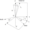 |
Fig. A.1. Geometry of the problem. The planes X – η and west–north are perpendicular to the line of sight. In the west–north plane, the axis η corresponds to the mean ejection direction of the VLBI component. Ω is the opening angle of the precession cone. |
The sign of the coordinate W was changed from Roland et al. (2008) to use the same definition as in the VLBI observations.
A.2. General perturbation of the VLBI ejection
For VLBI observations, the origin of the coordinates is BH 1, that is, the BH that ejects the VLBI components. For the sake of simplicity, we assumed that the two BHs have circular orbits, that is, e = 0. Therefore, the coordinates of the moving components in the frame of reference where BH 1 is considered the ejection origin are (Roland et al. 2008)
![Mathematical equation: $$ \begin{aligned} x_{\rm c}&= [R_{\rm o}(z) \cos (\omega _{\rm p}t-k_{\rm p}z(t)+\phi _{\rm o}) \nonumber \\&\quad + x_{1} \mathrm{cos}(\omega _{\rm b}t-k_{\rm b}z(t)+\psi _{\rm o}) - x_{1} \cos (\psi _{\rm o})] \nonumber \\&\quad ~ \mathrm{exp}(-t/T_{\rm d}), \end{aligned} $$](/articles/aa/full_html/2020/02/aa34740-18/aa34740-18-eq20.gif) (A.3)
(A.3)
![Mathematical equation: $$ \begin{aligned} { y}_{\rm c}&= [R_{\rm o}(z) \sin (\omega _{\rm p}t-k_{\rm p}z(t)+\phi _{\rm o}) \nonumber \\&\quad + { y}_{1} \sin (\omega _{\rm b}t-k_{\rm b}z(t)+\psi _{\rm o}) - { y}_{1} \sin (\psi _{\rm o})] \nonumber \\&\quad ~ \mathrm{exp}(-t/T_{\rm d}), \end{aligned} $$](/articles/aa/full_html/2020/02/aa34740-18/aa34740-18-eq21.gif) (A.4)
(A.4)
 (A.5)
(A.5)
where Ro(z) is the amplitude of the precession perturbation, given by Ro(z) = Rozc(t)/(a + zc(t)), with a = Ro/(2 tanΩ); ωp is ωp = 2π/Tp, where Tp is the precession period, and kp is defined by kp = 2π/TpVa, where Va is the speed of the propagation of the perturbations; ωb is ωb = 2π/Tb, where Tb is the BBH system period and kb is defined by kb = 2π/TbVa; Td is the characteristic time of the damping of the perturbation, and x1 and y1 are given by
![Mathematical equation: $$ \begin{aligned} x_{1} = { y}_{1} = -\frac{ M_{2}}{M_{1}+M_{2}} \times \left[\frac{T_{\rm b}^{2}}{4\pi ^{2}}G(M_{1}+M_{2}) \right]^{1/3}. \end{aligned} $$](/articles/aa/full_html/2020/02/aa34740-18/aa34740-18-eq23.gif) (A.6)
(A.6)
We define with Rbin the distance between the two BHs as the separation of the BBH system. It is
![Mathematical equation: $$ \begin{aligned} R_{\rm bin} = \left[\frac{T_{\rm b}^{2}}{4\pi ^{2}}G(M_{1}+M_{2}) \right]^{1/3}. \end{aligned} $$](/articles/aa/full_html/2020/02/aa34740-18/aa34740-18-eq24.gif) (A.7)
(A.7)
The differential equation governing the evolution of zc(t) can be obtained by defining the speed of the component,
 (A.8)
(A.8)
where vc is related to the bulk Lorentz factor by  .
.
Using Eqs. (A.3), (A.4), and (A.5), we find from Eq. (A.8) that dzc/dt is the solution of equation
 (A.9)
(A.9)
The coefficients A, B, and C are calculated in Appendix A of Roland et al. (2008). Equation (A.9) admits two solutions corresponding to the jet and the counter-jet.
A.3. Coordinates of the VLBI component
Solving Eq. (A.9), we determine the coordinate zc(t) of a point-source component that is ejected relativistically in the perturbed beam. Then, using Eqs. (A.3) and (A.4), we can find the coordinates xc(t) and yc(t) of the component. In addition, for each point of the trajectory, we can calculate the derivatives dxc/dt, dyc/dt, and dzc/dt and then deduce cos θ, δc, Sν, and tobs (see Roland et al. 2013).
After calculating the coordinates xc(t), yc(t), and zc(t), they can be transformed into the wc(t) (west) and nc(t) (north) coordinates using Eqs. (A.1) and (A.2).
As explained in Britzen et al. (2001), Lobanov & Roland (2005), and Roland et al. (2008), the radio VLBI component has to be described as an extended component along the beam. We call nrad the number of points (or integration steps along the beam) for which we integrate to model the component. The coordinates Wc(t) and Nc(t) of the VLBI component are then
 (A.10)
and
 (A.11)
and can be compared with the observed coordinates of the VLBI component, which correspond to the radio peak intensity coordinates provided by model-fitting during the VLBI data reduction process.
A.4. Model parameters
In this section, we list the possible free model parameters. They are: io the inclination angle; ϕo the phase of the precession at t = 0; ΔΞ the rotation angle in the plane perpendicular to the line of sight (see Eqs. (A.1) and (A.2)); Ω the opening angle of the precession cone; Ro the maximum amplitude of the perturbation; Tp the precession period of the accretion disk; Td the characteristic time for the damping of the beam perturbation; M1 the mass of the BH ejecting the radio jet; M2 the mass of the secondary BH; γc the bulk Lorentz factor of the VLBI component; ψo the phase of the BBH system at t = 0; Tb the period of the BBH system; to the time at which the VLBI component is ejected; Va the propagation speed of the perturbations; nrad the number of steps to describe the extension of the VLBI component along the beam; ΔW and ΔN the possible offsets of the origin of the VLBI component.
The parameter nrad is known when the size of the VLBI component is known. In this article we fit components C6, C7, and C13 assuming that their projected size on the sky is = 0.1 mas. This means that practically, the problem we have to solve is a 15 free-parameter problem.
We have to investigate the different possible scenarios with regard to the sense of the rotation of the accretion disk and the sense of the orbital rotation of the BBH system. These possibilities correspond to ±ωp(t − z/Va) and ±ωb(t − z/Va). Because the sense of the precession is always opposite to the sense of the orbital motion (Katz 1997), we study the two cases denoted by +− and −+, where we have ωp(t − z/Va), −ωb(t − z/Va) and −ωp(t − z/Va), ωb(t − z/Va), respectively.
A.5. Method for solving the problem
This method is a practical one that provides solutions, but the method is not unique and does not guarantee that all possible solutions are found. We calculate the projected trajectory on the plane of the sky of an ejected component and determine the parameters of the model to simultaneously produce the best fit with the observed west and north coordinates. The parameters we found minimize
 (A.12)
where χ2(Wc(t)) and χ2(Nc(t)) are the χ2 calculated by comparing the VLBI observations with the calculated coordinates Wc(t) and Nc(t) of the component. For instance, to determine the inclination angle that provides the best fit, we minimize  .
.
The concave parts of the surface χ2(io) contain a minimum. We can find solutions without a minimum; they correspond to the convex parts of the surface χ2(io) and are called mirage solutions.
To illustrate the properties of the surface χ2(io), we plot in Fig. A.2 a possible example of a profile of the solution χ2(io). Figure A.2 shows two possible solutions for which χ2(Sol1)≈χ2(Sol2). Solution 2 is more robust than solution 1, that is, it is the deepest one, and we adopted this solution.
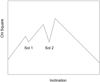 |
Fig. A.2. Example of a possible profile of the solution χ2(io). There are two possible solutions for which χ2(Sol1)≈χ2(Sol2). They correspond to the concave parts of the surface χ2(io). However, solution 2 is more robust than solution 1, i.e., it is the deepest one, and we adopted this solution. |
We define the robustness of the solution as the square root of the difference between the smallest maximum close to the minimum and the minimum of the function χ2. A solution of robustness 3 is a 3 σ solution, that is, 3 σ ⇔ Δχ2 = 9.
The main difficulties we have to solve are the following: to find all possible solutions, to eliminate the mirage solutions, to find the most robust solutions.
One parameter allows us to determine the possible solutions. This fundamental parameter is the ratio Tp/Tb, where Tp and Tb are the precession period of the accretion disk and the binary period of the BBH system, respectively.
To find the possible solutions, for a given inclination angle and for several values of Tp/Tb (say Tp/Tb = 10, 30, 100...), we calculate the function χ2(M1/M2), for 10−7 ≤ M1/M2 ≤ 100 in a first step, and then for a given value of M1/M2 determined previously, we calculate χ2(Tp/Tb) for 1 ≤ Tp/Tb ≤ 10 000. The determination of M1/M2 does not depend on the choice of the inclination angle. Because we investigate a wide range for the parameters M1/M2 and Tp/Tb, we expect to be able to find all possible solutions.
In a second step, for different values of M1/M2 found previously, assuming that Tp/Tb is a free parameter, we calculate χ2(io). When the solution is found, it is not unique, but is a family of solutions. The solution shows a degeneracy, and we show below that the parameter for studying the degeneracy, that is, to find the range of parameters that provide the family of solutions, is Va, the propagation speed of the perturbation along the beam.
Generally, for any value of the parameters, the surface χ2(λ), where λ can be any of the free parameters of the system, io, M1/M2, or Tp/Tb, for instance. is convex and does not present a minimum. Moreover, when we are in the convex part of the surface χ2(λ), one of the important parameters of the problem can diverge. The important parameters of the problem that can diverge are: the bulk Lorentz factor of the e± beam, which has to be γc ≤ 30. This limit is imposed by the stability criterion for the propagation of the relativistic beam in the subrelativistic e−−p jet; the radius of the accretion disk, which has to be smaller than the distance between the distance between the BH and the first Lagrange point (see Sect. 3.1); the ratio Tp/Tb, which has to be > 1, when Tp/Tb = 1 the radius of the accretion disk becomes equal to the separation of the BBH system; and the total mass of the BBH system.
Appendix B: Fit of component C6
We studied the three different models given in Table 2. We calculated the curves χ2(io), which corresponds to the χ2 of the model of the ejection of the VLBI component for a given inclination angle io.
B.1. Precession model: Origin C0
In this section we model the ejection of the VLBI component C6 assuming a single spinning BH, that the VLBI ejection is perturbed by the precession of the accretion disk, and that the ejection origin is core C0. The direction for the precession rotation is chosen to be +.
We found that the possible range for the inclination angle is limited to 2° ≤ io ≤ 11.6°. The bulk Lorentz factor γc exceeds 30 and diverges when io > 11.6°. The curve γc(io) is shown in Fig. B.1.
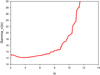 |
Fig. B.1. Precession model. Component C6 is ejected from core C0: the bulk Lorentz factor γc(io). |
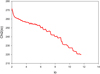 |
Fig. B.2. Precession model. Component C6 is ejected from core C0: the function χ2(io). The curve χ2(io) is convex. |
B.2. BBH C0–C9 model: Origin C0
In this section we model the ejection of the VLBI component C6 assuming a BBH system that consists of core C0 and the stationary component C9. Its separation is RC0 − C9 = 0.3 mas, the VLBI ejection is perturbed by the precession of the accretion disk and the motion of the BHs, and the ejection origin is core C0. The directions for the precession rotation and the BBH rotation are chosen to be + and −, respectively.
Following the method given in Appendix A.5, we calculated the function χ2(MC0/MC9) for io = 8° and Tp/Tb = 10. We found that the mass ratio is 0.1 ≤ MC0/MC9 < 1 (see Fig. B.3), that is, component C6 ejected from core C0 is ejected by the smallest BH of the BBH system C0–C9. It is possible to constrain and determine the mass ratio MC0/MC9 when the radius of the accretion disk around C0, Rdisk, C0 is smaller than the distance DL1 − C0 to obtain a stable solution (see Sect. 3.1 and Eqs. (2) and (3)).
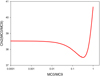 |
Fig. B.3. BBH model C0–C9 characterized by RC0 − C9 = 0.3 mas. Component C6 is ejected from core C0: the function χ2(MC0/MC9). The curve χ2(MC0/MC9) obtained for io = 8° and Tp/Tb = 10. The mass ratio is 0.1 ≤ MC0/MC9 < 1. |
Then we calculated χ2(Tp/Tb) and χ2(io) for various values of MC0/MC9 and found that solutions with MC0/MC9 ≥ 0.6 have Rdisk, C0 ≥ DL1 − C0 and do not correspond to stable solutions. Moreover, we found that for solutions with MC0/MC9 ≤ 0.5 the solution with MC0/MC9 ≈ 0.5 has the smallest  , that is, the solution that provides the best fit of the VLBI component C6 corresponds to the BBH system C0–C9 characterized by RC0 − C9 = 0.3 mas and MC0/MC9 = 0.5. The corresponding solution is characterized by io ≈ 6.7°, Tp/Tb ≈ 5.5 and Ω ≈ 3.1°.
The curves χ2(io) corresponding to the mass ratios MC0/MC9 = 0.1, 0.5 and 0.8 are shown in Fig. B.4. The curves (Rdisk, C0/DL1 − C0)(io) corresponding to the mass ratios MC0/MC9 = 0.1, 0.5 and 0.8 are shown in Fig. B.5.
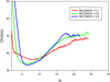 |
Fig. B.4. BBH model C0–C9 characterized by RC0 − C9 = 0.3 mas. Component C6 is ejected from core C0: the functions χ2(io). The curves χ2(io) obtained for different values of the mass ratios MC0/MC9 = 0.1, 0.5 and 0.8. All the curves are concave and show a minimum, but the solution corresponding to MC0/MC9 = 0.8 is not stable because the corresponding ratio (Rdisk, C0/DL1 − C0)(io) is higher than 1 (see Fig. B.5). For solutions with MC0/MC9 ≤ 0.5 the solution with MC0/MC9 ≈ 0.5 has the smallest |

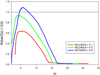 |
Fig. B.5. BBH model C0–C9 characterized by RC0 − C9 = 0.3 mas. Component C6 is ejected from core C0: the functions (Rdisk, C0/DL1 − C0)(io). The curves (Rdisk, C0/DL1 − C0)(io) corresponding to the mass ratios MC0/MC9 = 0.1, 0.5 and 0.8 are shown. Solutions with MC0/MC9 ≥ 0.6 have Rdisk, C0 ≥ DL1 − C0 and do not correspond to stable solutions. |
We found that the curve χ2(io) is convex. It does not have a minimum, that is, there is no stable solution. The curve χ2(io) is shown in Fig. B.2.
B.2.1. Separation of the BBH system C0–C9
We showed in Sect. 2.4 that from the mean position of C9, that is, XC9 = −0.082 ± 0.025 mas and YC9 = −0.284 ± 0.061 mas, the distance between the core C0 and C9 should be RC0 − C9 = 0.296 ± 0.066 mas. However, the solution corresponding to RC0 − C9 = 0.300 mas is characterized by Rdisk, C0/DL1 − C0 = 0.85, and when we reduce RC0 − C9, we will have Rdisk, C0/DL1 − C0 > 1. We found that we must have RC0 − C9 ≥ 0.280 mas, thus the distance between C0 and C9 is  mas, that is, the errors are asymmetrical.
When the solution is known, we can determine the best distance between C0 and C9 and its error. We can choose 30 points, for example, whose positions are close to the C9 position within the errors ΔX = 0.025 mas and ΔY = 0.061 mas. For each point, we calculate its new distance to C0 and the new offset of the VLBI data, and then we calculate the function χ2(io). Then we will be able to deduce the best value of the distance between the two BHs and its error. However, this is beyond the scope of the article.
B.2.2. Solution family
Using the parameters of the solution, we gradually varied Va between 0.001 c and 0.45 c. The function χ2(Va) remained constant, indicating a degeneracy of the solution (see Fig. B.6). The corresponding ranges of the parameters of the BBH system are given in Sect. 3.4.
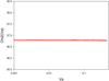 |
Fig. B.6. BBH model C0–C9 characterized by RC0 − C9 = 0.3 mas and MC0/MC9 = 0.5. Component C6 is ejected from the core C0: the function χ2(Va). χ2(Va) remained constant, indicating a degeneracy of the solution. |
B.3. BBH model C0–C3: Origin C0
In this section we model the ejection of the VLBI component C6 assuming the BBH system consists of core C0 and the stationary component C3. Its separation is RC0 − C3 = 0.56 mas, the VLBI ejection is perturbed by the precession of the accretion disk and the motion of the BHs, and the ejection origin is C0. The directions for the precession rotation and the BBH rotation are chosen to be + and −, respectively.
We searched for the solution with RC0 − C3 = 0.56 mas and MC0/MC3 = 0.5 to compare it with the solution found previously in Appendix B.2. The curve χ2(io) is shown in Fig. B.7. It has a minimum, but the corresponding solution has a  larger than the
  of the solution of the fit of C6 assuming it is ejected by the BBH system C0–C9 characterized by RC0 − C9 = 0.3 mas and MC0/MC9 = 0.5 (see Fig. B.4). Moreover, it is a very weak solution, that is, its robustness is ≤1 (see Appendix A.5) and is rejected.
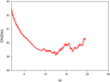 |
Fig. B.7. BBH model C0–C3 characterized by RC0 − C3 ≈ 0.56 mas and MC0/MC3 ≈ 0.5. Component C6 is ejected from core C0: the function χ2(io). The curve χ2(io) has a a minimum, but the corresponding solution has a |


Appendix C: Fit of component C13
We studied the four different cases given in Table 4. We calculated the curves χ2(io).
C.1. Precession model: Origin C0
In this section we model the ejection of the VLBI component C13 assuming a single spinning BH, the VLBI ejection is perturbed by the precession of the accretion disk, and the ejection origine is core C0. The direction for the precession rotation is chosen to be +.
We found that the possible range for the inclination angle is limited to 2° ≤ io ≤ 13.9°. The bulk Lorentz factor γc exceeds 30 and diverges if io > 13.9°. The curve γc(io) is shown in Fig. C.1.
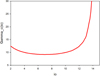 |
Fig. C.1. Precession model. Component C13 is ejected from the core C0: the bulk Lorentz factor γc(io). |
We found that the curve χ2(io) is convex, it does not have a minimum, that is, there is no stable solution. The curve χ2(io) is shown in Fig. C.2.
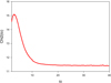 |
Fig. C.2. Precession model. Component C13 is ejected from the core C0: the function χ2(io). The curve χ2(io) is convex, it does not have a minimum, i.e., there is no stable solution. |
C.2. Precession model: origin C9
In this section we mode the ejection of the VLBI component C13 assuming a single spinning BH, the VLBI ejection is perturbed by the precession of the accretion disk, and the ejection origin is the stationary component C9. The direction for the precession rotation is chosen to be +.
We found that the possible range for the inclination angle is limited to 2° ≤io ≤ 14.7°. The bulk Lorentz factor γc exceeds 30 and diverges when io > 14.7°. The curve γc(io) is shown in Fig. C.3.
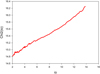 |
Fig. C.3. Precession model. Component C13 is ejected from the stationary component C9: the bulk Lorentz factor γc(io). |
We found that the curve χ2(io) is convex, it does not have a minimum, that is, there is no stable solution. The curve χ2(io) is shown in Fig. C.4.
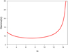 |
Fig. C.4. Precession model. Component C13 is ejected from the stationary component C9: the function χ2(io). The curve χ2(io) is convex, it does not have a minimum, i.e., there is no stable solution. |
C.3. BBH model C0–C9: Origin C9
In this section we model the ejection of the VLBI component C13 assuming that the ejection origin is the stationary component C9 and that it is ejected by the same BBH system that has ejected C6, that is, the BBH system C0–C9, whose separation is RC0 − C9 = 0.3 mas. The VLBI ejection is perturbed by the precession of the accretion disk and the motion of the BHs, and the ejection origin is core C0. The directions for the precession rotation and the BBH rotation are chosen to be + and −, respectively.
First, we calculated the function χ2(MC0/MC9) for io = 8° and Tp/Tb = 10. We found that the mass ratio is MC9/MC0 ≥ 1.0 (see Fig. C.5), that is, component C13 ejected from the stationary component C9 is ejected by the largest BH of the BBH system. It is possible to constrain and determine the mass ratio MC9/MC0 when the radius of the accretion disk around C9, Rdisk, C9 is smaller than the distance DL1 − C9 to obtain a stable solution (see Sect. 3.1).
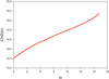 |
Fig. C.5. BBH model C0–C9 characterized by RC0 − C9 ≈ 0.3 mas. Component C13 is ejected from the stationary component C9: the function χ2(MC9/MC0) obtained for io = 8° and Tp/Tb = 10. The mass ratio is MC9/MC0 ≥ 1.0. |
Then we calculated χ2(Tp/Tb) and χ2(io) for various values of the mass ratio MC9/MC0, that is, MC9/MC0 = 1, 2, and 3. The curves corresponding to χ2(io) are shown in Fig. C.6. We found that solutions with MC9/MC0 ≥ 3.0 have Rdisk, C9 ≥ DL1 − C0 and do not correspond to stable solutions. The curves (Rdisk, C9/DL1 − C9)(io) corresponding to the mass ratios MC9/MC0 = 1, 2, and 3 are shown in Fig. C.7. Moreover, we found that for solutions with MC9/MC0 ≤ 2.0 the solution with MC9/MC0 = 2.0 has the smallest  , that is, the solution that provides the best fit of the VLBI component C13 corresponds to the BBH system C0–C9 with RC0 − C9 = 0.3 mas and MC9/MC0 = 2.0 ± 0.5 assuming that component C13 is ejected from the stationary component C9. The solution is characterized by by the inclination angle io ≈ 5.8°, the ratio Tp/Tb ≈ 10.2, and the angle Ω ≈ 3.3°.
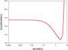 |
Fig. C.6. BBH model C0–C9 characterized by RC0 − C9 = 0.3 mas. Component C13 is ejected from the stationary component C9: the functions χ2(io) obtained for different values of the mass ratios MC9/MC0 = 1, 2 and 3. All the curves are concave and show a minimum, but solutions corresponding to MC9/MC0 ≥ 3 are not stable because the corresponding mass ratios (Rdisk, C9/DL1 − C9)(io) are higher than 1 (see Fig. C.7). |
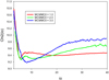 |
Fig. C.7. BBH model C0–C9 characterized by RC0 − C9 = 0.3 mas. Component C13 is ejected from the stationary component C9: the functions (Rdisk, C9/DL1 − C09)(io) corresponding to the mass ratios MC9/MC0 = 1, 2, and 3. Solutions with MC9/MC0 ≥ 3 have Rdisk, C9 ≥ DL1 − C9 and do not correspond to stable solutions. |
Using the parameters of the solution, we gradually varied Va between 0.001 c and 0.45 c. The function χ2(Va) remained constant, indicating a degeneracy of the solution (see Fig. C.8). The corresponding ranges of the parameters of the BBH system are given in Sect. 3.5.
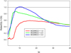 |
Fig. C.8. BBH model C0–C9 characterized by RC0 − C9 = 0.3 mas and MC9/MC0 = 2. Component C13 is ejected from the stationary component C9: the function χ2(Va). χ2(Va) remained constant, indicating a degeneracy of the solution. |
C.4. BBH model C0–C9: Origin C0
In this section we model the ejection of the VLBI component C13 assuming that the ejection origin is core C0 and that it is ejected by the same BBH system that has ejected C6, that is, the BBH system C0–C9, whose separation is RC0 − C9 = 0.3 mas, and the mass ratio is MC0/MC9 = 0.5. The VLBI ejection is perturbed by the precession of the accretion disk and the motion of the BHs, and the ejection origin is core C0. The directions for the precession rotation and the BBH rotation are chosen to be + and −, respectively.
First, we calculated the function χ2(MC0/MC9) for io = 8° and Tp/Tb = 100. We found that the mass ratio is 1.0 ≤ MC0/MC9 ≤ 10 (see Fig. C.9), that is, component C13 ejected from the core is ejected by the largest BH of the BBH system. This result contradicts the result found for the mass ratio MC0/MC9 ≈ 0.5. during the fit of component C6 ejected from the core C0 of the same BBH system C0–C9 (see Appendix B.2). This result shows already that component C13 cannot be ejected from core C0 of the BBH system C0–C9.
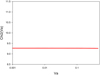 |
Fig. C.9. BBH model C0–C9 characterized by RC0 − C9 ≈ 0.3 mas. Component C13 is ejected from core C0: the function χ2(MC0/MC9) obtained for io = 8° and Tp/Tb = 100. The mass ratio is 1.0 ≤ MC0/MC9 < 10.0. This result shows that component C13 cannot be ejected from core C0 of the BBH system C0–C9. |
However, we calculated χ2(Tp/Tb) and χ2(io) for MC0/MC9 = 0.5 (the value of the mass ratio found during the fit of component C6). The curve χ2(io) corresponding to the mass ratio MC0/MC9 = 0.5 is shown in Fig. C.10. The curve is convex and does not have a minimum, that is, there is no solution, and thus component C13 cannot be ejected from the core C0 of the BBH system C0–C9 characterized by RC0 − C9 = 0.3 mas and the mass ratio MC0/MC9 = 0.5.
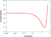 |
Fig. C.10. BBH model C0–C9 characterized by RC0 − C9 = 0.3 mas and the mass ratio MC0/MC9 = 0.5. Component C13 is ejected from the core C0: the function χ2(io). The curve χ2(io) is convex and does not have a minimum, i.e., there is no solution. Thus component C13 cannot be ejected from core C0 of the BBH system C0–C9 characterized by the mass ratio MC0/MC9 = 0.5. |
Appendix D: Fit of component C7
We studied the three different models given in Table 6. We calculated the curves χ2(io).
D.1. Precession model: Origin C0
In this section we model the ejection of the VLBI component C7 assuming a single spinning BH, that the VLBI ejection is perturbed by the precession of the accretion disk, and that the ejection origin is core C0. The direction for the precession rotation is chosen to be +.
We found that the possible range for the inclination angle is limited to 2° ≤ io ≤ 14.4°. The bulk Lorentz factor γc exceeds 30 and diverges when io > 14.4°.
We found that the curve χ2(io) is convex, it does not have a minimum, that is, there is no stable solution. The curve χ2(io) is shown in Fig. D.2.
D.2. BBH model (C0+C9)–C3: Origin C3
In this section we model the ejection of the VLBI component C7 assuming that it is ejected by the BBH system formed by C0+C9 and C3, whose separation is RG − C3 = 0.370 mas (see Fig. 1). The VLBI ejection is perturbed by the precession of the accretion disk and the motion of the BHs, and the ejection origin is component C3. The directions for the precession rotation and the BBH rotation are chosen to be + and −, respectively.
First, we calculated the function χ2(MC0/MC9) for io = 8° and Tp/Tb = 10. The solutions corresponding to the ejection of C7 are characterized by MC3/(MC0 + MC9) ≤ 0.1, that is, the mass of the BH associated with component C3 is far lower than the mass MC0 + MC9 (see Fig. D.1).
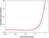 |
Fig. D.1. BBH model (C0+C9)–C3 characterized by RG − C3 = 0.37 mas. Component C7 is ejected from the stationary component C3: the function χ2(MC3/(MC0 + MC9)) obtained for io = 8° and Tp/Tb = 10. The mass ratio MC3/(MC0 + MC9) is MC3/(MC0 + MC9) < 0.1, i.e., the mass of the BH associated with component C3, is far lower than the mass MC0 + MC9. |
Then we calculated the curves χ2(io) corresponding to the separation RG − C3 = 0.37 mas and the mass ratios MC3/(MC0 + MC9) = 0.005, 0.01, 0.05, and 0.1. We found that only solutions with MC3/(MC0 + MC9) < 0.05 are possible and have a minimum (see Fig. D.2). Solutions with MC3/(MC0 + MC9) ≥ 0.05 do not have a minimum, however, and when io becomes smaller than 4.8°, the radius of the accretion disk diverges and becomes larger than the separation of the BBH system (see Fig. D.2).
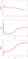 |
Fig. D.2. Top: precession model. Component C7 is ejected from the core C0: the function χ2(io). The curve χ2(io) is convex and it does not have a minimum, i.e., there is no stable solution. Middle: BBH model (C0+C9)–C3 characterized by RG − C3 = 0.37 mas and the mass ratio MC3/(MC0 + MC9) = 0.01. Component C7 is ejected from the component C3: the function χ2(io). The curve χ2(io) has a minimum, |

We adopted the solution with MC3/(MC0 + MC9) = 0.01 and RG − C3 = 0.37 mas, which corresponds to the best solution. The corresponding curve χ2(io) is shown in Fig. D.2. The solution is characterized by an inclination angle io ≈ 6.9°, Tp/Tb ≈ 10.7, and Ω ≈ 3.8°. The value at the minimum  is lower than the value of the minimum of χ2(io) when component C7 is ejected by the BBH system C0–C9 from the core C0 (see Fig. D.4).
Using the parameters of the solution, we gradually varied Va between 0.001 c and 0.45 c. The function χ2(Va) remained constant, indicating a degeneracy of the solution (see Fig. D.3). The corresponding ranges of the parameters of the BBH system are given in Sect. 3.6.
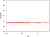 |
Fig. D.3. BBH model (C0+C9)–C3 characterized by R(C0 + C9)−C3 = 0.37 mas and the mass ratio MC3/(MC0 + MC9) = 0.01. Component C7 is ejected from the stationary component C3: the function χ2(Va). χ2(Va) remained constant, indicating a degeneracy of the solution. |
D.3. BBH model C0–C9: origin C0
In this section we model the ejection of the VLBI component C7 assuming that it is ejected by the same BBH system that has ejected C6, that is, the BBH system C9–C0, whose separation is RC0 − C9 = 0.3 mas, and the mass ratio is MC0/MC9 = 0.5. The VLBI ejection is perturbed by the precession of the accretion disk and the motion of the BHs, and the ejection origin is core C0. The directions for the precession rotation and the BBH rotation are chosen to be + and −, respectively.
First, we calculated the function χ2(MC0/MC9) for io = 8° and Tp/Tb = 10. The solutions corresponding to the ejection of C7 are characterized by MC0/MC9 < 1.0.
The curve χ2(io) corresponding to the mass ratio MC0/MC9 = 0.5 is shown in Fig. D.4. The curve χ2(io) has a minimum,  at io ≈ 5.0°. The solution is characterized by Tp/Tb ≈ 9.3 and Ω ≈ 1.2°. These values should be the same as those found for the solution corresponding to the ejection of C6 by C0, that is, (Tp/Tb)C6 ≈ 5.5 and ΩC6 ≈ 3.1°. When C0 ejects different components, they are characterized by the same geometrical parameters Tp/Tb and Ω. This solution is therefore not the correct one and is rejected. Its
  is larger than the
  of the solution obtained for the BBH system (C0+C9)–C3 (see Appendix D.2).
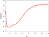 |
Fig. D.4. BBH model C0–C9 characterized by RC0 − C9 = 0.3 mas and the mass ratio MC0/MC9 = 0.5. Component C7 is ejected from the core C0: the function χ2(io). The curve χ2(io) has a minimum, |

All Tables
All Figures
|
Fig. 1. Structure of the nucleus of 2201+315. The analysis of MOJAVE data with our minimization method suggests that the nucleus of 2201+315 contains three BHs. G is the center of gravity of the BBH system C0–C9 and L1 is the first Lagrange point of the BBH system C0–C9; this is the point where the gravitational forces of the BHs C0 and C9 are equal. In order to obtain a stable solution, the radii of the accretion disks around C0 and C9 have to be smaller than the distances L1–C0 and L1–C9, respectively. |
| In the text | |
|
Fig. 2. Two-fluid model. The outflow consists of an e− − e+ plasma, the beam, which moves at a highly relativistic speed and is surrounded by an e− − p plasma, and of the jet, which moves at a mildly relativistic speed. |
| In the text | |
|
Fig. 3. 15 GHz map of 2201+315 provided in the MOJAVE survey. |
| In the text | |
|
Fig. 4. Stationary components C3 and C9 added to the plot of separation vs. time provided in the MOJAVE survey (Lister et al. 2019). |
| In the text | |
|
Fig. 5. Stationary component C9, identified and observed between 2009 and 2011 (Lister et al. 2019). However, identification of the first points of other components indicates that the two first points of component C10, the three first points of component C15, and component C16, which are located at the same position as component C9, are probably associated with component C9. |
| In the text | |
|
Fig. 6. Top: the distance between the two VLBI cores that are detected at the same frequency provides a good estimate of the distance between the two SMBH, BH1 and BH2, if ejection directions of the VLBI jets are equal to within few degrees. Bottom: when the jets are ejected in opposite directions or in very different directions, then the distance between the two VLBI cores is very different than the distance between the two SMBH. |
| In the text | |
|
Fig. 7. Nucleus of 2201+315 with its three BHs. They are associated with the core, i.e., component C0, and the stationary components C9 and C3. The VLBI components C6, C13, and C7 are ejected from the BHs C0, C9, and C3, respectively. We show the component positions provided by Lister et al. (2019) and the trajectories calculated using the BBH model. |
| In the text | |
|
Fig. 8. Positions of components J1, J2, and J3 detected at 43 and 86 GHz by Cheng et al. (2018). The VLBI components C6, C13, and C7 are shown. |
| In the text | |
|
Fig. 9. Coordinate time series of 2201+315 (here restricted to 1997–2005) obtained after the analysis of geodetic VLBI data. The position is given as offsets on the local plane of the sky from the average position of the source on the whole observation period of geodetic VLBI (1979–2018). Dots and gray bars show the estimated positions and their uncertainties for each of these sessions. The weighted rms are 0.24 mas in α cos δ and 0.34 mas in δ. |
| In the text | |
|
Fig. 10. Flux densites of core C0, the second BH, C3, and the flux densities of components C4, C5, and C6 when they were close to the BBH system during the period 1997–2005. The flux densities are taken from Lister et al. (2019). |
| In the text | |
|
Fig. 11. Positions of components C4, C5, and C6 in 1998.2 and ≈2003. The VLBI coordinates are taken from Lister et al. (2019). |
| In the text | |
|
Fig. 12. Flux densities of the core and component C9. The flux density of component C9 is higher than the flux density of the core during the periods 2009 to 2012 and 2014 to 2015. The flux densites are taken from Lister et al. (2019). |
| In the text | |
|
Fig. A.1. Geometry of the problem. The planes X – η and west–north are perpendicular to the line of sight. In the west–north plane, the axis η corresponds to the mean ejection direction of the VLBI component. Ω is the opening angle of the precession cone. |
| In the text | |
|
Fig. A.2. Example of a possible profile of the solution χ2(io). There are two possible solutions for which χ2(Sol1)≈χ2(Sol2). They correspond to the concave parts of the surface χ2(io). However, solution 2 is more robust than solution 1, i.e., it is the deepest one, and we adopted this solution. |
| In the text | |
|
Fig. B.1. Precession model. Component C6 is ejected from core C0: the bulk Lorentz factor γc(io). |
| In the text | |
|
Fig. B.2. Precession model. Component C6 is ejected from core C0: the function χ2(io). The curve χ2(io) is convex. |
| In the text | |
|
Fig. B.3. BBH model C0–C9 characterized by RC0 − C9 = 0.3 mas. Component C6 is ejected from core C0: the function χ2(MC0/MC9). The curve χ2(MC0/MC9) obtained for io = 8° and Tp/Tb = 10. The mass ratio is 0.1 ≤ MC0/MC9 < 1. |
| In the text | |
|
Fig. B.4. BBH model C0–C9 characterized by RC0 − C9 = 0.3 mas. Component C6 is ejected from core C0: the functions χ2(io). The curves χ2(io) obtained for different values of the mass ratios MC0/MC9 = 0.1, 0.5 and 0.8. All the curves are concave and show a minimum, but the solution corresponding to MC0/MC9 = 0.8 is not stable because the corresponding ratio (Rdisk, C0/DL1 − C0)(io) is higher than 1 (see Fig. B.5). For solutions with MC0/MC9 ≤ 0.5 the solution with MC0/MC9 ≈ 0.5 has the smallest |
| In the text | |
|
Fig. B.5. BBH model C0–C9 characterized by RC0 − C9 = 0.3 mas. Component C6 is ejected from core C0: the functions (Rdisk, C0/DL1 − C0)(io). The curves (Rdisk, C0/DL1 − C0)(io) corresponding to the mass ratios MC0/MC9 = 0.1, 0.5 and 0.8 are shown. Solutions with MC0/MC9 ≥ 0.6 have Rdisk, C0 ≥ DL1 − C0 and do not correspond to stable solutions. |
| In the text | |
|
Fig. B.6. BBH model C0–C9 characterized by RC0 − C9 = 0.3 mas and MC0/MC9 = 0.5. Component C6 is ejected from the core C0: the function χ2(Va). χ2(Va) remained constant, indicating a degeneracy of the solution. |
| In the text | |
|
Fig. B.7. BBH model C0–C3 characterized by RC0 − C3 ≈ 0.56 mas and MC0/MC3 ≈ 0.5. Component C6 is ejected from core C0: the function χ2(io). The curve χ2(io) has a a minimum, but the corresponding solution has a |
| In the text | |
|
Fig. C.1. Precession model. Component C13 is ejected from the core C0: the bulk Lorentz factor γc(io). |
| In the text | |
|
Fig. C.2. Precession model. Component C13 is ejected from the core C0: the function χ2(io). The curve χ2(io) is convex, it does not have a minimum, i.e., there is no stable solution. |
| In the text | |
|
Fig. C.3. Precession model. Component C13 is ejected from the stationary component C9: the bulk Lorentz factor γc(io). |
| In the text | |
|
Fig. C.4. Precession model. Component C13 is ejected from the stationary component C9: the function χ2(io). The curve χ2(io) is convex, it does not have a minimum, i.e., there is no stable solution. |
| In the text | |
|
Fig. C.5. BBH model C0–C9 characterized by RC0 − C9 ≈ 0.3 mas. Component C13 is ejected from the stationary component C9: the function χ2(MC9/MC0) obtained for io = 8° and Tp/Tb = 10. The mass ratio is MC9/MC0 ≥ 1.0. |
| In the text | |
|
Fig. C.6. BBH model C0–C9 characterized by RC0 − C9 = 0.3 mas. Component C13 is ejected from the stationary component C9: the functions χ2(io) obtained for different values of the mass ratios MC9/MC0 = 1, 2 and 3. All the curves are concave and show a minimum, but solutions corresponding to MC9/MC0 ≥ 3 are not stable because the corresponding mass ratios (Rdisk, C9/DL1 − C9)(io) are higher than 1 (see Fig. C.7). |
| In the text | |
|
Fig. C.7. BBH model C0–C9 characterized by RC0 − C9 = 0.3 mas. Component C13 is ejected from the stationary component C9: the functions (Rdisk, C9/DL1 − C09)(io) corresponding to the mass ratios MC9/MC0 = 1, 2, and 3. Solutions with MC9/MC0 ≥ 3 have Rdisk, C9 ≥ DL1 − C9 and do not correspond to stable solutions. |
| In the text | |
|
Fig. C.8. BBH model C0–C9 characterized by RC0 − C9 = 0.3 mas and MC9/MC0 = 2. Component C13 is ejected from the stationary component C9: the function χ2(Va). χ2(Va) remained constant, indicating a degeneracy of the solution. |
| In the text | |
|
Fig. C.9. BBH model C0–C9 characterized by RC0 − C9 ≈ 0.3 mas. Component C13 is ejected from core C0: the function χ2(MC0/MC9) obtained for io = 8° and Tp/Tb = 100. The mass ratio is 1.0 ≤ MC0/MC9 < 10.0. This result shows that component C13 cannot be ejected from core C0 of the BBH system C0–C9. |
| In the text | |
|
Fig. C.10. BBH model C0–C9 characterized by RC0 − C9 = 0.3 mas and the mass ratio MC0/MC9 = 0.5. Component C13 is ejected from the core C0: the function χ2(io). The curve χ2(io) is convex and does not have a minimum, i.e., there is no solution. Thus component C13 cannot be ejected from core C0 of the BBH system C0–C9 characterized by the mass ratio MC0/MC9 = 0.5. |
| In the text | |
|
Fig. D.1. BBH model (C0+C9)–C3 characterized by RG − C3 = 0.37 mas. Component C7 is ejected from the stationary component C3: the function χ2(MC3/(MC0 + MC9)) obtained for io = 8° and Tp/Tb = 10. The mass ratio MC3/(MC0 + MC9) is MC3/(MC0 + MC9) < 0.1, i.e., the mass of the BH associated with component C3, is far lower than the mass MC0 + MC9. |
| In the text | |
|
Fig. D.2. Top: precession model. Component C7 is ejected from the core C0: the function χ2(io). The curve χ2(io) is convex and it does not have a minimum, i.e., there is no stable solution. Middle: BBH model (C0+C9)–C3 characterized by RG − C3 = 0.37 mas and the mass ratio MC3/(MC0 + MC9) = 0.01. Component C7 is ejected from the component C3: the function χ2(io). The curve χ2(io) has a minimum, |
| In the text | |
|
Fig. D.3. BBH model (C0+C9)–C3 characterized by R(C0 + C9)−C3 = 0.37 mas and the mass ratio MC3/(MC0 + MC9) = 0.01. Component C7 is ejected from the stationary component C3: the function χ2(Va). χ2(Va) remained constant, indicating a degeneracy of the solution. |
| In the text | |
|
Fig. D.4. BBH model C0–C9 characterized by RC0 − C9 = 0.3 mas and the mass ratio MC0/MC9 = 0.5. Component C7 is ejected from the core C0: the function χ2(io). The curve χ2(io) has a minimum, |
| In the text | |
Current usage metrics show cumulative count of Article Views (full-text article views including HTML views, PDF and ePub downloads, according to the available data) and Abstracts Views on Vision4Press platform.
Data correspond to usage on the plateform after 2015. The current usage metrics is available 48-96 hours after online publication and is updated daily on week days.
Initial download of the metrics may take a while.