Fig. 10
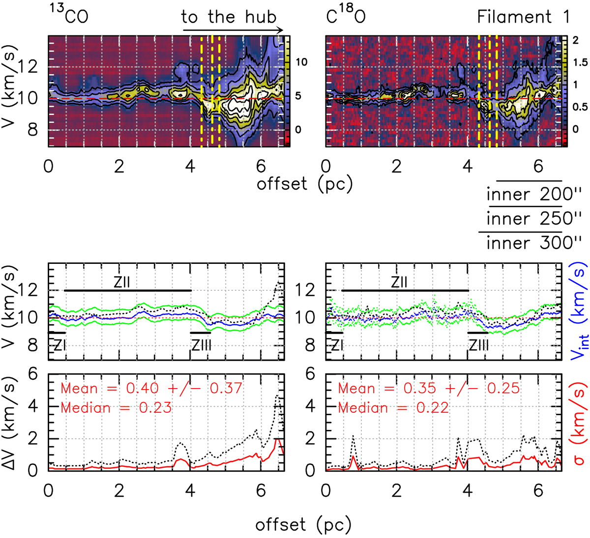
Position-velocity diagrams (top panels) along the skeleton of filament F1 obtained from the 13CO (left) and C18O (right) data cubes. The vertical yellow dashed lines indicate the transition between the hub and the filaments, corresponding to radii 200′′, 250′′ (Rhub), and 300′′. Middle panels: variation in velocity against the offset along the filament in two different manners. The dotted black line corresponds to the velocity obtained at the central pixel that constitutes the skeleton of the filament, while the blue line shows the velocity along the skeleton after averaging over the velocity range shown in the top panels. The green lines indicate the velocity range where most of the emission of the filament resides. Bottom panels: line-width (Δv) of the skeleton’s central pixels along the filaments (in black) and the velocity dispersion calculated from
![]() (in red). The text labels show the mean and the median value of the velocity dispersion.
(in red). The text labels show the mean and the median value of the velocity dispersion.
Current usage metrics show cumulative count of Article Views (full-text article views including HTML views, PDF and ePub downloads, according to the available data) and Abstracts Views on Vision4Press platform.
Data correspond to usage on the plateform after 2015. The current usage metrics is available 48-96 hours after online publication and is updated daily on week days.
Initial download of the metrics may take a while.