Fig. 5
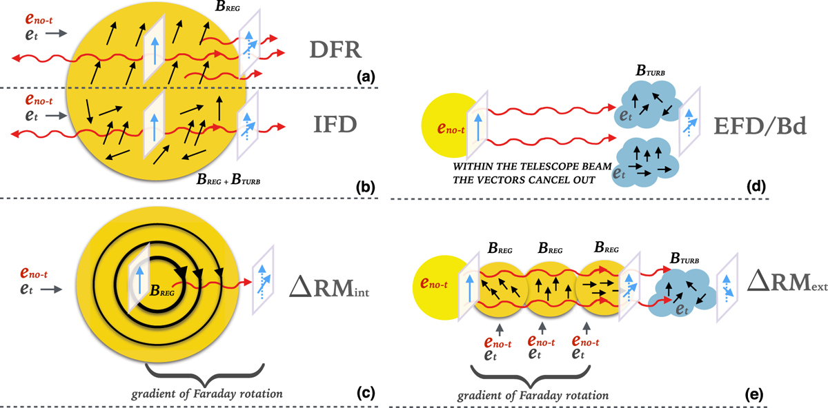
Depolarization mechanisms. The red undulated arrows represent the synchrotron radiation and the blue arrows represent the polarization vector of the radiation; the length of this vector decreases when depolarization occurs. The black arrows represent the magnetic field direction and its intensity is represented by the thickness of the arrows. The pictures (a), (b), and (c) represent the cases of internal depolarization where the synchrotron-emitting regions and the Faraday rotating regions coexist together (dark yellow with thermal, et , and nonthermal, eno-t, electrons). Picture (a) represents the DFR (Eq. (11)) where a regular magnetic field is present, picture (b) represents the IFD (Eq. (10)) where a turbulent and a regular magnetic field is present, and picture (c) represents the depolarization due to an internal gradient of RM (Δ RM int, Eq. (12)); the magnetic field is uniform and throughout the region the radiation undergoes both fractional polarization and polarization angle smooth changes. Picture (d) represents the case of external depolarization where the synchrotron-emitting region (yellow circle containing eno-t) and the Faraday rotating region (blue cloud containing et) are separated (Eq. (9)). Here the depolarization is due to the presence of a turbulent magnetic field or to the polarized vectors canceling each other out within the telescope beam (beam depolarization, Bd). Picture (e) represents the depolarization due to a gradient of RM due to the presence of a foreground region (Eq. (13)).
Current usage metrics show cumulative count of Article Views (full-text article views including HTML views, PDF and ePub downloads, according to the available data) and Abstracts Views on Vision4Press platform.
Data correspond to usage on the plateform after 2015. The current usage metrics is available 48-96 hours after online publication and is updated daily on week days.
Initial download of the metrics may take a while.