| Issue |
A&A
Volume 582, October 2015
|
|
|---|---|---|
| Article Number | A8 | |
| Number of page(s) | 12 | |
| Section | Catalogs and data | |
| DOI | https://doi.org/10.1051/0004-6361/201526385 | |
| Published online | 29 September 2015 | |
Astrometry of the main satellites of Uranus: 18 years of observations⋆,⋆⋆
1 Observatório Nacional/MCTI, R. General José Cristino 77, CEP 20921-400, Rio de Janeiro, RJ, Brazil
e-mail: This email address is being protected from spambots. You need JavaScript enabled to view it.
2 Laboratório Interinstitucional de e-Astronomia – LIneA, Rua Gal. José Cristino 77, Rio de Janeiro, RJ 20921-400, Brazil
3 Instituto Nacional de Pesquisas Espaciais, Av. dos Astronautas 1758, CEP 12227-010 São José dos Campos, SP, Brazil
4 Affiliated researcher at the Observatoire de Paris/IMCCE, 77 av. Denfert-Rochereau, 75014 Paris, France
5 Observatório do Valongo/UFRJ, Ladeira do Pedro Antônio 43, CEP 20080-090 Rio de Janeiro, RJ, Brazil
6 Associated researcher at the Observatoire de Paris/IMCCE, 77 av. Denfert-Rochereau, 75014 Paris, France
7 Federal University of Technology – Paraná (UTFPR / DAFIS), Rua Sete de Setembro, 3165 CEP 80230-901, Curitiba, PR, Brazil
8 Associated researcher at the Observatoire de Paris/SYRTE, 77 av. Denfert Rochereau, 75014 Paris, France
9 Associated researcher at the INAF/Osservatorio Astronomico di Torino, Strada Osservatorio 20, 10025 Pino Torinesi (To), Italy
10 Centro Universitário Estadual da Zona Oeste, Av. Manual Caldeira de Alvarenga 1203, CEP 23. 070-200 Rio de Janeiro RJ, Brazil
Received: 22 April 2015
Accepted: 24 July 2015
Abstract
Context. We contribute to developing dynamical models of the motions of Uranus’ main satellites.
Aims. We determine accurate positions of the main satellites of Uranus: Miranda, Ariel, Umbriel, Titania, and Oberon. Positions of Uranus, as derived from those of these satellites, are also determined. The observational period spans from 1992 to 2011. All runs were made at the Pico dos Dias Observatory, Brazil.
Methods. We used the software called Platform for Reduction of Astronomical Images Automatically (PRAIA) to perform a digital coronography to minimise the influence of the scattered light of Uranus on the astrometric measurements and to determine accurate positions of the main satellites. The positions of Uranus were then indirectly determined by computing the mean differences between the observed and ephemeris positions of these satellites. A series of numerical filters was applied to filter out spurious data. These filters are mostly based on (a) the comparison between the positions of Oberon with those of the other satellites and on (b) the offsets as given by the differences between the observed and ephemeris positions of all satellites.
Results. We have, for the overall offsets of the five satellites, −29 mas (±63 mas) in right ascension and −27 mas (±46 mas) in declination. For the overall difference between the offsets of Oberon and those of the other satellites, we have +3 mas (±30 mas) in right ascension and −2 mas (±28 mas) in declination. Ephemeris positions for the satellites were determined from DE432+ura111. Comparisons using other modern ephemerides for the solar system – INPOP13c – and for the motion of the satellites – NOE-7-2013 – were also made. They confirm that the largest contribution to the offsets we find comes from the motion of the barycenter of the Uranus system around the barycenter of the solar system, as given by the planetary ephemerides. For the period from 1992 to 2011, our final catalogues contain 584 observed positions of Miranda, 1710 of Ariel, 1987 of Umbriel, 2588 of Titania, 2928 of Oberon, and 3516 of Uranus.
Key words: astrometry / methods: data analysis / catalogs / planets and satellites: individual: Uranus
Based on observations made at the Pico dos Dias Observatory/ LNA.
Tables with the positions of Uranus and its satellites, as well as with the X and Y CCD coordinates of the observed satellites and reference stars are only available at the CDS via anonymous ftp to cdsarc.u-strasbg.fr (130.79.128.5) or via http://cdsarc.u-strasbg.fr/viz-bin/qcat?J/A+A/582/A8
© ESO, 2015
1. Introduction
Accurate positions from gound-based CCD images of small bodies and natural satellites in the solar system are an important tool for developing accurate dynamical models of their motions (Lainey 2008) and to support (see Desmars et al. 2015, for instance) further investigations of these bodies and their surrounding environments by other observational techniques and methods, such as stellar occultations (Braga-Ribas et al. 2014). In addition, the knowledge of the dynamics of natural satellites is important to constrain models of formation and evolution of the solar system (Nogueira et al. 2011), to understand their internal structure (Lainey et al. 2009), and to more general studies of the physics of a particular planetary system (see Jacobson 2014, for the Uranus system).
A summary of ground-based techniques used in the astrometry of solar system bodies, along with their respective accuracies, can be found in Arlot (2008). Stellar occultations can also be included among those techniques since they are also a source of accurate positions (see Person et al. 2006; Sicardy et al. 2006; Widemann et al. 2009; Assafin et al. 2010; Benedetti-Rossi et al. 2014). In the case of Pluto, for instance, one could take advantage of the fact that its photocenter displacement due to the presence of Charon is not of concern for the astrometry from stellar occultations.
Here, we aim at contributing to dynamical models of the motions of the main satellites of Uranus: Miranda, Ariel, Umbriel, Titania, and Oberon. This contribution is made by determining accurate positions determined from CCD observations carried out at the Pico dos Dias Observatory in the period 1992–2011.
Uranus was not directly observed in this work. However, positions of Uranus, indirectly determined from those of the satellites, are also provided since they are relevant to improve its orbit. In fact, orbits in modern planetary ephemerides are not uniformly known. Those of Uranus, Neptune, and Pluto have uncertainties of several thousand kilometers, two orders of magnitude greater than those for Jupiter and Saturn. The situation is even more dramatic when the comparison is made with the inner solar system, where orbits are known to subkilometric accuracy (see Folkner et al. 2014, for further details).
This work represents an extension of that by Veiga et al. (2003, hereafter V03) and follows the efforts of many others that determined optical positions within the system of Uranus from the ground. In addition to traditional astrometry, a noticeable contribution comes also from the observation of mutual events, where Hidas et al. (2008) were the first to report such an analysis to our knowledge that involved the satellites of Uranus. Comprehensive lists of observational sources for the system of Uranus can be found, for instance, in Jacobson (2014) and Emelyanov & Nikonchuk (2013).
Next, in Sect. 2, we describe the site and instruments. Data reduction procedure and the results and analysis are presented in Sects. 3 and 4, respectively. Comparisons with other ephemerides are given in Sect. 5. Section 6 argues the extension of the astrometry of this work to older epochs using results from V03, and Sect. 7 presents our position catalogues. Comments and conclusions are given in Sect. 8.
Characteristics of the telescopes.
2. Site and instruments
All observations were made with three telescopes located at the Pico dos Dias Observatory (IAU code 874, λ = − 45o34′57′′ W, φ = − 22o32′04′′, and h = 1810.7 m), run by the Laboratório Nacional de Astrofísica/MCTI1. Their characteristics are summarised in Table 1. All of them have equatorial mounts.
CCD detectors.
A number of detectors, as given by Table 2, were installed at the telescopes presented in Table 1. Typically, our images from the Perkin-Elmer telescope have a field of view (FOV) of 3′ to 6′, and for the other telescopes, the FOV is 5′ to 11′.
Filters B, V, R, and I, compatible with the Johnsons-Cousins system, were used. Most of our observations, however, were made without filter.
3. Data reduction
All raw images were first corrected for bias and flatfield with IRAF (Tody 1993). Then, a digital coronography procedure (see Assafin et al. 2008, 2009) was applied to minimise the effect of the scattered light from Uranus on the positions of the satellites.
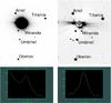 |
Fig. 1 Image containing Uranus and its main satellites, as obtained on 18 July, 1992, with the Perkin-Elmer telescope. Upper left (right) panel: inverted colour map image before (after) the application of the digital coronography procedure. Lower left (right) panel: respective Miranda flux profile along a segment placed on the line joining the centres of Uranus and Miranda. This segment is the same in the two lower panels. Image orientation is north up and east left. Exposure time is 9 s. All other objects in the image that do not belong to the system of Uranus are field stars. |
Figure 1 illustrates the performance of this correction. In this figure, the angular separation between the centres of Uranus and Miranda is 9.5′′. Although the centroid determination of any object contaminated by the scattered light of Uranus profits from the digital coronography, this procedure is evidently more relevant to Miranda in our images.
The final step, that is, the determination of the positions of the satellites of Uranus in all images, was fully implemented with the Platform for Reduction of Astronomical Images Automatically (PRAIA) package2(Assafin et al. 2011).
The results presented here were obtained from the analysis of a total of 4532 images, all telescopes and detectors shown in Tables 1 and 2 included, distributed along 138 nights in the period 1992–2011 (see also Fig. 2). These counts exclude images (23% of the total) where positions, for whatever reason, were not obtained. We used the Fourth US Naval Observatory CCD Astrograph Catalog (UCAC4; Zacharias et al. 2013) as the practical representative of the International Celestial Reference System (ICRS; Arias et al. 1995).
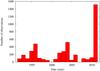 |
Fig. 2 Distribution of the number of observations per year. |
Figure 2 also shows the absence of observations in 2000 and 2007. In 2000, we had no observational runs at the Pico dos Dias Observatory. In 2007, all observations (more than 18 000) of the Uranus system were aimed at determining dynamical parameters from light curves obtained during mutual events among the satellites (see Assafin et al. 2009). As a result of their short exposure times (1–3 s) and small FOV (usually 2′× 2′ or less), they were not used in this work.
4. Results and data analysis
The observed positions of the satellites were first compared to those provided by ephemerides from the JPL: the planetary ephemeris DE432 and ura1113.
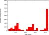 |
Fig. 3 Distribution of the number of observations per year after applying filters 1 to 5. |
By means of the SPICE system toolkits (Acton 1996), DE432 was used to link the geocenter to the barycenter of the Uranus system, whereas ura111 was used to link this latter to the centre of Uranus and those of its main satellites. The link between the geocenter and the topocenter was obtained with subroutines from the Standards of Fundamental Astronomy4 (SOFA) and from the Naval Observatory Vector Astrometry Software5 (NOVAS). The sum of these links (or vectors) produced the astrometric ephemeris positions of Uranus and of its main satellites for an observer at the Pico dos Dias Observatory.
The differences in the sense observed minus ephemeris positions are referred to as offsets in position, following the nomenclature commonly used in astrometric works. These offsets were determined and used to filter out spurious data. Details on this filtering are given below. We note that, except for item 1, no further consideration was made with respect to the telescope, filter, or detector used.
-
1.
All satellite positions whose centres were closer than8′′ (for observations made with the Perkin-Elmer telescope) or 7′′ (for observations made with the Boller&Chivens or Zeiss telescopes) to the centre of Uranus were discarded. This was done to avoid cases where the digital coronography might fail to produce reliable results.
-
2.
All images with astrometry derived from less than five reference (UCAC4) stars were discarded. This was done avoid a poor representation of the celestial frame.
-
3.
For each night and each satellite, an iterative σ-clipping procedure filtered out all those offsets that differed from the mean offset in right ascension or declination by more than 2σ; this way, we eliminated poor measurements.
-
4.
To all observations of a given satellite, an iterative σ-clipping procedure filtered out all those residuals in right ascension and declination, as given by the difference between the offsets of the given satellite and those of Oberon in the same respective images that differed from the mean residual by more than 3σ. This was a coherence check, assuming that the orbits of the satellites around the barycenter of the Uranus system are well known. This is discussed below. Oberon was chosen as reference because its positions were determined in all the 4532 images mentioned earlier and, most relevant, it is the most distant and the slowest among the satellites studied here (as a consequence, Oberon has the most realiable orbit of the satellites studied here).
-
5.
To all observations of a given satellite, an iterative σ-clipping procedure filtered out all those offsets in right ascension and declination that differed from the mean offset by more than 3σ. We did this to use the information from the whole data set to filter out poor representations of the celestial frame that survived item 2 and that can only be identified when a large portion of the sky is considered.
These filters were applied one after the other in the sequence they have just been presented. The most severe of them, that is, the one that eliminated the most, was that described in item 3. The least severe procedure was that described in item 5.
Figure 3 shows the number of observations per year after applying all filters. From comparing Figs. 2 and 3, it is clear that positions derived from observations made after 2000 were more affected by the application of the filters than those made earlier. The reason for this can be easily explained by Fig. 4. After 2000, the planes of the orbits of the satellites were approaching an edge-on view so that observations became more complicated, and in addition, more satellite positions were filtered out because of their proximity to Uranus.
Tables 3 to 7 show yearly offsets for each satellite. Table 3 clearly shows the decrease in the number of positions of Miranda as the plane of its orbit approaches an edge-on view. Figures 5 to 9 are provided to illustrate these tables by showing all final offsets for each satellite as a function of time. We use an asterisk to indicate multiplication by the factor cosδ throughout the text.
 |
Fig. 4 Evolution of the pole position of Uranus, with the view6 of the satellite’s orbit planes gradually changing from close to face-on (1992) to edge-on (2007). |
Results for Miranda.
Results for Ariel.
Results for Umbriel.
Results for Titania.
Results for Oberon.
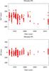 |
Fig. 5 Distribution of the offsets for Miranda as a function of time. |
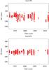 |
Fig. 6 Distribution of the offsets for Ariel as a function of time. |
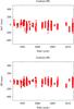 |
Fig. 7 Distribution of the offsets for Umbriel as a function of time. |
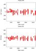 |
Fig. 8 Distribution of the offsets for Titania as a function of time. |
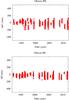 |
Fig. 9 Distribution of the offsets for Oberon as a function of time. |
The standard deviations, as shown in Cols. 4 and 5 in Tables 3 to 7, peak in right ascension. Although it is not easy to clearly identify the reason for this feature, some hypothesis may be investigated.
Known small mechanical problems that affect the telescope tracking system might be responsible for a degradation in the quality of the measurements in right ascension. However, in this case, standard deviations in right ascension should be systematically larger than those in declination, and this is not verified.
Another source of larger uncertainties are occurrences of incorrect timing inserted in the image headers. This mostly affects the right ascension measurements and is known to have happened in the past (before 2000). Figure 10 illustrates this point. We note that both mechanical and timing problems may slightly increase or decrease the values in right ascension in our case. We therefore expect on average larger standard deviations and not a systematic effect.
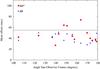 |
Fig. 10 Offsets in right ascension (squares) and declination (triangles) as a function of the angle Sun-observer-Oberon. Each symbol is the average of 200 offsets. The horizontal line was set at ordinate 55 mas. Only data from Oberon were used here. |
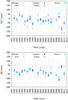 |
Fig. 11 Offsets in right ascension (upper panel) and declination (lower panel), as given by Tables 3 to 7, to all five satellites. Note that the offsets in right ascension for Miranda, measured in 2004 and 2006, fall outside the limits of the y-axis. |
The only points above the threshold of 55 mas in Fig. 10 are those in right ascension and not far from opposition, where the movement of Uranus (most of it along right ascension) is faster. The value of 55 mas is arbitrary to some extent and was chosen because the standard deviations in declination (Col. 5 in Tables 3 to 7) are almost all smaller than it. Therefore, some timing problem is a plausible and probable explanation. Figure 10 also shows a number of observations far from opposition that are therefore helpful for determining the heliocentric distance of Uranus and its satellites.
Another interesting point about the offsets is shown in Fig. 11 where it is possible to note that, except for Miranda, the yearly offsets in right ascension and declination are similiar. The overall offsets for all five satellites are shown in Table 8. This is an indication that the offsets we find are mostly due to the planetary ephemeris DE432, that is, due to the ephemeris position of the barycenter of the Uranus system. Support for this result is also obtained from Cols. 2 and 3 in Table 9.
At this point, it is interesting to check whether our observed positions might also be an improvement to models of the satellite motions. A simple way of checking this is given by Figs. 12 to 16. In them, each symbol is the mean of 100 offsets, and the length of the error bars, above and below the respective dots or triangles, is three times the error of the mean.
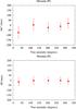 |
Fig. 12 Distribution of the offsets for Miranda as a function of the true anomaly. Solid dots: orbit view close to face-on. Note that there were not enough positions of Miranda with an orbit view close to the edge-on to appear in these plots. |
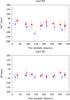 |
Fig. 13 Distribution of the offsets for Ariel as a function of the true anomaly. Solid dots: orbit view close to face-on. Solid triangles: orbit view close to edge-on. |
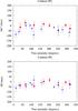 |
Fig. 14 Distribution of the offsets for Umbriel as a function of the true anomaly. Solid dots: orbit view close to face-on. Solid triangles: orbit view close to edge-on. |
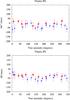 |
Fig. 15 Distribution of the offsets for Titania as a function of the true anomaly. Solid dots: orbit view close to face-on. Solid triangles: orbit view close to edge-on. |
It is possible to note systematic deviations in the offsets of both right ascension and declination as a function of the true anomaly. Positions from observations made with the satellite orbits close to edge-on tend to be more affected by systematic effects than those from observations made with the satellite orbits close to face-on. However, both sets of positions present systematic effects, and a theory that corrects for them would mean an improvement to the dynamical models for the motions of these satellites.
5. Comparisons with other ephemerides
We also compared our positions with those obtained from the recent planetary ephemeris INPOP13c (Fienga et al. 2014) and from the dynamical model for the motion of the five main satellites of Uranus NOE-7-20137. This model is a more recent adjustment of the motions of the satellites than that given by Lainey (2008).
In this section, only observed positions of Oberon are used for the comparisons.
Overall offsets, all satellites.
Overall residuals with respect to Oberon.
5.1. INPOP13c
Table 10 lists the yearly offsets in the sense observed minus ephemeris (INPOP13c+ura111) positions. We note that the right ascension between INPOP13c and our observations agrees better than in DE432. However, the opposite is observed for the offsets in declination. The very last line of Table 10 shows information that is equivalent to that in Table 8 for Oberon, according to INPOP13c+ura111, and can be assumed as a proxy to the offsets of the other satellites.
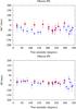 |
Fig. 16 Distribution of the offsets for Oberon as a function of the true anomaly. Solid dots: orbit view close to face-on. Solid triangles: orbit view close to edge-on. |
5.2. NOE-7-2013
Table 11 gives the yearly offsets in the sense observed minus ephemeris (DE432+NOE-7-2-13) positions. The results are similar to those given in Table 7. This is expected since, as mentioned earlier in the text, the main source of differences between observed and ephemeris positions is the planetary ephemerides, which are responsible for the description of the motion of the barycenter of the Uranus system around the barycenter of the solar system.
When we compare the offsets presented in Tables 10 and 7 with those presented in Tables 11 and 7, we note that the planetary ephemerides clearly agree less well between each other than the models for the satellite motions (at least for the bodies studied here).
6. Previous data from the Pico dos Dias Observatory for the main satellites of Uranus
Raw images of the Uranus system, made at the Pico dos Dias observatory before 1992, are no longer available so that V03 was the natural choice to provide an extension of this work to previous epochs.
Our aim here is not to change the values of the positions given by V03. Instead, we simply applied two of the filters described in Sect. 4 to somewhat homogenise their positions8 and ours. Procedures equivalent to the other filters were taken into consideration by these authors when preparing their data. We also provide a brief analysis of the respective filtered positions.
In this context, we applied the filter based on the distance from the centre of Uranus (Perkin-Elmer telescope) and then the filter based on the relative positions of Oberon with respect to those of the other satellites.
For a first verification, however, the data reported in V03 were separated into two sets: photographic (1988 and older) and CCD (after 1988) observations. The results are presented in the same way as for Table 9 in Table 12. The filter related to the distance from the centre of Uranus only eliminated Miranda data (62 positions) because the satellites were observed when their orbits were mostly face-on.
Results for Oberon with INPOP13c+ura111.
Results for Oberon with DE432+NOE-7-2013.
Overall residuals with respect to Oberon from V03.
It is expected, in Table 12, that the standard deviations for the photographic measurements be larger than those made with CCD. In addition, since this work profited from a better reference catalogue for astrometry, we consider that the efforts of V03 to determine relative angular measurements for the satellites were efficient, although the standard deviations in Table 12 are larger than those in Table 9.
In this context, we consider that both photographic and CCD positions are a homogeneous set of data, despite the much larger uncertainties of the Miranda photographic positions. From this point on, we therefore emphasise that the filter based on the relative positions of Oberon with respect to those of the other satellites is applied without distinguishing between the detectors for the V03 data. This slightly changes the total number (CCD plus photographic) of positions for each satellite as given by the last column of Table 12.
Comparison between the positions reported by V03 and those from this work.
Table 13 compares the original, filtered positions from V03, with those obtained in this work. We note that V03 is closer to our results than to those of the ephemerides they used for comparison (DE403 and GUST86).
It is worth mentioning that V03 used the USNO-A2.0 (Monet 1998) catalogue as reference for astrometry and applied corrections on it to minimise systematic effects on its positions. It is known from Assafin et al. (2001) that these effects are larger (in absolute value) than the offsets between V03 and this work (see Table 13). Therefore, the correction that V03 applied on the USNO-A2.0, as expected, brought the celestial frame originally represented by that catalogue closer to that represented by the UCAC4. Most probably, smaller offsets and standard deviations would have been seen in Table 13 (V03 minus this work section) if proper motions were available to all reference stars used by V03. These authors reported geocentric positions and we changed our positions accordingly for these comparisons.
Figures 17 to 21 show the differences in the sense V03 minus this work as a function of time. The dimensions of the axes in these figures facilitate the comparison with the similar axes in V03.
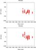 |
Fig. 17 Updated offsets of V03 for Miranda as a function of time. |
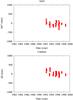 |
Fig. 18 Updated offsets of V03 for Ariel as a function of time. |
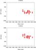 |
Fig. 19 Updated offsets of V03 for Umbriel as a function of time. |
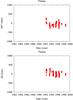 |
Fig. 20 Updated offsets of V03 for Titania as a function of time. |
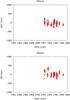 |
Fig. 21 Updated offsets of V03 for Oberon as a function of time. |
7. Position catalogues: Uranus and its main satellites
Catalogues containing all the observed positions of the five main satellites and Uranus, as well as the X and Y CCD coordinates of the observed satellites and reference stars, are only available at the Centre de Données astronomiques de Strasbourg (CDS). Table 14 shows an extract of one such catalogue of positions for Oberon. Positions of Uranus (see Table 15 for an extract) are also provided. Total counts are provided in Table 16.
Positions of Oberon (extract).
Since Uranus is saturated in most of the images, its positions (see Table 15) were not measured. They were derived by applying the mean offset on the ephemeris position of Uranus as obtained from the satellites in the same image (except for Miranda). We stress that the positions of Uranus provided in this paper are not observed ones.
We also note that ephemeris positions of Uranus and the offsets for the satellites are both determined from DE432+ura111 (this is also valid when we determine positions of Uranus from V03 data). Taking into consideration that the positions in Table 15 were most frequently derived from the offsets of two to four satellites, discrepancies in ura111 (for instance, Figs. 12 to 16) are attenuated and, therefore, the derived positions of Uranus can be regarded as ephemeris independent.
Positions from V03 from before 1992 for Uranus and the main satellites are provided in separate catalogues (and separately from our data) with the same format as shown in Tables 14 and 15, respectively. They are filtered by the procedure described in Sect. 6 and presented in their original form, that is, the right ascensions and declinations are exactly those provided by their paper. The application of the offsets given by the lower part of Table 13 on V03 positions is a way to improve their results. We also note that two extra columns are provided in the tables, containing the data from V03. They give the values Δαcosδ and Δδ, in units of milliarcseconds, that should be added to the right ascension and declination, respectively, to transfer these positions from the geocenter to the topocenter.
The observational data in V03 span from 1982 to 1998, so that all positions we provide after 1998 (5827 for the five satellites) are certainly unprecedented.
We stress that our positions are topocentric, whereas the original positions of V03 are geocentric.
Positions of Uranus (extract).
Total counts for the catalogues.
7.1. Uncertainties in position
Uncertainties in position (see Tables 14 and 15) are given by 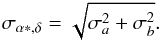 (1)For all satellites whose positions were determined in this work, σa is the standard deviation in right ascension or declination of the reference stars in the image containing the respective satellite and σb is read from Cols. 4 (right ascension) or 5 (declination) in Table 9 for the corresponding satellite. For Oberon, the values of 32 mas (right ascension) or 29 mas (declination) were used for σb. They represent the mean values of the uncertainties in Table 9 for Ariel, Umbriel, and Titania. For satellite positions from V03, uncertainties were determined by taking σa = 100 mas (right ascension and declination), and σb is read from Cols. 4 (right ascension) or 5 (declination) in Table 12 for the corresponding satellite. For Oberon, the values of 43 mas (right ascension) and 51 mas (declination) were used for σb. They represent the mean values of the uncertainties in Table 12 (CCD section, where most of the positions are found) for Ariel, Umbriel, and Titania. The value of 100 mas for σa is a tentative agreement between Cols. 4 and 5 in Table 13 (V03 minus this work section), in an attempt to reproduce the standard deviation of the reference stars in V03.
For all positions of Uranus determined in this work, σa is the standard deviation of the reference stars in right ascension or declination in the respective image containing Uranus, and σb is the standard deviation of the satellite offsets in either right ascension or declination, used to correct the ephemeris position of Uranus. When only one satellite was used, 32 mas (right ascension) or 29 mas (declination) were used for σb, see the reasoning given above for these values. For positions of Uranus from V03, uncertainties were determined by taking again σa = 100 mas (right ascension and declination) and σb as the standard deviation of the offsets of the satellites, in either right ascension or declination, used to correct the ephemeris position of Uranus. When only one satellite was used, the values of 43 mas (right ascension) or 51 mas (declination) were taken, see the reasoning given above for these values.
8. Conclusions and comments
We determined accurate positions of the five main satellites of Uranus: Miranda, Ariel, Umbriel, Titania, and Oberon for the time span 1992–2011 from observations made at the Pico dos Dias Observatory. Positions of Uranus, derived from those of the satellites, were also determined. The standard deviation of the offsets is typically between 40 mas and 65 mas.
Our positions contribute to the general knowledge of the physics of the Uranus system (see Jacobson 2014) to improve modern planetary ephemerides, such as DE432 and INPOP13c, as well as modern models of the satellite motions, such as ura111 and NOE-7-2013.
A number of observations made far from the opposition are certainly useful to improve the determination of the heliocentric distance of Uranus.
The positions from V03 can be used to provide an extension to previous epochs of our data. The application of the offsets provided by the lower section of Table 13 on their original positions is a way to improve them.
http://www.lna.br/, page in Portuguese.
The digital coronography procedure is also part of this package.
Generated by the Uranus Viewer Tool, PDS Rings Node, http://pds-rings.seti.org/
Available at http://www.imcce.fr/hosted_sites/saimirror/burpomaf.htm
Acknowledgments
J.I.B. Camargo acknowledges CNPq for a PQ2 fellowship (process number 308489/2013-6). F.P. Magalhães acknowledges a CAPES fellowship (process number 657943) for a MSc. at Observatório Nacional. R.V.M. acknowledges grants CNPq-306885/2013, Capes/Cofecub-2506/2015, and Faperj/PAPDRJ-45/2013. M.A. acknowledges CNPq grants 473002/2013-2, 482080/2009-4 and 308721/2011-0, and FAPERJ grant 111.488/2013. F.B.R. acknowledges PAPDRJ-FAPERJ/CAPES E-43/2013 number 144997, E-26/101.375/2014. ARGJ thanks for the financial support of CAPES. Software routines from the IAU SOFA Collection were used. Copyright © International Astronomical Union Standards of Fundamental Astronomy (http://www.iausofa.org). NOE-7-2013-MAIN ephemeris and data are issued from the activity of the Bureau des Longitudes in Celestial Mechanics and Astrometry. It was supported by the ESPaCE (European Satellite Partnership for Computing Ephemerides) FP7-Program under ESA grant agreement contract 263466. All softwares we used from SOFA, SPICE, and NOVAS are in FORTRAN.
References
- Acton, C. H. 1996, Planet. Space Sci., 44, 65 [NASA ADS] [CrossRef] [Google Scholar]
- Arias, E. F., Charlot, P., Feissel, M., & Lestrade, J. 1995, A&A, 303, 604 [NASA ADS] [Google Scholar]
- Arlot, J.-E. 2008, in IAU Symp., 248, eds. W. J. Jin, I. Platais, & M. A. C. Perryman, 66 [Google Scholar]
- Assafin, M., Andrei, A. H., Martins, R. V., et al. 2001, ApJ, 552, 380 [NASA ADS] [CrossRef] [Google Scholar]
- Assafin, M., Campos, R. P., Vieira Martins, R., et al. 2008, Planet. Space Sci., 56, 1882 [NASA ADS] [CrossRef] [Google Scholar]
- Assafin, M., Vieira-Martins, R., Braga-Ribas, F., et al. 2009, AJ, 137, 4046 [NASA ADS] [CrossRef] [EDP Sciences] [Google Scholar]
- Assafin, M., Camargo, J. I. B., Vieira Martins, R., et al. 2010, A&A, 515, A32 [NASA ADS] [CrossRef] [EDP Sciences] [Google Scholar]
- Assafin, M., Vieira Martins, R., Camargo, J. I. B., et al. 2011, in Gaia follow-up network for the solar system objects: Gaia FUN-SSO workshop proceedings, held at IMCCE – Paris Observatory, France, November 29 – December 1, 2010, eds. P. Tanga, & W. Thuillot, 85 [Google Scholar]
- Benedetti-Rossi, G., Vieira Martins, R., Camargo, J. I. B., Assafin, M., & Braga-Ribas, F. 2014, A&A, 570, A86 [NASA ADS] [CrossRef] [EDP Sciences] [Google Scholar]
- Braga-Ribas, F., Sicardy, B., Ortiz, J. L., et al. 2014, Nature, 508, 72 [NASA ADS] [CrossRef] [Google Scholar]
- Desmars, J., Camargo, J. I. B., Braga-Ribas, F., et al. 2015, A&A, submitted [Google Scholar]
- Emelyanov, N. V., & Nikonchuk, D. V. 2013, MNRAS, 436, 3668 [NASA ADS] [CrossRef] [Google Scholar]
- Fienga, A., Manche, H.„ Laskar, J. Gantineau, M., & Verma, A. 2014, Arxiv e-prints [arXiv:1405.0484] [Google Scholar]
- Folkner, W. M., Williams, J. G., Boggs, D. H., Park, R. S., & Kuchynka, P. 2014, Interplanetary Network Progress Report, 196, C1 [Google Scholar]
- Hidas, M. G., Christou, A. A., & Brown, T. M. 2008, MNRAS, 384, L38 [NASA ADS] [CrossRef] [Google Scholar]
- Jacobson, R. A. 2014, AJ, 148, 76 [NASA ADS] [CrossRef] [Google Scholar]
- Lainey, V. 2008, Planet. Space Sci., 56, 1766 [Google Scholar]
- Lainey, V., Arlot, J.-E., Karatekin, Ö., & van Hoolst, T. 2009, Nature, 459, 957 [NASA ADS] [CrossRef] [PubMed] [Google Scholar]
- Monet, D. 1998, USNO-A2.0 (US Naval Observatory) [Google Scholar]
- Nogueira, E., Brasser, R., & Gomes, R. 2011, Icarus, 214, 113 [NASA ADS] [CrossRef] [Google Scholar]
- Person, M. J., Elliot, J. L., Gulbis, A. A. S., et al. 2006, AJ, 132, 1575 [NASA ADS] [CrossRef] [Google Scholar]
- Sicardy, B., Bellucci, A., Gendron, E., et al. 2006, Nature, 439, 52 [NASA ADS] [CrossRef] [PubMed] [Google Scholar]
- Tody, D. 1993, in Astronomical Data Analysis Software and Systems II, eds. R. J. Hanisch, R. J. V. Brissenden, & J. Barnes, ASP Conf. Ser., 52, 173 [Google Scholar]
- Veiga, C. H., Vieira Martins, R., & Andrei, A. H. 2003, AJ, 125, 2714 [NASA ADS] [CrossRef] [Google Scholar]
- Widemann, T., Sicardy, B., Dusser, R., et al. 2009, Icarus, 199, 458 [NASA ADS] [CrossRef] [Google Scholar]
- Zacharias, N., Finch, C. T., Girard, T. M., et al. 2013, AJ, 145, 44 [NASA ADS] [CrossRef] [EDP Sciences] [Google Scholar]
All Tables
All Figures
|
Fig. 1 Image containing Uranus and its main satellites, as obtained on 18 July, 1992, with the Perkin-Elmer telescope. Upper left (right) panel: inverted colour map image before (after) the application of the digital coronography procedure. Lower left (right) panel: respective Miranda flux profile along a segment placed on the line joining the centres of Uranus and Miranda. This segment is the same in the two lower panels. Image orientation is north up and east left. Exposure time is 9 s. All other objects in the image that do not belong to the system of Uranus are field stars. |
| In the text | |
|
Fig. 2 Distribution of the number of observations per year. |
| In the text | |
|
Fig. 3 Distribution of the number of observations per year after applying filters 1 to 5. |
| In the text | |
|
Fig. 4 Evolution of the pole position of Uranus, with the view6 of the satellite’s orbit planes gradually changing from close to face-on (1992) to edge-on (2007). |
| In the text | |
|
Fig. 5 Distribution of the offsets for Miranda as a function of time. |
| In the text | |
|
Fig. 6 Distribution of the offsets for Ariel as a function of time. |
| In the text | |
|
Fig. 7 Distribution of the offsets for Umbriel as a function of time. |
| In the text | |
|
Fig. 8 Distribution of the offsets for Titania as a function of time. |
| In the text | |
|
Fig. 9 Distribution of the offsets for Oberon as a function of time. |
| In the text | |
|
Fig. 10 Offsets in right ascension (squares) and declination (triangles) as a function of the angle Sun-observer-Oberon. Each symbol is the average of 200 offsets. The horizontal line was set at ordinate 55 mas. Only data from Oberon were used here. |
| In the text | |
|
Fig. 11 Offsets in right ascension (upper panel) and declination (lower panel), as given by Tables 3 to 7, to all five satellites. Note that the offsets in right ascension for Miranda, measured in 2004 and 2006, fall outside the limits of the y-axis. |
| In the text | |
|
Fig. 12 Distribution of the offsets for Miranda as a function of the true anomaly. Solid dots: orbit view close to face-on. Note that there were not enough positions of Miranda with an orbit view close to the edge-on to appear in these plots. |
| In the text | |
|
Fig. 13 Distribution of the offsets for Ariel as a function of the true anomaly. Solid dots: orbit view close to face-on. Solid triangles: orbit view close to edge-on. |
| In the text | |
|
Fig. 14 Distribution of the offsets for Umbriel as a function of the true anomaly. Solid dots: orbit view close to face-on. Solid triangles: orbit view close to edge-on. |
| In the text | |
|
Fig. 15 Distribution of the offsets for Titania as a function of the true anomaly. Solid dots: orbit view close to face-on. Solid triangles: orbit view close to edge-on. |
| In the text | |
|
Fig. 16 Distribution of the offsets for Oberon as a function of the true anomaly. Solid dots: orbit view close to face-on. Solid triangles: orbit view close to edge-on. |
| In the text | |
|
Fig. 17 Updated offsets of V03 for Miranda as a function of time. |
| In the text | |
|
Fig. 18 Updated offsets of V03 for Ariel as a function of time. |
| In the text | |
|
Fig. 19 Updated offsets of V03 for Umbriel as a function of time. |
| In the text | |
|
Fig. 20 Updated offsets of V03 for Titania as a function of time. |
| In the text | |
|
Fig. 21 Updated offsets of V03 for Oberon as a function of time. |
| In the text | |
Current usage metrics show cumulative count of Article Views (full-text article views including HTML views, PDF and ePub downloads, according to the available data) and Abstracts Views on Vision4Press platform.
Data correspond to usage on the plateform after 2015. The current usage metrics is available 48-96 hours after online publication and is updated daily on week days.
Initial download of the metrics may take a while.