| Issue |
A&A
Volume 551, March 2013
|
|
|---|---|---|
| Article Number | L7 | |
| Number of page(s) | 5 | |
| Section | Letters | |
| DOI | https://doi.org/10.1051/0004-6361/201220771 | |
| Published online | 19 February 2013 | |
Improved CLEAN reconstructions for rotation measure synthesis with maximum likelihood estimation ⋆
1
Max Planck Institute for Astrophysics,
Karl-Schwarzschild-Str. 1,
85748
Garching,
Germany
e-mail:
This email address is being protected from spambots. You need JavaScript enabled to view it.
2
Jacobs University, Campus Ring 1, 28759
Bremen,
Germany
Received:
21
November
2012
Accepted:
21
January
2013
Abstract
The CLEAN deconvolution algorithm has well-known limitations due to the restriction of locating point source model components on a discretized grid. In this Letter, we demonstrate that these limitations are even more pronounced when applying CLEAN in the case of rotation measure (RM) synthesis imaging (known as RMCLEAN in this context). We suggest an approach that uses maximum likelihood estimation to adjust the RMCLEAN-derived model. We demonstrate through the use of mock, one-dimensional RM synthesis observations that this technique improves significantly over standard RMCLEAN and gives results that are independent of the chosen pixelization. We suggest using this simple modification to RMCLEAN in upcoming polarization sensitive sky surveys.
Key words: polarization / methods: data analysis / techniques: polarimetric / techniques: image processing
Appendix A is available in electronic form at http://www.aanda.org
© ESO, 2013
1. Introduction
CLEAN (Högbom 1974) is a deconvolution algorithm that is widely used throughout astronomy. Using CLEAN, a deconvolved image is constructed iteratively by locating the maximum in the image, adding a delta function at that location with some fraction of the peak brightness to a model, and then subtracting the point spread function (PSF) that has been shifted to the location of the model component and scaled by its strength. This is repeated until a user-defined stop condition has been reached. The model is then convolved with an idealized PSF and added back to the residual data.
The algorithm makes an implicit assumption that the image is well described by a collection of statistically independent point sources. In some cases this is justified and experience has shown that even when this assumption is not ideal, CLEAN is still able to produce qualitatively reasonable results.
Using CLEAN, the model point sources are constrained to be located on a regularly spaced grid due to the discretization of the image space. To properly remove the PSF pattern associated with a strong point source, it is crucial for the delta function representing the source in the CLEAN model to have an accurate position. While the PSF limits the minimum spatial scale of structures that can be resolved, the accuracy with which one can measure the location of a point source depends on the signal-to-noise ratio. In the high signal-to-noise regime the uncertainty in the location of a source can be much smaller than the PSF, and to measure the source location accurately with a single model point source one would have to create an image with a large number of pixels within the PSF. Such oversampling is at best computationally wasteful and in some cases may make the imaging problem computationally unfeasible. For example, even with a few pixels per resolution element, three-dimensional (3D) Faraday synthesis (Bell & Enßlin 2012) images will easily exceed the available memory on a single computer for typical upcoming polarization surveys with e.g. the Australian Square Kilometer Array Pathfinder (ASKAP, Johnston et al. 2008) and the LOw-Frequency ARray (LOFAR, van Haarlem et al., in prep.).
CLEAN is able to partially overcome this issue by describing a single point source using a cluster of CLEAN components around the true source location. The strongest model source will lie on the pixel closest to the source location. Weaker model points will be added to neighboring grid points such that when the collection of model sources is convolved with the idealized PSF, the resulting image will be closer to the true source position and flux than that of a single model point located on the grid. Nevertheless, inaccuracies in image reconstructions due to the pixelization of the sky are a well known limiting factor to dynamic range when using CLEAN (Briggs & Cornwell 1992; Perley 1999; Cotton & Uson 2008; Yatawatta 2010).
Rotation measure (RM) synthesis (Brentjens & de
Bruyn 2005) is a promising new technique for studying magnetic fields with the new
generation of broadband radio telescopes. RM synthesis allows for the separation of multiple
sources of polarized emission along a line of sight when each is Faraday rotated by
different amounts. It produces an estimate of the Faraday spectrum, or the polarized
emission as a function of the Faraday depth. The Faraday depth, φ, which is
a quantity that measures the amount of Faraday rotation, is proportional to
 where
ne is the density of thermal electrons and
Bz is the component of the magnetic field
along the line of sight. CLEAN has been proposed as a deconvolution technique to be applied
to RM synthesis (Heald et al. 2009), and is often
referred to as RMCLEAN in this context. Several alternative reconstruction techniques have
been proposed (Frick et al. 2010; Li et al. 2011; Andrecut
et al. 2012), but RMCLEAN has thus far been used most often as the deconvolution
method of choice (Feain et al. 2009; Harvey-Smith et al. 2010; Mao et al. 2010; Bernardi et al. 2010; Brentjens 2011; Van Eck et
al. 2011; Heald 2012; Mao et al. 2012a,b; van Weeren et al. 2012; Iacobelli et al. 2013).
where
ne is the density of thermal electrons and
Bz is the component of the magnetic field
along the line of sight. CLEAN has been proposed as a deconvolution technique to be applied
to RM synthesis (Heald et al. 2009), and is often
referred to as RMCLEAN in this context. Several alternative reconstruction techniques have
been proposed (Frick et al. 2010; Li et al. 2011; Andrecut
et al. 2012), but RMCLEAN has thus far been used most often as the deconvolution
method of choice (Feain et al. 2009; Harvey-Smith et al. 2010; Mao et al. 2010; Bernardi et al. 2010; Brentjens 2011; Van Eck et
al. 2011; Heald 2012; Mao et al. 2012a,b; van Weeren et al. 2012; Iacobelli et al. 2013).
In this Letter, we show that the limitations of CLEAN due to pixelization of the sky are particularly pronounced in the case of RM synthesis, and propose to use a maximum likelihood (ML) estimation procedure to improve the model obtained using the standard RMCLEAN algorithm. This method is similar to those proposed previously in the context of high-fidelity aperture synthesis imaging (El-Behery & MacPhie 1980; Yatawatta 2010; Bernardi et al. 2011). It is also similar to the method proposed by O’Sullivan et al. (2012), but is more easily scaled to higher dimensions and includes fewer assumptions about the Faraday spectrum. Our aim is to maintain or improve accuracy of the standard RMCLEAN algorithm while keeping the number of pixels to a minimum.
2. The algorithm
With 1D RM synthesis one attempts to reconstruct the complex valued Faraday spectrum, s, from polarized sky brightness data, d, that has been collected at many wavelengths, λ. We note that the following description is trivially extended to 3D as would be required in the case of Faraday synthesis (Bell & Enßlin 2012), which combines aperture and RM synthesis into a single procedure that provides significantly better results than when they are performed separately.
For RM synthesis, the following measurement equation applies: 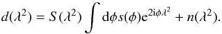 (1)Here, n
is a Gaussian additive noise term and S represents a sampling function
defining the discrete λ2 values at which measurements are
obtained.
(1)Here, n
is a Gaussian additive noise term and S represents a sampling function
defining the discrete λ2 values at which measurements are
obtained.
Using the RMCLEAN algorithm, one generates a list of model points
M = { mi,φi } i
with flux values and positions given by mi and
φi, respectively, where i is
an index over the list of NM model points. The
representation of the model in data space is 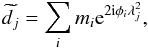 (2)where j is
an index over the Nd values of
λ2 for which measurements have been made. We note that
m, n, d and
(2)where j is
an index over the Nd values of
λ2 for which measurements have been made. We note that
m, n, d and
 are all complex valued.
We assume that the probability of measuring the full data set, d, given
the RMCLEAN model (i.e. the likelihood), is a product of the probabilities of measuring each
individual data point, di. In this way, we
assume the measurements to be independent of one another, thus making the likelihood
 (3)Here, as mentioned
previously, we assume Gaussian distributed noise, and
(3)Here, as mentioned
previously, we assume Gaussian distributed noise, and
 is the variance
of the noise in channel j. For simplicity, we assume that the noise
variance is equal in both the real and imaginary parts of
.
This may not be true in general, but the generalization to differing noise levels or
correlated noise in Q and U is trivial.
is the variance
of the noise in channel j. For simplicity, we assume that the noise
variance is equal in both the real and imaginary parts of
.
This may not be true in general, but the generalization to differing noise levels or
correlated noise in Q and U is trivial.
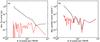 |
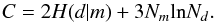
Fig. 1 Comparison of the a) flux and b) position errors as a function of pixel size in reconstructions of a single point source using RMCLEAN (black line) and the ML algorithm described in this paper (red line). The reported errors are the average absolute errors from 100 simulated data sets. |
Our approach is to adjust the CLEAN model by maximizing the likelihood with respect to
mi and
φi. For simplicity, we opt to work with the
negative log-likelihood ![Mathematical equation: \begin{equation} H(d|M)=-\textrm{ln}\, P(d|M)=\frac{1}{2}\sum_{j}\left[\frac{\left(d_{j}-\widetilde{d_{j}}\right)^{2}}{\sigma_{j}^{2}}+\textrm{ln}\left(2\pi\sigma_{j}^{2}\right)\right].\label{eq:log_likelihood} \end{equation}](/articles/aa/full_html/2013/03/aa20771-12/aa20771-12-eq27.png) (4)The ML solution is obtained
by minimizing this function. There are many possible approaches to minimizing Eq. (4). The iterative procedure that we use is
presented in Appendix A.
(4)The ML solution is obtained
by minimizing this function. There are many possible approaches to minimizing Eq. (4). The iterative procedure that we use is
presented in Appendix A.
Minimization of Eq. (4) provides an estimate for the optimal model parameters under the assumption that the number of point sources in the initial RMCLEAN model is appropriate. This, however, is almost certainly not the case. RMCLEAN will naturally over-estimate the number of point sources that are required to model the data because it needs a cluster of sources in order to model a single source at an arbitrary location.
To find the most appropriate number of free parameters in the model that are supported by
the data, we modify H to add a term that penalizes additional degrees of
freedom. We use the so-called Bayesian information criterion (BIC, Schwarz 1978) to suit this role. The BIC, C, is given by
 (5)The algorithm
proceeds as follows:
(5)The algorithm
proceeds as follows:
-
1.
Start with a list of model point sources generated byRMCLEAN. Condense the model such that there is only one entryper pixel location.
-
2.
Throw away any model entries where |mi| is below a user-defined threshold, thus, removing model points that result from cleaning too deeply or that only function to slightly shift a single point source location. We use a threshold of twice the noise level in the Faraday spectrum. This step is not necessary, but can speed up computation in case there are many excess point sources in the initial model.
-
3.
Take one or more steps to iteratively minimize Eq. (4) for the current model using e.g. the prescription outlined in Appendix A.
-
4.
Attempt to merge nearby model points. Pairwise combine RMCLEAN components into a single component having a location at the flux-weighted mean location and a flux that is either the sum of the two model point fluxes or that is solved for using e.g. Eq. (A.7). Accept the merged RMCLEAN component if C is reduced, otherwise revert to the previous model.
-
5.
Iterate steps 3 and 4 until the fractional change in H from one step to the next is below a user-defined threshold. In our tests we use 10-5 as a stop criterion.
-
6.
Obtain a residual Faraday spectrum by subtracting the new model from the data.
-
7.
Convolve the new model with an idealized PSF and add it to the residual spectrum.
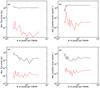 |
Fig. 2 As Fig. 1 but with the average errors of two sources that are separated by 2 × FWHM (top row) and 6 × FWHM (bottom row). |
3. Demonstration
To demonstrate the effectiveness of the approach outlined above, we present a series of 1D RM synthesis mock observations of simple single and double point-source sky models. We generate simulated data according to Eq. (1) including Gaussian random white noise and sample using a frequency coverage with 800 channels equally spaced between 1 and 4.2 GHz. This frequency range is similar to that of the combination of the upgraded Very Large Array L- and S-band receivers and corresponds to a PSF with a full width at half maximum (FWHM) of the main peak of ~40 rad/m2. A Clark-style RMCLEAN (Clark 1980) is then performed (i.e. the model is subtracted in λ2-space rather than in φ-space) and the resulting model is used as input for the ML algorithm. The output spectra from both procedures are stored for comparison.
In Fig. 1, we compare the results from standard RMCLEAN to those of the ML method when reconstructing the position and flux of a single point source as a function of pixel size. The source is located at roughly the same φ location at each resolution, but shifted slightly to ensure that it is always located one-third of the way between two pixels. The source flux is roughly 100 times the noise level in the spectrum. The plotted flux and position errors are the average of the magnitude of those from 100 trials with different noise realizations. Source position and flux are measured by locating the maximum of the modulus of the Faraday spectrum and fitting a Gaussian to the spectrum around this point. We find that for RMCLEAN the position and flux errors increase significantly with pixel size while those for the ML approach remain nearly constant. Six or more pixels per FWHM of the PSF are required before the positional accuracy for RMCLEAN matches that of the ML approach. To obtain accurate fluxes with RMCLEAN, 40 or more pixels per FWHM are required.
For a sky model with a single source, RMCLEAN is found to work well as long as the spectrum is sufficiently oversampled. With more than one source, however, oversampling is no longer effective, as shown in Fig. 2. Here we show positional and flux errors in the case where there are two sources along the line of sight. In one case, they are separated by 80 rad/m2 (roughly 2 × FWHM of the PSF) and in the other by 240 rad/m2 (6 × FWHM). The modulus and phase of the complex valued flux is the same for both sources. The errors that are plotted are the average of those from both sources (the errors for the individual sources were qualitatively similar). We find that increasing the resolution does not reduce errors in the RMCLEAN reconstruction and that on average these errors are two or more orders of magnitude larger than in the ML reconstructions. This behavior is due to the interactions between the highly structured, complex valued PSFs associated with each point source. The exact dependence on the error as a function of source separation depends on the specific sampling function, and therefore PSF, being used.
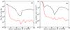 |
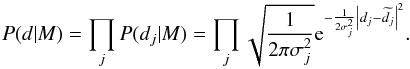
Fig. 3 As Fig. 2 but with fixed resolution and varying source separation, which is given as a multiple of the FWHM of the PSF (40 rad/m2). |
We also find that the errors are larger for both approaches when sources are close together relative to the FWHM of the PSF. To test this further, we kept the resolution fixed (at 5 rad/m2 per pixel) and varied the separation between the two sources (again, each having the same flux and phase). In Fig. 3, we see that below a source separation of 2 × FWHM the errors for both methods increase dramatically. Nevertheless, at separations of 1 × FWHM or larger, the ML approach fares significantly better than RMCLEAN.
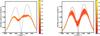 |
Fig. 4 Modulus of the Faraday spectra of two point sources having similar fluxes and the same phase and that are separated by 1 × FWHM (40 rad/m2). The dashed line shows the sky model after convolution with the idealized PSF. The a) RMCLEAN and b) ML reconstructions from 500 trials are plotted in red/yellow. The color scale indicates the log of the number of reconstructions that pass through each location on the figure. |
Even though the errors increase dramatically as source separation decreases for both methods, we find that the ML reconstructions are still better than those from RMCLEAN. In Fig. 4, we show reconstructed Faraday spectra from 500 data realizations of the same sky model. Although the ML results show a systematic reduction in flux and a shift in position relative to the sky model, two distinct sources are clearly identifiable. This is not the case in the RMCLEAN image. We performed similar tests for hundreds of combinations of source separation (between 1 and 6 × FWHM), relative fluxes (flux ratios between 1 and 10), relative phases, and noise levels. In all cases the ML approach performed better than RMCLEAN, and it only showed significant errors and an increased scatter in the results in a few cases like the one shown in Fig. 4.
4. Conclusions
We have shown that the well-known limitations of the CLEAN algorithm that arise due to discretization of the sky are particularly pronounced in the case of RM synthesis. We find that the accuracy of RMCLEAN results depend strongly on the choice of pixelization, and significant oversampling is required to obtain accurate measurements of flux and Faraday depth in the simplest case where there is a single source along the line of sight. Furthermore, RMCLEAN is unable to accurately reconstruct fluxes and locations of individual sources when there are multiple sources of emission, even when oversampling.
We propose an algorithm to adjust the RMCLEAN model parameters using ML estimation and a prescription for reducing the degrees of freedom in the model to the minimum number that are supported by the data. We show that this algorithm improves upon the results obtained using RMCLEAN alone and provides accurate reconstructions independent of the choice of pixelization of Faraday depth space.
Both algorithms struggle in cases where two point sources are located within 1 × FWHM of the PSF, but this merely reflects the fundamental limitation of the observations to resolve structures on these scales. As such, the ML approach is not able to overcome the problems that occur due to interference by closely-spaced sources of the kind demonstrated by Farnsworth et al. (2011). However, although errors increase as source separation decreases, the ML algorithm still provides improvement over RMCLEAN until source separation reaches 0.5 × FWHM.
The algorithm described herein provides significant improvements over RMCLEAN alone and is easy to append to existing RM synthesis imaging pipelines. Therefore, we recommend its use in upcoming polarization surveys that plan to include RM synthesis imaging.
The ML procedure still assumes that the Faraday spectrum is well described by a set of independent point sources, and will likely not be ideal in case large-scale, diffuse emission is present. A point-source based reconstruction method is nevertheless an important tool to have on hand. It can be used as a method for separating point sources from a diffuse background, which may be better reconstructed using other methods that do not handle point sources well. It may also be the optimal deconvolution method for use with instruments that are not sensitive to scales much larger than the PSF, as is the case with e.g. LOFAR (Beck et al. 2012).
Online material
Appendix A: Iterative maximization approach
We assume that the optimal model point position is shifted by some small distance,
δφi,
relative to the grid point location found using RMCLEAN,

 (A.1)The ML solution is
obtained by minimizing H in Eq. (4) with respect to
δφi, which gives
(A.1)The ML solution is
obtained by minimizing H in Eq. (4) with respect to
δφi, which gives
![Mathematical equation: \appendix \setcounter{section}{1} \begin{equation} \frac{\partial H(d|M)}{\partial\delta \phi_{i}}=\frac{2}{\sigma_{n}^{2}}\sum_{j}\Re\left[{\rm i}\lambda^2_{j}m_{i} \left\{m_i^{*} - \left(d_{j} - \widetilde{\widetilde{d_{j}^{i}}}\right)^{*}{\rm e}^{2 {\rm i}\lambda^2_{j}\phi_{i}} \right\}\right]=0,\label{eq:ML_equation} \end{equation}](/articles/aa/full_html/2013/03/aa20771-12/aa20771-12-eq41.png) (A.2)where
(A.2)where
 is the same as
  ,
Eq. (2), except that the sum is over
k ≠ i. The operator ℜ selects the real part of its
argument. This expression cannot be solved analytically for
δφi, but we can use it
to search for the solutions iteratively. To do so we Taylor expand the exponential term
in Eq. (A.2) to first order, thereby
making H second order in
δφi. This gives
,
Eq. (2), except that the sum is over
k ≠ i. The operator ℜ selects the real part of its
argument. This expression cannot be solved analytically for
δφi, but we can use it
to search for the solutions iteratively. To do so we Taylor expand the exponential term
in Eq. (A.2) to first order, thereby
making H second order in
δφi. This gives
![Mathematical equation: \appendix \setcounter{section}{1} \begin{equation} \frac{\partial H}{\partial\delta \phi_{i}}=\frac{2}{\sigma_{n}^{2}}\sum_{j}\Re\left[\lambda^2_{j}m_{i}{\rm i}\left\{m_{i}^{*} - \left(d_{j} - \widetilde{\widetilde{d_{j}^{i}}}\right)^{*}{\rm e}^{2 {\rm i}\lambda^2_{j}\overline{\phi_{i}}}-2 {\rm i}\lambda^2_{j}\left(\widetilde{\widetilde{d_{j}^{i}}}-d_{j}\right)^{*}{\rm e}^{2 {\rm i}\lambda^2_{j}\overline{\phi_{i}}}\delta \phi_{i}\right\} \right]=0, \end{equation}](/articles/aa/full_html/2013/03/aa20771-12/aa20771-12-eq46.png) (A.3)which we can rewrite in
the form
(A.3)which we can rewrite in
the form  (A.4)where
![Mathematical equation: \appendix \setcounter{section}{1} \begin{eqnarray} A = && \sum_{j}\Re\left[\left\{m_{i}^{*} - \left(d_{j}-\widetilde{\widetilde{d_{j}^{i}}}\right)^{*}{\rm e}^{2 {\rm i}\lambda^2_{j}\overline{\phi_{i}}}\right\} \lambda^2_{j}m_{i}{\rm i}\right],\nonumber \\ B = && \sum_{j}\Re\left[-2 \lambda^4_{j}m_{i}\left(d_{j}-\widetilde{\widetilde{d_{j}^{i}}}\right)^{*}{\rm e}^{2 {\rm i}\lambda^2_{j}\overline{\phi_{i}}}\right]. \end{eqnarray}](/articles/aa/full_html/2013/03/aa20771-12/aa20771-12-eq48.png) (A.5)We
must also solve for an updated flux. We can again extremize Eq. (4), this time with respect to
mi. We find
(A.5)We
must also solve for an updated flux. We can again extremize Eq. (4), this time with respect to
mi. We find
![Mathematical equation: \appendix \setcounter{section}{1} \begin{equation} \frac{\partial H}{\partial m_{i}}=\frac{1}{2\sigma_{n}^{2}}\sum_{j}\left[m_{i}^{*}-\left(d_{j}-\widetilde{\widetilde{d_{j}}}\right)^{*}{\rm e}^{2 {\rm i} \phi_{i}\lambda^2_{j}}\right] \end{equation}](/articles/aa/full_html/2013/03/aa20771-12/aa20771-12-eq49.png) (A.6)and
thus
(A.6)and
thus
![Mathematical equation: \appendix \setcounter{section}{1} \begin{equation} m_{i}=\frac{1}{N_d}\sum_{j=1}^{N_d}\left[\left(d_{j}-\widetilde{\widetilde{d_{j}^{i}}}\right){\rm e}^{-2 {\rm i}\phi_{i}\lambda^2_{j}}\right].\label{eq:delta_m_solutions} \end{equation}](/articles/aa/full_html/2013/03/aa20771-12/aa20771-12-eq50.png) (A.7)In our example
implementation, we solve for δφ and m iteratively
until convergence is achieved. We also attempt to merge nearby model components to
reduce the degrees of freedom in the model according to the prescription described in
Sect. 2.
(A.7)In our example
implementation, we solve for δφ and m iteratively
until convergence is achieved. We also attempt to merge nearby model components to
reduce the degrees of freedom in the model according to the prescription described in
Sect. 2.
We tried other iterative schemes, e.g. solving for position and flux changes by inverting the Hessian matrix of H, but found that the approach given here is the most stable.
Acknowledgments
This research was performed in the framework of the DFG Forschergruppe 1254 Magnetisation of Interstellar and Intergalactic Media: the Prospects of Low-Frequency Radio Observations. We thank Henrik Junklewitz and Marco Selig for many helpful discussions, and the anonymous referee for a careful reading of the manuscript and many helpful comments.
References
- Andrecut, M., Stil, J. M., & Taylor, A. R. 2012, AJ, 143, 33 [NASA ADS] [CrossRef] [Google Scholar]
- Beck, R., Frick, P., Stepanov, R., & Sokoloff, D. 2012, A&A, 543, A113 [NASA ADS] [CrossRef] [EDP Sciences] [Google Scholar]
- Bell, M. R., & Enßlin, T. A. 2012, A&A, 540, A80 [NASA ADS] [CrossRef] [EDP Sciences] [Google Scholar]
- Bernardi, G., de Bruyn, A. G., Harker, G., et al. 2010, A&A, 522, A67 [NASA ADS] [CrossRef] [EDP Sciences] [Google Scholar]
- Bernardi, G., Mitchell, D. A., Ord, S. M., et al. 2011, MNRAS, 413, 411 [NASA ADS] [CrossRef] [Google Scholar]
- Brentjens, M. A. 2011, A&A, 526, A9 [NASA ADS] [CrossRef] [EDP Sciences] [Google Scholar]
- Brentjens, M. A., & de Bruyn, A. G. 2005, A&A, 441, 1217 [NASA ADS] [CrossRef] [EDP Sciences] [Google Scholar]
- Briggs, D. S., & Cornwell, T. J. 1992, in Astronomical Data Analysis Software and Systems I, eds. D. M. Worrall, C. Biemesderfer, & J. Barnes, ASP Conf. Ser., 25, 170 [Google Scholar]
- Clark, B. G. 1980, A&A, 89, 377 [NASA ADS] [Google Scholar]
- Cotton, W. D., & Uson, J. M. 2008, A&A, 490, 455 [NASA ADS] [CrossRef] [EDP Sciences] [Google Scholar]
- El-Behery, I., & MacPhie, R. 1980, IEEE Trans. Antenn. Propag., 28, 234 [NASA ADS] [CrossRef] [Google Scholar]
- Farnsworth, D., Rudnick, L., & Brown, S. 2011, AJ, 141, 191 [NASA ADS] [CrossRef] [Google Scholar]
- Feain, I. J., Ekers, R. D., Murphy, T., et al. 2009, ApJ, 707, 114 [NASA ADS] [CrossRef] [Google Scholar]
- Frick, P., Sokoloff, D., Stepanov, R., & Beck, R. 2010, MNRAS, 401, L24 [NASA ADS] [Google Scholar]
- Harvey-Smith, L., Gaensler, B. M., Kothes, R., et al. 2010, ApJ, 712, 1157 [NASA ADS] [CrossRef] [Google Scholar]
- Heald, G. H. 2012, ApJ, 754, L35 [NASA ADS] [CrossRef] [Google Scholar]
- Heald, G., Braun, R., & Edmonds, R. 2009, A&A, 503, 409 [NASA ADS] [CrossRef] [EDP Sciences] [Google Scholar]
- Högbom, J. A. 1974, A&AS, 15, 417 [NASA ADS] [Google Scholar]
- Iacobelli, M., Haverkorn, M., & Katgert, P. 2013, A&A, 549, A56 [NASA ADS] [CrossRef] [EDP Sciences] [Google Scholar]
- Johnston, S., Taylor, R., Bailes, M., et al. 2008, Exp. Astron., 22, 151 [NASA ADS] [CrossRef] [Google Scholar]
- Li, F., Brown, S., Cornwell, T. J., & de Hoog, F. 2011, A&A, 531, A126 [NASA ADS] [CrossRef] [EDP Sciences] [Google Scholar]
- Mao, S. A., Gaensler, B. M., Haverkorn, M., et al. 2010, ApJ, 714, 1170 [NASA ADS] [CrossRef] [Google Scholar]
- Mao, S. A., McClure-Griffiths, N. M., Gaensler, B. M., et al. 2012a, ApJ, 755, 21 [NASA ADS] [CrossRef] [Google Scholar]
- Mao, S. A., McClure-Griffiths, N. M., Gaensler, B. M., et al. 2012b, ApJ, 759, 25 [NASA ADS] [CrossRef] [Google Scholar]
- O’Sullivan, S. P., Brown, S., Robishaw, T., et al. 2012, MNRAS, 421, 3300 [NASA ADS] [CrossRef] [Google Scholar]
- Perley, R. A. 1999, in Synthesis Imaging in Radio Astronomy II, eds. G. B. Taylor, C. L. Carilli, & R. A. Perley, ASP Conf. Ser., 180, 275 [Google Scholar]
- Schwarz, G. 1978, The Annals of Statistics, 6, 461 [Google Scholar]
- Van Eck, C. L., Brown, J. C., Stil, J. M., et al. 2011, ApJ, 728, 97 [NASA ADS] [CrossRef] [Google Scholar]
- van Weeren, R. J., Röttgering, H. J. A., Intema, H. T., et al. 2012, A&A, 546, A124 [NASA ADS] [CrossRef] [EDP Sciences] [Google Scholar]
- Yatawatta, S. 2010, 6th IEEE Sensor Array and Multichannel Signal Processing Workshop [arXiv:1008.1892] [Google Scholar]
All Figures
|
Fig. 1 Comparison of the a) flux and b) position errors as a function of pixel size in reconstructions of a single point source using RMCLEAN (black line) and the ML algorithm described in this paper (red line). The reported errors are the average absolute errors from 100 simulated data sets. |
| In the text | |
|
Fig. 2 As Fig. 1 but with the average errors of two sources that are separated by 2 × FWHM (top row) and 6 × FWHM (bottom row). |
| In the text | |
|
Fig. 3 As Fig. 2 but with fixed resolution and varying source separation, which is given as a multiple of the FWHM of the PSF (40 rad/m2). |
| In the text | |
|
Fig. 4 Modulus of the Faraday spectra of two point sources having similar fluxes and the same phase and that are separated by 1 × FWHM (40 rad/m2). The dashed line shows the sky model after convolution with the idealized PSF. The a) RMCLEAN and b) ML reconstructions from 500 trials are plotted in red/yellow. The color scale indicates the log of the number of reconstructions that pass through each location on the figure. |
| In the text | |
Current usage metrics show cumulative count of Article Views (full-text article views including HTML views, PDF and ePub downloads, according to the available data) and Abstracts Views on Vision4Press platform.
Data correspond to usage on the plateform after 2015. The current usage metrics is available 48-96 hours after online publication and is updated daily on week days.
Initial download of the metrics may take a while.