Fig. 7
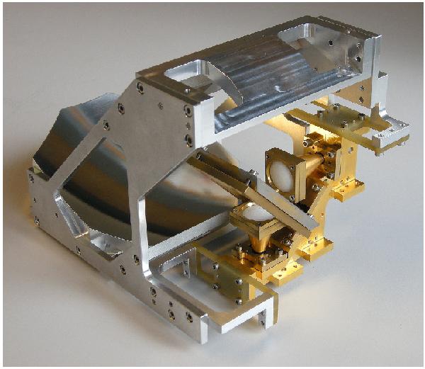
The Band 3 cold optics. In the foreground, the two horns located symmetrically on either side of the polarization diplexing wire grid (seen edge on). Behind each horn sits one local oscillator injection coupler, and between the two couplers, diagonally, the LO power splitter that also serves as a mechanical support for the other elements. That sub-assembly, which is cooled to 4 K, is mechanically linked to, and thermally insulated from the mirror sub-assembly by fiberglass-epoxy (G11) supports.
Current usage metrics show cumulative count of Article Views (full-text article views including HTML views, PDF and ePub downloads, according to the available data) and Abstracts Views on Vision4Press platform.
Data correspond to usage on the plateform after 2015. The current usage metrics is available 48-96 hours after online publication and is updated daily on week days.
Initial download of the metrics may take a while.