


Fig. 10
Download original image
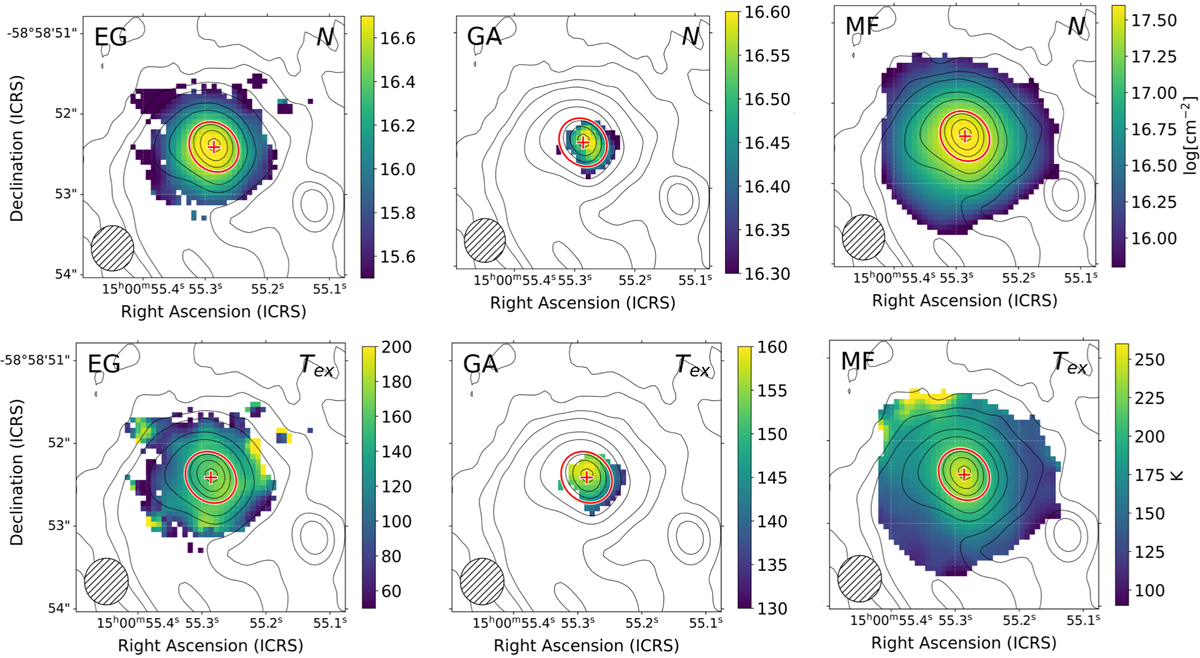
Column density (N) maps (top row) and excitation temperature (Tex) maps (bottom row) derived for EG (left), GA (middle), and MF (right). The corresponding relative errors are shown in Appendix B.1. The black contours correspond to the continuum emission at 5σ, 10σ, 20σ, 30σ, 60σ, 90σ, 180σ, 220σ, and 260σ with σ = 0.28 mJy beam−1, and the red cross shows its peak position. The red ellipses surrounded by white show the location and size of the dust continuum core AG318−c9 as estimated by Coletta et al. (2025). The hatched ellipse shown in the bottom left corner represents the synthesised beam of the interferometer.
Current usage metrics show cumulative count of Article Views (full-text article views including HTML views, PDF and ePub downloads, according to the available data) and Abstracts Views on Vision4Press platform.
Data correspond to usage on the plateform after 2015. The current usage metrics is available 48-96 hours after online publication and is updated daily on week days.
Initial download of the metrics may take a while.