| Issue |
A&A
Volume 684, April 2024
|
|
|---|---|---|
| Article Number | L5 | |
| Number of page(s) | 5 | |
| Section | Letters to the Editor | |
| DOI | https://doi.org/10.1051/0004-6361/202449752 | |
| Published online | 08 April 2024 | |
Letter to the Editor
Differential optical transfer function (dOTF) broad-spectrum wavefront sensing using integral field unit spectroscopy
Université Côte d’Azur, Observatoire de la Côte d’Azur, CNRS, Laboratoire Lagrange, Nice, France
e-mail: This email address is being protected from spambots. You need JavaScript enabled to view it.
Received:
27
February
2024
Accepted:
18
March
2024
Abstract
Context. Detecting and characterizing Earth-like exoplanets is a critical scientific goal for the next generation of telescopes. However, current direct imaging instruments are hindered by evolving noncommon path aberrations (NCPAs), which lead to persistent speckles in the images. The differential optical transfer function (dOTF) is an image-based, noniterative, and model-independent wavefront sensor that combines differential images to estimate the complex field of the pupil.
Aims. Given the objective of spectrally characterizing exoplanets to discern their composition and potentially detect biosignatures, we aim to explore the integration of the dOTF sensing method with an integral field unit (IFU) spectrograph. An IFU spectrograph generates a spectral data cube that contains diverse spectral information within a single dataset. Combining these two concepts is expected to improve the efficiency with which NCPAs can be spectrally measured and characterized.
Methods. This Letter presents an implementation strategy for integrating dOTF and IFU spectroscopy data, enabling estimations of the electric field at various wavelengths simultaneously.
Results. This method is specifically optimized to provide the most effective combination with minimal hardware requirements. It involves the use of multiple simultaneous deformable mirror actuator displacements in conjunction with an adapted Lyot stop employing a circular variable filter.
Conclusions. The dOTF wavefront sensor coupled with an IFU spectrograph promises to be rapid and efficient, capable of measuring NCPAs across the entire spectrum provided by the spectrograph. Because the combination of dOTF and IFU spectroscopy is immediately applicable, it is of potential interest for various present-day on-sky instruments, as well as future IFU-based instruments coupled to the next generation of extremely large telescopes (ELTs).
Key words: instrumentation: high angular resolution / instrumentation: spectrographs / techniques: high angular resolution / techniques: imaging spectroscopy
© The Authors 2024
 Open Access article, published by EDP Sciences, under the terms of the Creative Commons Attribution License (https://creativecommons.org/licenses/by/4.0), which permits unrestricted use, distribution, and reproduction in any medium, provided the original work is properly cited.
This article is published in open access under the Subscribe to Open model. This email address is being protected from spambots. You need JavaScript enabled to view it. to support open access publication.
1. Introduction
In recent years, imaging circumstellar disks and exoplanets has become a popular way to refine models of planetary system formation and to investigate planetary atmospheres. Nonetheless, directly imaging faint sources around bright objects poses significant challenges. The natural sensitivity of a coronagraph to fluctuations in the electric field results in the persistence of residual quasi-static speckles in the image plane. Sustaining nearly aberration-free wavefronts, both in phase and amplitude, is crucial for any coronagraphic instrument. These speckles, which limit the relative brightness and angular separation of an exoplanet to its host star, mostly come from so-called noncommon path aberrations (NCPAs).
The differential optical transfer function (Codona 2012, 2013; Codona & Doble 2015, dOTF) is a phase-retrieval technique used to estimate the complex field of an optical system. The dOTF technique involves the comparison of two images taken in the imaging system’s focal plane, one with a small pupil modification, through their optical transfer function (OTF).
When spectrally characterizing exoplanets to discern their composition and potentially detect biosignatures, integral field unit (IFU, e.g., Beuzit et al. 2019; Crepp et al. 2011; Macintosh et al. 2006; Anagnos et al. 2021; Boccaletti 2021) spectrographs offer the possibility to combine imaging and spectroscopic capabilities in order to acquire spatially resolved 2D spectroscopy in a single exposure. Through dispersing light from distinct spatial elements within the field of view, an image of the source is obtained at each wavelength, simultaneously capturing a spectrum at every spatial position. IFU spectrographs thus provide extremely dense information coverage for a single object at the cost of a relatively small field of view.
Post-processing methods are routinely used on data collected from telescopes to effectively remove residual speckles (e.g., Kuhn et al. 2001; Marois et al. 2005, 2006), even without employing a coronagraph. However, these methods can introduce biases into spectral measurements and become less effective as the angular separation decreases. Focal plane wavefront sensing using an IFU spectrograph has become a subject of research (e.g., Groff et al. 2013). The motivation for the present Letter is to explore the potential of the association between dOTF and IFU spectrograph data, as the spectral data offer a chromatic snapshot with which we can estimate the electric field, which could decrease the residual energy of quasi-static speckles.
2. Differential optical transfer function
The notation ψ is defined as the product of the incident electric field ψ0 and the pupil transmission mask function M. For clarity, pupil plane and focal plane variables are omitted. The Fourier transform of a function f is denoted ℱ(f), and its inverse Fourier transform is expressed as ℱ−1(f). The asterisk represents the complex conjugate, × denotes the product operator, and ⊗ denotes the convolution product. In the dOTF method, the pupil transmission function M can be altered when applying a probe (a pupil modification), as described in Codona (2013), so that M transforms into M + δM. The OTF, represented by 𝒪, is the auto-correlation of the pupil field ψ.
In the dOTF process, differential images are captured in the focal plane of the system, where a modification of the pupil (δM) is applied to one of the images. This modification can involve changes in phase, amplitude, or both Codona (2013). The dOTF, denoted δ𝒪, can be given by
 (1)
(1)
where 𝒪 is the inverse Fourier transform of the point spread function given by the modulus squared of the Fourier transform of the complex pupil field, so that
 (2)
(2)
Equation (1) can then be expressed as
 (3)
(3)
Equation (3) can be further simplified as
 (4)
(4)
From Eq. (4), it is evident that the dOTF comprises three terms, as depicted on the left side of the conceptual design illustrated in Fig. 1. The first term corresponds to the field in the pupil region convolved by the pupil modification. The second term represents the conjugated copy of the first term, mirrored about the origin, thereby providing redundant information. The last term is the quadratic term, where these two initial terms overlap at the location of the pupil modification and are associated with the auto-convolution of the pupil modification. Both the first and second terms encompass a region of overlap between the two pupil regions that is contingent upon the placement of the pupil modification.
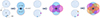 |
Fig. 1. Conceptual drawing illustrating the principle of dOTF. Left panel: depiction of a generic pupil with a single pupil modification near the bottom edge, along with a conceptual drawing of the dOTF contents and its location relative to the introduced pupil modification. Middle panel: similar to the depiction in the left panel, but with two pupil modifications present at the edge of the pupil. Right panel: similar to the depiction in the left panel, but with three pupil modifications at the edge of the pupil. The red circle represents the reflected and conjugated part of the pupil field image identified with the blue circle. The colors of the various pupil modifications are arbitrary and used for illustrative purposes only. |
As evident from Eq. (4), smaller pupil modification areas are advantageous; they contribute to achieving a higher resolution in the recovered wavefront phase map by minimizing the blurring effect. Additionally, obtaining a comprehensive measurement of ψ (across the entire pupil) necessitates the use of two dOTFs with distinct pupil modifications. Therefore, advocating for small pupil modifications further limits the influence of the overlap region, facilitating the construction of a complete measurement of the electric field across the entire pupil, but also helps avoid the need to use two dOTFs in certain situations.
3. Wavefront sensing using IFU spectroscopy
In this section, two methods for using dOTF to measure NCPAs over a broad spectrum with an IFU spectrograph are discussed. They make use of a phase probe for the dOTF process. This restriction is due to the advantages outlined in the previous section. Unlike pupil blockage (amplitude pupil modification), phase probing through actuator displacement offers a unique advantage: the ability to sense and correct NCPAs with a single system, the deformable mirror (DM).
3.1. Single-phase probe
Considering that DMs are routinely employed in high-contrast imaging, implementing pupil modifications using a DM actuator or segment poke is straightforward. A deformable mirror probe with a single actuator is particularly well suited, as the Gaussian-like poke influence function approaches the ideal Dirac function, minimizing the blurring effect because of the convolution product (however, deconvolution algorithm strategies exist; Knight et al. 2015; Jiang et al. 2019; Martinez & Dharmadhikari 2023). Additionally, DMs feature multiple points near the edge of the pupil, which introduces minimal blurring and enables the measurement of almost the entire pupil field. The availability of a DM in common-path optics instrument designs makes it simple to enable pupil modification for a dOTF measurement, where a single actuator displacement can be seen by all cameras in an instrument. For instance, considering the VLT/SPHERE (Beuzit et al. 2019), where the DM stands in the common-path infrastructure that feeds three scientific instruments (IRDIS, IFS, and ZIMPOL), it should be possible to calibrate the NCPAs between them.
3.1.1. Classical dOTF and IFU spectroscopy
A straightforward method for combining dOTF and IFU spectroscopy involves introducing pupil modification via a DM poke with an optimal displacement, denoted d, equal to λ/4 (taking into account the DM’s reflective nature and the round-trip propagation distance being twice the surface displacement; Codona 2013) at the shortest wavelength covered by the IFU spectrograph spectral range. In their work, Codona (2013) addressed the question of by how much a single actuator should be displaced in order to achieve the optimal dOTF signal, demonstrating that the dOTF amplitude is proportional to  , which reaches its first maximum when d = λ/4. Consequently, the author concluded that for optimal spatial resolution and maximum signal, a DM actuator displacement of λ/4 or less is advisable. In theory, dOTF should perform optimally under these conditions.
It is noteworthy that more than half of the maximum dOTF signal can be attained with an actuator displacement of λ/10. Leveraging this observation allows the proposal of a relatively simple implementation of dOTF with an IFU spectrograph, where the λ/4 poke at the shortest wavelength naturally corresponds to a smaller displacement at longer wavelengths, where the complex field can be measured at each wavelength of the data cube. Considering a hypothetical IFU spectrograph covering the spectral range from 600 nm to 2.4 μm, a λ/4 poke displacement translates into a λ/8 displacement at 1.2 μm (approximately 70% of the maximum dOTF signal) and λ/16 displacement at the longest wavelength. Constructing a dOTF data cube at any wavelength using two IFU spectrograph data cubes (one with the DM probe and one without) is theoretically feasible pending the spectral coverage expected.
3.1.2. Impact of the actuator displacement
However, signal-to-noise concerns must be addressed, especially as the poke displacement decreases. Rather than examining the effect of a λ/4 displacement across a broad spectral range, one can assess the effect of different actuator displacement values at a single wavelength (1.65 μm), which is formerly equivalent. A series of tests were conducted on the SPEED test bed (Martinez et al. 2022) using the active segmented mirror (ASM) of 163 segments. In Fig. 2, the theoretical dOTF signal amplitude is compared with the phase estimated for various segment poke displacements. These tests might be impacted by the large spatial extent of the segment used for the poke, but they highlight the fact that implementing this approach is unlikely to be an optimal solution: as the poke decreases, the estimation of the complex field becomes increasingly biased. With a λ/4 poke defined in the visible (632 nm) and a dOTF recorded in the near-infrared (1.65 μm), the root mean square (RMS) phase measurement conducted in the near-infrared – where the poke would be equivalent to approximately λ/10 displacement – shows a three-fold increase compared to a poke tailored to the wavelength (∼50 nm RMS vs. ∼140 nm RMS, as shown in Fig. 2). The optimal phase estimation using a λ/4 poke displacement at these two wavelengths is presented in Fig. 3. NCPAs initially caused a 50 nm RMS wavefront error. Through dOTF sensing and ASM compensation, this was reduced to 25 nm RMS, accounting for three nonresponding segments and ASM-related errors such as residual cophasing and segment focus errors.
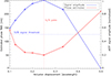 |
Fig. 2. dOTF signal amplitude (normalized, blue line) compared to the estimated dOTF phase (red line) for various poke displacements expressed in units of wavelength using the SPEED test bed ASM in the near-infrared. |
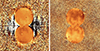 |
Fig. 3. dOTF phase measurements taken using the science camera with the SPEED test bed in the near-infrared (1.65 μm, left image) and visible (632 nm, right image). The segment poke displacement is λ/4 at the observing wavelength. Three locked segments of our ASM are visible in the images as bright or dark spots. |
3.2. Multiple and simultaneous phase probes
3.2.1. General principle
The preceding discussion advocates for an alternative implementation of dOTF with an IFU spectrograph, where an optimal dOTF signal (i.e., λ/4 poke displacement) is anticipated at each wavelength. A simple solution is to apply multiple successive phase pokes with displacements adapted to different wavelengths chosen within the spectral domain of the IFU spectrograph. However, this would require the generation of as many IFU spectrograph data cubes as there are involved pokes; indeed twice as many because, ideally, for each data cube that includes a pupil modification, a cube where the modification is absent is necessary. This solution is time consuming and therefore impractical.
Applying multiple pokes simultaneously is fundamentally not possible because the information from the complex field estimated by each probe overlaps in the dOTF. An example of two simultaneous pokes is presented in Fig. 1 (middle image), and the associated equations are presented below, where δM1 and δM2 represent two pupil modifications. In these circumstances, the dOTF can be given by
 (5)
(5)
and developed such that
 (6)
(6)
Equation (6) can be further developed and expressed as
 (7)
(7)
By excluding redundant information from Eq. (7), the impact of each phase probe becomes observable, although they will overlap in the dOTF signal. The orientation of the DM poke determines the orientation of the corresponding complex field in the dOTF (as indicated by the colors in Fig. 1, which aids in identifying the correspondence between probes and field measurements). The reasoning can be extended to more than two probes, as illustrated in the right image of Fig. 1, which shows the three-probe situation.
To address the overlap issue, an alternative implementation utilizes a circular variable filter (CVF) positioned in a conjugate pupil plane downstream from the DM (e.g., within a filter wheel, such as in a Lyot stop pupil plane). Circular variable filters are advanced-design interference narrow-pass filters deposited on circular substrates known as segments. The film thickness, and consequently the wavelength of peak transmittance, varies linearly and continuously with the angular position on the segment. CVF covering wavelengths ranging from the visible to the mid-infrared region of the spectrum are manufacturable for years. This setup enables multiple DM pokes to be observable at specific wavelengths. In this scenario, in Fig. 1, the colors of the probes would correspond to a displacement of λ/4 defined at various wavelengths. This approach allows the generation of multiple DM pokes simultaneously and their use for dOTF through the IFU spectrograph data cubes, which are constantly optimized in dOTF signal. The fundamental principles of using multiple and simultaneous phase probes for dOTF with IFU are depicted in Fig. 4. The possibilities in terms of the number of probes are vast and only limited by the number of actuators at the edge of the DM pupil, taking into account a certain distance between them. The pokes are then defined in displacement in such a way that the dOTF signal is maximal at the desired wavelength. Optimization work is necessary on the selection of the number of pokes and probes and the choice of wavelength to define their displacement.
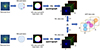 |
Fig. 4. Conceptual illustration depicting the process of combining dOTF wavefront sensing involving multiple DM phase probes simultaneously to acquire a dOTF data cube from two IFU spectrograph data cubes. |
In the design proposed in Fig. 4, the CVF is annular in order to only have spectral effects on a ring around the edge of the pupil where the DM pokes are located, leaving the majority of the pupil surface without spectral filtering. This unfiltered area defines the zone within which the dOTF will be effective in measuring the complex field. However, the small unmeasured annular zone is of little or no importance, as it is subsequently filtered by the Lyot stop in coronagraphic imaging.
3.2.2. Combining spectral bands
As the dOTF is sensitive to phase wrapping, it cannot measure wavefront phase errors larger than 2π, which are equivalent to mirror surface errors larger than λ/2. Leveraging the IFU spectroscopy capability in conjunction with the multiple and simultaneous phase probe technique makes it straightforward to extend the phase wrapping range using two sets of dOTF measurements in two different wavelength bands (Dancey 1979). With two measured wavelengths, λ1 and λ2, the phase wrapping from an optical path difference of a single wavelength λ is extended to the synthetic wavelength ∧ = λ1λ2/|λ2 − λ1|. The possibility, through IFU spectroscopy, of measuring the dOTF at two closely spaced wavelengths is extensive, meaning that multiple sets of two closely spaced wavelengths can be used.
4. Conclusion
Given their relevance to large telescopes with high light-gathering power and unprecedented spatial resolution enabled by adaptive optics, most new extremely large telescopes (de Zeeuw et al. 2014; Sanders 2013) will be equipped with IFUs (e.g., Thatte et al. 2022; Marconi et al. 2022). The multiple and simultaneous phase probe dOTF, which involves a DM and a CVF in pupil planes, presents a way to harness the advantages of both dOTF and the IFU spectrograph. This approach requires minimal investment because all instruments using IFU spectrography are installed on telescopes equipped with AO systems where a DM is readily available, and the CVF is a commercially available component. The approach presented here can be used in two ways: (i) as an internal calibration tool for NCPA before on-sky operations, and (ii) as part of NCPA’s on-sky calibration and maintenance strategy. However, implementing it effectively would demand dedicated efforts to assess the impact of AO performance reduction when using the AO DM for dOTF. This would entail temporarily adjusting the wavefront sensor to prevent correction for the multiprobe impacts and excluding the actuators involved in the dOTF from the AO correction process.
As first-light instruments for ELTs have not yet reached the stage where new changes to hardware or systems may be introduced, and because most of them incorporate a coronagraphic arm, adding a CVF to a filter wheel is easily achievable. Anticipating on-sky implementation becomes more manageable with a dedicated DM for both the dOTF probes and NCPA correction, thereby circumventing the potential limitations mentioned above.
There are three major types of IFU systems, namely lenslets, fibers, and image slicers, with the most efficient fiber system using lenslets coupled to the fibers (e.g., Lovis et al. 2022; Marconi et al. 2022). A detailed analysis of fiber-based systems is required in order to assess the impact of fiber filtering on the dOTF, but this falls beyond the scope of this Letter, which is simply meant to introduce the concept.
References
- Anagnos, T., Trappen, M., Tiong, B. C. K., et al. 2021, Appl. Opt., 60, D108 [NASA ADS] [CrossRef] [Google Scholar]
- Beuzit, J. L., Vigan, A., Mouillet, D., et al. 2019, A&A, 631, A155 [NASA ADS] [CrossRef] [EDP Sciences] [Google Scholar]
- Boccaletti, A. 2021, European Planetary Science Congress, EPSC2021–24 [Google Scholar]
- Codona, J. L. 2012, in Adaptive Optics Systems III, eds. B. L. Ellerbroek, E. Marchetti, & J. P. Véran, SPIE Conf. Ser., 8447, 84476P [NASA ADS] [Google Scholar]
- Codona, J. L. 2013, Opt. Eng., 52, 097105 [CrossRef] [Google Scholar]
- Codona, J. L., & Doble, N. 2015, J. Astron. Telesc. Instrum. Syst., 1, 029001 [NASA ADS] [CrossRef] [Google Scholar]
- Crepp, J., Pueyo, L., Brenner, D., et al. 2011, ApJ, 729, 132 [NASA ADS] [CrossRef] [Google Scholar]
- Dancey, R. 1979, J. Roy. Astron. Soc. Can., 73, 158 [NASA ADS] [Google Scholar]
- de Zeeuw, T., Tamai, R., & Liske, J. 2014, The Messenger, 158, 3 [NASA ADS] [Google Scholar]
- Groff, T., Kasdin, N. J., & Peters, M. A. 2013, Proceedings of the 2013 IEEE Aerospace Conference, 200 [Google Scholar]
- Jiang, F., Ju, G., Qi, X., & Xu, S. 2019, Opt. Lett., 44, 4283 [NASA ADS] [CrossRef] [Google Scholar]
- Knight, J. M., Rodack, A. T., Codona, J. L., Miller, K. L., & Guyon, O. 2015, in Techniques and Instrumentation for Detection of Exoplanets VII, ed. S. Shaklan, SPIE Conf. Ser., 9605, 960529 [NASA ADS] [CrossRef] [Google Scholar]
- Kuhn, J. R., Potter, D., & Parise, B. 2001, ApJ, 553, L189 [NASA ADS] [CrossRef] [Google Scholar]
- Lovis, C., Blind, N., Chazelas, B., et al. 2022, in Ground-based and Airborne Instrumentation for Astronomy IX, eds. C. J. Evans, J. J. Bryant, & K. Motohara, SPIE Conf. Ser., 12184, 121841Q [NASA ADS] [Google Scholar]
- Macintosh, B., Graham, J., Palmer, D., et al. 2006, in Advances in Adaptive Optics II, eds. B. L. Ellerbroek, & D. Bonaccini Calia, SPIE Conf. Ser., 6272, 62720L [NASA ADS] [CrossRef] [Google Scholar]
- Marconi, A., Abreu, M., Adibekyan, V., et al. 2022, in Ground-based and Airborne Instrumentation for Astronomy IX, eds. C. J. Evans, J. J. Bryant, & K. Motohara, SPIE Conf. Ser., 12184, 1218424 [NASA ADS] [Google Scholar]
- Marois, C., Doyon, R., Racine, R., et al. 2005, J. Roy. Astron. Soc. Can., 99, 130 [NASA ADS] [Google Scholar]
- Marois, C., Lafrenière, D., Doyon, R., Macintosh, B., & Nadeau, D. 2006, ApJ, 641, 556 [Google Scholar]
- Martinez, P., & Dharmadhikari, R. 2023, A&A, 680, L12 [NASA ADS] [CrossRef] [EDP Sciences] [Google Scholar]
- Martinez, P., Beaulieu, M., Gouvret, C., et al. 2022, in Ground-based and Airborne Instrumentation for Astronomy IX, eds. C. J. Evans, J. J. Bryant, & K. Motohara, SPIE Conf. Ser., 12184, 121843W [NASA ADS] [Google Scholar]
- Sanders, G. H. 2013, JApA, 34, 81 [NASA ADS] [Google Scholar]
- Thatte, N. A., Melotte, D., Neichel, B., et al. 2022, in Ground-based and Airborne Instrumentation for Astronomy IX, eds. C. J. Evans, J. J. Bryant, & K. Motohara, SPIE Conf. Ser., 12184, 1218420 [NASA ADS] [Google Scholar]
All Figures
|
Fig. 1. Conceptual drawing illustrating the principle of dOTF. Left panel: depiction of a generic pupil with a single pupil modification near the bottom edge, along with a conceptual drawing of the dOTF contents and its location relative to the introduced pupil modification. Middle panel: similar to the depiction in the left panel, but with two pupil modifications present at the edge of the pupil. Right panel: similar to the depiction in the left panel, but with three pupil modifications at the edge of the pupil. The red circle represents the reflected and conjugated part of the pupil field image identified with the blue circle. The colors of the various pupil modifications are arbitrary and used for illustrative purposes only. |
| In the text | |
|
Fig. 2. dOTF signal amplitude (normalized, blue line) compared to the estimated dOTF phase (red line) for various poke displacements expressed in units of wavelength using the SPEED test bed ASM in the near-infrared. |
| In the text | |
|
Fig. 3. dOTF phase measurements taken using the science camera with the SPEED test bed in the near-infrared (1.65 μm, left image) and visible (632 nm, right image). The segment poke displacement is λ/4 at the observing wavelength. Three locked segments of our ASM are visible in the images as bright or dark spots. |
| In the text | |
|
Fig. 4. Conceptual illustration depicting the process of combining dOTF wavefront sensing involving multiple DM phase probes simultaneously to acquire a dOTF data cube from two IFU spectrograph data cubes. |
| In the text | |
Current usage metrics show cumulative count of Article Views (full-text article views including HTML views, PDF and ePub downloads, according to the available data) and Abstracts Views on Vision4Press platform.
Data correspond to usage on the plateform after 2015. The current usage metrics is available 48-96 hours after online publication and is updated daily on week days.
Initial download of the metrics may take a while.