| Issue |
A&A
Volume 675, July 2023
|
|
|---|---|---|
| Article Number | A38 | |
| Number of page(s) | 11 | |
| Section | Interstellar and circumstellar matter | |
| DOI | https://doi.org/10.1051/0004-6361/202141840 | |
| Published online | 30 June 2023 | |
Dust dynamics in current sheets within protoplanetary disks
I. Isothermal models including ambipolar diffusion and Ohmic resistivity
1
Université Paris-Saclay, Université Paris Cité, CEA, CNRS, AIM,
91191
Gif-sur-Yvette, France
e-mail: This email address is being protected from spambots. You need JavaScript enabled to view it.
2
École normale supérieure de Lyon, CRAL, UMR CNRS 5574, Université de Lyon,
46 allée d Italie,
69364
Lyon Cedex 07, France
3
Department of Astrophysics, American Museum of Natural History,
Central Park West at 79th Street,
New York, NY
10024, USA
4
Department of Earth and Planetary Sciences, American Museum of Natural History,
Central Park West at 79th Street,
New York, NY
10024, USA
Received:
21
July
2021
Accepted:
25
May
2023
Abstract
Context. Chondrules originate from the reprocessing of dust grains. They are key building blocks of telluric planets, yet their formation, which must happen in strongly localized regions of high temperature, remains poorly understood.
Aims. We examine the dust spatial distribution near regions of strong local heating produced by current sheets, as a step toward exploring a potential path for chondrule formation. We further aim to investigate current sheet formation under various conditions in protoplanetary disks in the presence of ambipolar diffusion and Ohmic resistivity and the effect of current sheet morphology on dust dynamics in their vicinity.
Methods. We used the RAMSES code including modules for nonideal magnetohydrodynamics and the solution of the dynamics of multiple sizes of dust grains to compute unstratified shearing box simulations of current sheet formation. Through seven models, we investigated the effect of the ambipolar diffusion and Ohmic resistivity strength, the initial density, and magnetic field, as well as the resolution and box size.
Results. We find that current sheets form in all our models, with typical widths of 10−3–10−2 AU, and that strong dust fraction variations occur for millimeter-sized grains. These variations are typically of an order of magnitude and up to two orders of magnitude for the most favorable cases. We also show that the box size and resolution has a strong impact on the current sheet distribution and intensity.
Conclusions. The formation of current sheets that can intensely heat their surroundings near strong dynamical dust fraction variations could have important implications for chondrule formation, as it appears likely to happen in regions with a large dust fraction.
Key words: hydrodynamics / magnetohydrodynamics (MHD) / turbulence / protoplanetary disks / interplanetary medium / planets and satellites: formation
© The Authors 2023
 Open Access article, published by EDP Sciences, under the terms of the Creative Commons Attribution License (https://creativecommons.org/licenses/by/4.0), which permits unrestricted use, distribution, and reproduction in any medium, provided the original work is properly cited.
This article is published in open access under the Subscribe to Open model. This email address is being protected from spambots. You need JavaScript enabled to view it. to support open access publication.
1 Introduction
The rock content of the Solar System primarily originates from interstellar dust. The earliest rocks that formed in the Solar System, chondrites, were highly processed during early disk evolution. Chondrites are the most frequently found type of meteorites (around 80% by mass). In these meteorites, the chondrules represent 20–80% of the mass. They are surrounded by a matrix of fine grains that are more numerous than chondrules. The chondrules are spherical silicate grains of 0.1−1 mm with a glassy texture (Jones et al. 2005). To constrain the physical conditions at play in protoplanetary disks, it is essential to find a mechanism common enough to explain chondrule formation that can reproduce their apparent abundance in the Solar System.
Chondrule textures indicate that they form during rapid heating and cooling events called flashes. These must meet at least four prerequisites: they must have extremely short heating timescales (less than a few minutes, Connolly & Love 1998); be very localized so that the chondrules can exit them rapidly (Hubbard & Ebel 2015); be energetic enough to increase the grain temperature up to ~ 1700–2000 K (Lofgren & Lanier 1990; Radomsky & Hewins 1990; Hewins & Connolly 1996); and, compared to the free-space cooling time of chondrule-sized objects of a few seconds, the cooling rate in and near these flashes must be relatively slow (≈102–103 K h−1 Radomsky & Hewins 1990). The abundance of chondrules is evidence that these flashes, no matter how and where they occur, are common enough to turn a large fraction of the dust into chondrules.
A significant fraction of chondrules have multiple rims that must have formed in repeated flashes during their formation (Barosch et al. 2020). Chondrule formation theories must also explain their narrow range of sizes (0.1−1 mm, Jacquet 2014; Friedrich et al. 2015), their diversity of compositions, and the presence of a volatile-rich matrix (Ebel et al. 2018). The evidence for complementarity suggests a reservoir of common origin for the chondrules and the matrix (Palme et al. 2015; Bland et al. 2005). Nevertheless, the matrix grains are clearly different from chondrules in terms of composition and size. They contain a substantial abundance of volatiles that would evaporate at temperatures higher than 500–800 K, which indicates that they do not experience any dramatic heating events. In addition, the matrix is mostly composed of fine ≲5µm grains. Whether it is a by-product of chondrule formation (Huss et al. 2005) or a population that experiences a totally different evolution, the matrix and chondrule formation are intrinsically related (Ebel et al. 2018). Last but not least, high dust concentrations seem required to explain the volatile abundances (Alexander et al. 2008) in chondrules, which suggests that their precursors should be able to concentrate preferentially while the matrix would stay well coupled to the gas.
Magnetic fields in protoplanetary disks have been widely studied as a possible source of angular momentum transport via the magnetorotational instability (hereafter MRI, Balbus & Hawley 1991; Stone et al. 1996; Sano et al. 2000, among others). As disks are in fact poorly ionized, the MRI could be inhibited in disk midplanes in the so-called dead zones (Gammie 1996; Fleming et al. 2000). More recent studies have suggested that it might even be suppressed entirely in disks, with the angular momentum carried away instead by magnetocentrifugal winds (Bai & Stone 2013; Lesur et al. 2014). An imperfect coupling between the neutral and the magnetic field, however, might give birth to dissipative structures (Brandenburg & Zweibel 1994).
An interesting hypothesis for chondrule formation is that it occurs in or around thin current sheets (Joung et al. 2004). These dissipative structures are believed to occur because of finite electric conductivity (Parker 1972, 1994; Joung et al. 2004). The resistive heating might be efficient enough in current sheets so that dust grains reach their melting temperatures (McNally et al. 2014). In addition, it was shown by Hubbard et al. (2012) that the increase in the temperature could produce resistivity gradients that make the sheets thinner, making them a potentially favored place for chondrule formation.
Recent studies have started to investigate dust dynamics in resistive disks (Riols & Lesur 2018; Riols et al. 2020). However, the dust behavior at the smaller scales of current sheets remains essentially unexplored. In addition, current sheet formation with Ohmic resistivity has been investigated in the unstratified shearing box models of McNally et al. (2014) and more recently by Ross & Latter (2018); however, the effect of ambipolar diffusion on current sheet formation has not been investigated. In this work (paper I), we aim to understand the dynamical sorting of dust grains in the vicinity of current sheets. Moreover, we want to investigate current sheet formation in the presence of both ambipolar diffusion and Ohmic dissipation. With that in mind, we performed simulations of dissipative current sheet formation using the shearing box (Colling et al. 2018) and dust dynamics modules (Lebreuilly et al. 2019) of the RAMSES code (Teyssier 2002; Fromang et al. 2006).
This manuscript is organized as follows. In Sect. 2, we detail the theoretical framework used in this study. After that, we explain our solution method in Sect. 3. Then, in Sect. 4, we introduce and describe the different models that we computed. Following this, we discuss our results in Sect. 5 and finally present our conclusion and prospects in Sect. 5.4.
2 Theoretical framework
2.1 Gas and dust coupling
We describe gas and dust mixtures with a monofluid approach in the terminal velocity approximation (see Laibe & Price 2014a,b,c; Hutchison et al. 2018; Lebreuilly et al. 2019, 2020, for more details on gas and dust monofluids). The mixture of density ρ is composed of a plasma (neutral atoms, ions, and electrons) and neutral dust grains. The plasma has a density ρ and velocity v and the dust fluids each have a density ρk and velocity vk ≡ v + wk, where wk is the differential velocity between the dust and the plasma.
2.2 Dusty nonideal MHD for neutral grains
Around T-Tauri stars, the disk mass is much smaller than the mass of the star, so one can neglect the self-gravity of the disk. In this context, the equations of magnetohydrodynamics (MHD) with 𝒩 neutral dust species denoted by index k can be written as
![Mathematical equation: $\matrix{ {{{\partial \rho } \over {\partial t}} + \nabla \cdot \left[ {\rho {\bf{v}}} \right]} \hfill & = \hfill & {0,} \hfill \cr {{{\partial {\rho _k}} \over {\partial t}} + \nabla \cdot \left[ {{\rho _k}\left( {{\bf{v}} + {{\bf{w}}_{\bf{k}}}} \right)} \right]} \hfill & = \hfill & {0,\forall k \in \left[ {1,N} \right],} \hfill \cr {{{\partial \rho {\bf{v}}} \over {\partial t}} + \nabla \cdot \left[ {\left( {{P_{\rm{g}}} + {{{{\bf{B}}^2}} \over 2}} \right) + \rho \left( {{\bf{v}} \otimes {\bf{v}}} \right) - {\bf{B}} \otimes {\bf{B}}} \right]} \hfill & = \hfill & { - \rho {\bf{g}},} \hfill \cr {{{\partial {\bf{B}}} \over {\partial t}} - \nabla \times \left[ {{\bf{v}} \times {\bf{B}}} \right]} \hfill & = \hfill & { - \nabla \times {{\bf{E}}_{\bf{p}}},} \hfill \cr {\nabla \cdot {\bf{B}}} \hfill & = \hfill & {0,} \hfill \cr } $](/articles/aa/full_html/2023/07/aa41840-21/aa41840-21-eq1.png) (1)
(1)
where Pg is the gas pressure, B is the magnetic field, g is the gravitational acceleration, and where the dust differential velocity for each species k is given by (Lebreuilly et al. 2020)
![Mathematical equation: ${{\bf{w}}_{\bf{k}}} \equiv \left[ {{\rho \over {\rho - {\rho _k}}}{t_{{\rm{s,}}k}} - \sum\limits_{l = 1}^N {{{{\rho _l}} \over {\rho - {\rho _l}}}{t_{{\rm{s}}{\rm{.}}l}}} } \right]{{\nabla {P_{\rm{g}}} - {\bf{J}} \times {\bf{B}}} \over \rho },$](/articles/aa/full_html/2023/07/aa41840-21/aa41840-21-eq2.png) (2)
(2)
where J ≡ ∇ × B is the electric current. The stopping time (Epstein 1924)
 (3)
(3)
where grain species k has radius sgrain,k. Neglecting the Hall effect because it does not dissipate energy, as ((∇ × B) × B) • (∇ × B) = 0, the electric field in the comoving frame of the plasma (i.e., everything except the dust)
 (4)
(4)
where ηO and ηA are the Ohmic and ambipolar resistivities. At this point, let us also recall the definition of the plasma parameter
 (5)
(5)
2.3 Unstratified shearing box approximation
Modeling the protoplanetary disk as a whole is computationally expensive, especially when attempting to resolve thin current sheets. Fortunately, a simple approximation can be made when considering only a small part of the disk. In the shearing box approximation (Hawley et al. 1995), we only model a small volume of the disk at a radius R0 with a length L0 ≪ R0 typically of a few scale heights H and in rotation at the Keplerian velocity Ωkep(R0)1. In this context and neglecting the vertical stratification of the disks, the total momentum conservation equation becomes (Hawley et al. 1995)
![Mathematical equation: ${{\partial \rho {\bf{v}}} \over {\partial t}} + \nabla \cdot \left[ {\rho {\bf{v}} \otimes {\bf{v}} + \left( {{P_{\rm{g}}} + {{{{\bf{B}}^2}} \over 2}} \right) + {\bf{B}} \otimes {\bf{B}}} \right] = - 2\rho {\bf{\Omega }} \times {\bf{v}} + \rho {\bf{g}},$](/articles/aa/full_html/2023/07/aa41840-21/aa41840-21-eq6.png) (6)
(6)
where g = −2qΩ2x, and x is the position along the radial axis. The parameter q depends on the radial profile of the disk angular velocity and is equal to 3/2 in the Keplerian case. The term −2ρqΩ2x represents the centrifugal pseudo-force and −2ρΩ × v is the Coriolis pseudo-force.
2.4 Elsasser numbers
At this stage it is useful to define the Elsasser numbers Am and Λ of the ambipolar and Ohmic diffusion, respectively2. They quantify the relative importance of resistive effects and Alfvén wave propagation and are defined as
 (7)
(7)
where  is the Alfvén speed. In this work, we use these numbers to impose the initial values of the resistivities. According to these definitions of the Elsasser numbers the corresponding resistivity (either ηA or ηo) is
 (8)
(8)
We consider two values for the Elsasser numbers to model strong (Els = 1) and weak (Els = 10) resistivity cases. These values are typical for protoplanetary disks interiors (see the recent review by Lesur 2021a, and references therein).
Physically, the resistivity is determined by the complex interplay between ionization and recombination on dust grains and in the gas (e.g., Desch & Turner 2015). However, by setting fixed Elsasser numbers, we can examine how current sheets behave in the regime where resistivity is important enough to produce heating but not so dominant that it suppresses the formation of current sheets.
2.5 Resistive heating
The Ohmic and ambipolar resistivities each introduce a heating term in the energy equation
 (9)
(9)
In this preliminary study, we use the isothermal approximation for the gas, so these terms are not included in the calculation but instead estimated in post-processing.
2.6 Magnetorotational instability
In magnetized disks, the interplay between the differential rotation and the tension of the magnetic field lines can lead to the MRI (Balbus & Hawley 1991). In the ideal MHD case, where the coupling between the fluid and the magnetic field is perfect, one finds the wavelength for the fastest growing mode in terms of the scale height (Hawley et al. 1995; Bai & Stone 2011)
 (10)
(10)
When the resistive effects are important, the expression for the wavelength of the fastest growing mode is modified. In the ambipolar case it is (Wardle 1999; Bai & Stone 2011)
 (11)
(11)
This rough estimate of  allows us to determine if the simulation box that we use is comfortably larger than the fastest growing mode, as is necessary to properly capture the MRI.
2.7 Angular momentum transport
The usual way to estimate the transport of angular momentum in protoplanetary disks is to compute the viscosity parameter (Shakura & Sunyaev 1976)
 (12)
(12)
where ur and uϕ are the radial and azimuthal components of the gas velocity relative to the shear. Typically, α < 1 in the case of resistive MRI and can be much smaller if the instability is damped. To compare the models, we measure  , which is the time averaged α over the last 10 Ω−1 of the run to make sure that the saturated regime of the turbulence is reached and that the measure is not affected by the initial conditions.
2.8 Current sheet analysis
Following Ross & Latter (2018), we define Ohmic and ambipolar current sheets as regions of strong dissipation. We compute the following quantities
 (13)
(13)
In the rest of this work, and similarly to Ross & Latter (2018), we define a region of strong dissipation due to a nonideal effect θ (with θ = O for Ohmic or A for ambipolar) as
 (14)
(14)
Those regions thus have dissipation rates more than three standard deviations above the average value.
3 Numerical methods
3.1 Numerical scheme
In this work, we use the RAMSES code (Teyssier 2002; Fromang et al. 2006) and its dust dynamics solver (Lebreuilly et al. 2019) extended to neutral grains in MHD by Lebreuilly et al. (2020). We also use the implementation of ambipolar diffusion and Ohmic resistivity of Masson et al. (2012).
We integrate Eqs. (1) replacing the momentum equation by Eq. (6). We use the MUSCL scheme of RAMSES with the HLLD Riemann solver for the barycenter part of the MHD equations and for the induction equation (Miyoshi & Kusano 2005). For stability and similarly to Fromang et al. (2013), the solver automatically switches to a Lax–Friedrichs solver where β < 10−3. As in Fromang et al. (2013) and again for stability reasons, we use the multidimensional slope limiter of Suresh (2000) for the barycenter part of the conservation equations. Similarly to Colling et al. (2018), we use an operator-splitting and an implicit Crank-Nicholson scheme to take into account the shear source terms in Eq. (6) without adding any constraint on the stability of the scheme. For the dust differential advection term, we use the dust solver of Lebreuilly et al. (2019, 2020) with the minmod slope limiter.
When regions of very small density form in a model, they can lead to very large Alfvén velocities and hence very small timesteps. When this happens, evolving the model significantly in a reasonable computational time becomes impossible. To circumvent this issue, we impose an adaptive density floor that prevents β from dropping below the value βmin = 10−4. This requires that the density be
 (15)
(15)
We point out that this method is strictly equivalent to imposing a maximum Alfvénic Mach number. We verified that the total box mass is not much affected throughout the calculation as it is conserved within about 1% in all models.
We impose a maximum dust differential velocity of 5 km s−1 everywhere in the box to avoid unrealistically large dust velocities or new constraints on the timestep. This value is safely higher than the gas sound-speed which is around 1 km s−1 and is typically only reached in regions of very low densities. In such low density regions, the terminal velocity approximation no longer holds. For safety, we also enforce the maximum Stokes number to be 0.3 by setting
 (16)
(16)
This is similar to the method of Ballabio et al. (2018), but we use the Stokes number while their regularization was based on the stability condition of their scheme.
Summary of the different simulations.
3.2 Setup
We impose a uniform initial density (10−11 g cm−3) and a uniform initial temperature of 300 K. The initial magnetic field is vertical with β0 = 750, except for the O10A10BETA7500 run, which is initialized with β0 = 7500. Unless specified, these models have a box size of one scale height, that is 0.05 AU, as all the models are computed at R0 = 1 AU and we assume H/R = 0.05.
All the models are computed in the isothermal and unstratified shearing box approximations.
In all the runs, we consider three dust sizes of 10 µm (St = 4 × 10⁻⁴), 100 µm (St = 4 × 10⁻³), and 1 mm (St = 4 × 10⁻²), with initial dust ratios of 1/300. This leads to a total dust-to-gas ratio of 1/100. We choose not to explore the behavior of grains smaller than a micron because they would be strongly coupled with the gas (similarly to what we already observe for the 10 µm grains). In addition, we do not study larger grains because the largest chondrules are smaller than a few millimeters (Friedrich et al. 2015). All the dust grains have an intrinsic grain density of 3 g cm−3 which is in line with the typical density of chon-drules (e.g., Hughes 1980; Jacquet 2014; Friedrich et al. 2015). We note that initial dust concentration is unimportant as long as the dust back−reaction is weak, so we present the relative dust fraction variations  in this study rather than the actual dust fractions e of the models.
The initial ambipolar and Ohmic resistivities are uniform and imposed by setting the value of the Elsasser numbers. Throughout the run, the Ohmic resistivity stays constant. The ambipolar resistivity however varies, as it scales ∝|B2| (see Eq. (4)). To avoid very small timesteps, we cap the value of the resistivities by the value 10ΩH2 as was done by Lesur et al. (2014).
In all models, azimuthal and vertical boundaries are treated as simple periodic boundaries. The radial boundaries are, however, treated according to the shearing box implementation of Colling et al. (2018) that we adapted to Keplerian rotation by setting q = 3/2.
4 Results
In this section, we describe our models, which are summarized in Table 1, where we provide their initial conditions along with some measured quantities.
4.1 Fiducial run
Our fiducial model, run 010 A10, is computed at R = 1 AU, as are all models, and the initial ambipolar and Ohmic Elsasser numbers are both set to 10. Figure 1 shows a three-dimensional rendering of the current magnitude for our fiducial model at the end of the simulation. As can be seen, due to the moderately low resistivities, quite strong turbulence develops in this model, with  . This value is higher than the value of ≈2–3 × 10⁻² from the previous study of Bai & Stone (2011). The difference most likely comes from the use of a 4H × 4 H × 4H box in their case. This is consistent with what we find in Sect. 4.2 where we explore a larger box and find
  . There are strong local variations of β ranging from ~0.05 to ~1000 and we clearly see sheet-like structures approximately located in the x–y plane. These sheets have a typical width of ~10−3 AU ≈ 1.5 × 10⁵ km which is about the same order of magnitude as previous estimates (Joung et al. 2004), but is also roughly 4∆x. We can thus wonder whether the current structures are fully resolved, which we discuss below in Sect. 4.2.
In Fig. 2, we show slices of the relative dust fraction variations for the 10 µm (top), 100 µm (middle) and 1 mm grains (bottom) for five of the models we computed. The same color scale is used for all grain sizes to best display the range of variation of dust fraction for the 1 mm grains. As can be seen, these grains experience strong dynamical sorting. Their dust fraction indeed increases up to almost two orders of magnitude in a small fraction of the volume. Smaller 100 µm grains also experience significant, although less important, dust fraction variations of as much as an order of magnitude. The dust fraction variations of 10 µm grains are, however, much smaller (about ±10% at most).
Dust grains tend to be depleted in current maxima. This is actually expected, if we consider a plasma with a strong electric current. In this case, the differential dust velocity can be approximated as wk ≈ −ts,k(J × B)/ρ. Generally, dust thus tends to be repelled from the peak of a current sheet where the dust drift velocity reaches a maximum and also flips its direction. This expulsion mechanism is illustrated in Fig. 3. However, similarly to dust motion in pressure bumps in the case without a magnetic field, here, we expect the grains to be trapped where ∇Pg = J × B. If two current sheets neighbor each other, then those traps are necessarily between them. We note that this concentration mechanism does not prevent the grains from being completely removed from strongly heated regions because of thermal diffusion and because the ambipolar heating source term ||J × B||2/||B||2, which we show below dominates the heating, does not have the same morphology as ||J||.
In Fig. 4, we display the histogram of the dust fraction as a function of the ambipolar and Ohmic heating parameters ΓA and ΓO, with the colors representing the integrated mass relatively to the total box mass. In the top, right panel, we see that the bulk of the mass of the millimeter-sized dust grains resides in regions of moderate heating although large dust fractions that seem likely to be necessary for chondrule formation are found at a wide range of values of ΓA. As explained earlier, the dust fraction variations of small 10 µm grains are much smaller. There is no significant preferential sorting of these grains (left panels). As can be seen, the heating source term due to ambipolar diffusion dominates strongly over the Ohmic source term ηo||J||2 for our fiducial model. This is also true for the other models (see Table 1). This effect was previously observed by Joung et al. (2004), who noted that the ambipolar heating term could exceed the Ohmic one by over an order of magnitude. This could have a strong impact on chondrule formation since the Ohmic dissipation rates observed by Joung et al. (2004) are similar to ours and were already sufficient to produce significant temperature variations up to values of ~1500 K. This however depends on the treatment of the cooling, that is to say the values of the opacity, which in turns depend on the abundance and properties of dust grains.
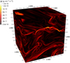 |
Fig. 1 Three-dimensional rendering of the current magnitude for our fiducial model O10A10 (t = 50 Ω−1). |
4.2 Numerical convergence and box size
We now discuss the impact of the box size and resolution by introducing two additional models, runs O10A10-LARGE and O10A10-HR. The first one, run O10A10-LARGE, is the same as the fiducial model, run 010A10, but with a twice as large box, using a 2563 grid to maintain constant resolution. The second model, 010A10-HR, is computed with the same box size as the fiducial model, but using a 2563 grid to double the numerical resolution. As O10A10-HR is computationally expensive because of the quadratically reduced ambipolar diffusion timestep, we compare the three models at t = 20 Ω−1.
Figures 5a and b show that, although the three models are qualitatively similar, they show some notable differences. First, we see that increasing the box size seems to lead to a more homogeneous current sheet distribution. This suggests that the two dominant current sheets observed in the fiducial model might be of numerical origin. As noted in previous studies of MRI turbulence in shearing box simulations, increasing the box size leads to less efficient turbulent transport, which is also why the dust fraction variations are smaller in run O10A10-LARGE (the dust fraction increases by a factor up to 18, against ~56 for the fiducial run and ~51 for O10A10-HR). This is in line with the fact that  for O10A10-LARGE, which is about 3 times smaller than for the fiducial run. This particular and essential detail encourages future calculations that should consider current sheet formation but in a larger scale environment. This could be done either with stratified shearing boxes, as we plan to do in future investigations, or in global calculations, for which the achievable resolution remains largely insufficient.
In terms of resolution, a comparison of run O10A10-HR with our fiducial one seems to indicate that we are approaching convergence both in terms of thickness of the current sheets, which is not a factor of two smaller in run O10A10-HR at twice the resolution, and also in terms of the range of variations for the current norm (the peak current at t = 20Ω−1 is 1.5 × 10⁻¹⁰ g cm−2 s−2 for O10A10-HR, compared to 1.4 × 10⁻¹⁰ g cm−2 s−2 in the fiducial run) and dust fraction (the dust ratio increases up to a factor of ~50–60 for O10A10-HR and O10A10). However, in terms of spatial distribution of the current sheets, increasing the resolution seems to have a similar effect as increasing the box size. As can be seen, current sheets are more evenly distributed in model 010A10-HR than they are in the fiducial model. We show in Sect. 5.1 that this only has a little effect on the probability distribution functions of the dust in the current sheets.
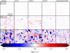 |
Fig. 2 Edge-on slices of the relative dust fraction variations for O10A10 (fiducial run), O1A1, O10A1 and O1A10 (more resistive runs), from left to right. The slices are displayed at t ~ 8 yr (~50 Ω−1), except for run O 10A10BETA7500 for which they are displayed at t ~ 32 yr (~200 Ω−1). The dust grain size increases from top to bottom. |
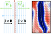 |
Fig. 3 Cartoon illustrating the decoupling of the gas and dust near a current sheet. Left: schematic local view of a current sheet and the dust drift velocity in its vicinity; B is the magnetic field, J is the electric current and wk is the dust drift velocity. Right: dust ratio variation near a current sheet (zoom in and 90 degree rotation of the left snapshot of Fig. 5; the color scale is the same, with red high and blue low). The dotted line shows the approximate (hand drown) position of the current sheet, the white arrow represent the drift velocity (green) and J × B (black) direction projected in the plane of the slice. |
4.3 Impact of the resistivity
We next explore the impact of the value of the resistivities with model O1A1, where the two Elsasser numbers are set to unity (and hence the model is more resistive than our fiducial one). Figure 6 shows that this model forms current sheet structures as in the fiducial run. In the case of run O1A1 however, these sheets are wider than for the fiducial case with a typical thickness of ~2 × 10⁻³ AU. A thickening of the current structures is expected with increasing resistivity. Indeed, as the ambipolar length increases, the magnetic field lines are rearranged over larger scales. As expected, the MRI turbulence is weaker in 01A1 than in the fiducial case. We measure  , which is about one order of magnitude smaller than the fiducial value.
Local variations of the dust fraction for the 100 micron-and millimeter-size grains are similar to those of run O10A10 although not as strong can be seen in Fig. 2. Moreover, the regions of high dust fraction are thicker in this model because the width of the current sheets is larger than in model O10A10. In this model, the dust still tends to be expelled from regions of maximal current. However, as explained earlier this does not necessarily mean that dust is expelled from regions of high dissipation by ambipolar diffusion. As in the fiducial model, small 10 µm grains remain well coupled to the gas everywhere in the box and their variation of concentration is insignificant.
We also computed two additional models O10A1 and O1A10, where the two Elsasser number are different (Λ = 10 and Am = 1 for O10A1 and the opposite for O1A10). We still form current sheets which, as expected, are intermediate in size between O10A10 and O1A1. For the same reasons, the dust concentration variations are also stronger in these two additional models than in O1A1 and less important than in O10A10. For the same reason as for O1A1, the turbulence is also weaker for O1A10 and O10A1.
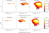 |
Fig. 4 Histogram of the dust fraction e as a function of the ambipolar and Ohmic heating source terms for the 10 µm (left), 100 µm (middle) and 1 mm grains (right) for the O10A10 model at t = 50 Ω−1. The colors represent the integrated total mass (the color bar is log-scaled). We note that the heating is dominated by ambipolar diffusion for all grain sizes. |
4.4 Impact of the plasma β
We finally investigate the effect of the initial magnetization with the O10A10BETA7500 model that is the same as our fiducial run, but with a weaker field so that β = 7500. Figure 7 shows the current sheets of this model at t = 200 Ω−1, as it takes a longer time to reach a steady state because the growth rate of the MRI is lower. In this model  , a value lower than the fiducial. This is expected from a run with a higher initial β(see Fig. 4 of Bai & Stone 2011). As we can see, this model still forms a large number of current sheets with a typical width that is still on the order of 10−3 AU. In this model, the peak of the current is about three times lower than in the case of O10A10. However, on average, the two models are comparable in terms of current magnitude, so we can expect the conditions in 010A10BETA7500 to produce significant local changes of temperature as well. We also note that in this model the current sheets are more uniformly distributed than in the fiducial model. This is probably an effect of the box size being a larger multiple of λc (see the discussion in Sect. 4.2).
Figure 2 shows that the millimeter dust grains experience significant variations of concentration in this model. These variations are comparable to the ones observed in the high resistivity model O1A1, but are less important than for the fiducial model, since the turbulence is weaker. For the same reasons and again similarly to the fiducial model, grains of size less than 100 µm do not experience significant dust fraction variations in this model.
5 Discussion and summary
5.1 Dust distribution in current sheets
In this section, we discuss the impact of the magnetic turbulence and the intensity of ambipolar diffusion and Ohmic dissipation on the dust distribution in the current sheets and in the whole box in our models. We show, in Fig. 8, the probability density functions (PDFs) of the three dust sizes and the normalized gas density. Figure 8a shows the PDF in ambipolar current sheets (defined in Eq. (14), thresholds given in Table 1), Fig. 8b shows the PDFs in Ohmic current sheets (defined similarly), and finally Fig. 8c shows them for the whole box. For all the models, millimeter-sized grains experience strong dynamical sorting with respect to the gas, leading to high dust densities and concentrations (since the gas PDFs have a narrower width). We also quite clearly see that the models developing the stronger turbulence are the ones showing the strongest dust sorting, that is O10A10 (for the two resolutions and box size) and O10A1. Nevertheless, all models show at least an order of magnitude increase in the maximum dust-to-gas ratio for millimeter-sized grains.
We shall now compare the different models. The PDFs from O10A10, 010A 10-HR, and O10A10-LARGE show strong similarities, which indicate that even though O10A10 might not resolve the current sheets very well, it captures the most important results of this study: the formation of regions of strong dissipation and the strong dynamical sorting of millimeter-sized grains. In addition to the dust, the gas PDF also has a narrower range in the more resistive runs because the ambipolar diffusion and the Ohmic resistivity significantly damp the MRI for this model. Interestingly, and although it does not generate strong gas density variations, the turbulence generated in the O10A10BETA7500 model actually also leads to an extended high density tail for the millimeter-sized grains quite similar to the one observed in our fiducial model. This is because the cause of the sorting is actually the strong current and not the pressure gradients.
In short, significant local dust fraction variations leading to very localized regions of a high concentration and dust densities typically occur in our models. We also show that the amplitude of these variations is controlled by the strength of the MRI turbulence.
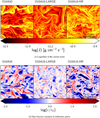 |
Fig. 5 Slices in the x–z plane of the fiducial model O10A10 (left), the large box model O10A10-LARGE (center), and the high-resolution model O10A10-HR (right). All models are displayed at the same size, so we have zoomed out by a factor of two in the case of O10A10-LARGE, which has a box size of 0.1 AU, compared to 0.05 AU for the other two models. |
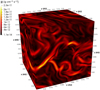 |
Fig. 6 Three-dimensional rendering of the current magnitude for our most resistive model O1A1 (t = 50 Ω−1). |
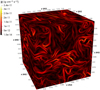 |
Fig. 7 Three-dimensional rendering of the current magnitude for high β model O10A10BETA7500 (t = 80 Ω−1). |
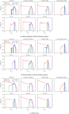 |
Fig. 8 Density PDFs of the three dust sizes and the gas, scaled by the initial values of the density. |
5.2 Implications for chondrule formation
Noticeably, the high density tail of the PDF of millimeter-sized grains, although more extended in the case of the whole box, is relatively similar in all regions, that is to say regardless of whether the current is strong or not. This is interesting if we assume that chondrules do indeed form in flashes (although we recall that many other theories exist). Indeed, a strong dust concentration is a prerequisite for chondrule formation to explain the abundance of volatile elements in chondrules (Alexander et al. 2008). We see in Fig. 8 that it is as likely to happen in regions of strong dissipation as anywhere else in the box. Nevertheless, strong heating events at a high dust concentration (i.e., flashes) involve only a small fraction of the dust mass and of the box volume, as the PDF tail decreases sharply with density. We indeed find that current sheets represent about 1.5% of the box volume in the fiducial case (1.78% in the O10A10-LARGE run and 1.2% in run O10A10-HR) according to the definition of Eq. (14). In all the models, they represent about 1–2% of the total volume. The condition of the rarity of flash occurrences, which is also a prerequisite for a successful chondrule formation theory, is therefore met here. In addition, small grains that are the precursors of the matrix are made from the same material as chondrules; however, they should not experience flashes as often as larger grains in order to survive in the disk, as can be seen from their uniform distribution with a PDF very similar to that of the gas.
We point out that the parameter space for current sheets that could be suitable for chondrule formation is likely to be narrow. For smaller Elsasser numbers (as in the dead zones) than presented here, the MRI is completely damped and therefore no current sheets can form. For larger values, we expect current sheets to form (as they would already form in ideal MHD), but the dissipation rates will also decrease (and eventually become negligible) because they are proportional to the resistivities. Nevertheless, since the inner radii and upper regions of proto-planetary disks are strongly ionized, the Elsasser numbers must always pass through unity at the edge of the dead zone. Arguably, to have a narrow parameter space for strongly dissipative current sheets is in fact convenient to explain chondrule formation since flashes must remain localized events.
5.3 Caveats
We now discuss the various caveats of this study. First of all, as current sheets are very narrow structures, we have to rely on small-scale unstratified simulations in order to attempt resolving them. Although we seem to be reaching convergence for our 2563 model, we noted an effect of the box size on the strength of the turbulence in our fiducial model. In addition, it is not yet clear whether these current sheets would form in a stratified disk. Stratified resistive disks often have low midplane Elsasser numbers that produce disk winds rather than triggering the MRI (Bai & Stone 2013; Lesur et al. 2014), with only very little turbulence in the disk. Some studies (e.g., Gressel et al. 2015) did find current sheets at the edge of the dead zone in their stratified models, although they were not MRI active and were not as resolved as in our models. It is also worth pointing out that a midplane current sheet is also typically reported when disk winds are present (e.g., Bai & Stone 2017). Interestingly, Lesur (2021b) has shown that Ohmic dissipation could push it to the layers of the disk. High resolution studies of stratified disks will need to be computed in order to confirm that current sheet formation does indeed happen systematically at the edge of the dead zone.
The long-term goal of our study is to better understand chondrule formation. Again, stratification could prove to be an important aspect in the matter. The initial conditions that we explored are designed to reproduce the inner regions of proto-planetary disks rather well (at R = 1 AU and z ≈ 1–2H), where chondrule formation in current sheets is expected to happen. As they reproduce conditions above the midplane, the chondrule precursors would need to be lifted efficiently so that they can be reprocessed by these current sheets. Adding stratification in future calculations will allow for it to be assessed whether sufficiently large numbers of millimeter- and 100 micron-sized grains can be lifted high enough to form the observed chondrule population. If the amount of lifted dust material is insufficient, the observed variations of dust fractions might not be enough to generate the high dust concentrations that are also required. Stratification could also give birth to new interesting structures, such as rings (e.g., Béthune et al. 2017), or lead to vertical shear instability if the MRI is completely damped or strongly saturated by ambipolar diffusion (Latter & Kunz 2022). These structures and instabilities would affect the dust dynamics and might be key for the transport of chondrule precursors.
In addition, the models that we have presented here are isothermal for simplicity and because we focus on the dust dynamics. We can still measure the heating rate by Ohmic dissipation and ambipolar diffusion, and we have shown that they are comparable to McNally et al. (2014) who observed a strong temperature variation. However, depending on the cooling rate, which relies on the choice of dust distribution and opacity model, this heating might still be insufficient to form chondrules. This justifies further exploration accounting for the thermal evolution of the disk.
Finally, aside from the B2 dependency of the ambipolar resistivity, we have imposed constant resistivities in our models. This approach is justified because it allows for a simple parameterization of the Ohmic and ambipolar diffusion with the dimensionless Elsasser numbers without requiring any chemical network. However, the downside of the approach is that the dependency of the resistivity with the density and temperature are not taken into account. As was demonstrated by Hubbard et al. (2012), short-circuit instabilities could narrow current sheets significantly, leading to very high temperatures provided that the resistivity decreases with an increasing temperature. Desch & Turner (2015) later argued that these conditions are likely not met with realistic diffusion rates of volatile alkali metals out of dust grains. However, using a constant resistivity, McNally et al. (2014) still reported temperature increases sufficient for chondrule formation in current sheets. The latter instability thus might not be necessary to explain chondrule formation in current sheets. Future high resolution models should assess current sheet formation and evolution with more advanced chemical networks.
5.4 Summary and prospects
In this article, we investigated the dynamics of dust grains with properties similar to chondrules, within unstratified shearing box RAMSES calculations that aim to resolve the formation of dis-sipative current sheets through the nonideal MHD effects of ambipolar diffusion and Ohmic resistivity. We investigated the effect of the strength of the Ohmic resistivity and ambipolar diffusion, the initial density, and magnetic field strength, as well as the numerical resolution and the box size. Our main findings are:
Current sheets form with typical widths of 1–2 × 10⁻³ AU and strong dissipation rates (as in McNally et al. 2014).
Ambipolar diffusion systematically produces dissipation rates more than an order of magnitude higher than those produced by Ohmic resistivity;
These current sheets could produce intermittent, high temperature hot spots in the regions of protoplanetary disks if the cooling rates are not too fast where this effect dominates;
We observe dust fraction variations of up to almost two orders of magnitude for all initial conditions that we studied. These variations are directly connected with current sheet formation, as the dust is typically repelled from the peaks of the current sheets but concentrates in their envelopes;
The regions of strong millimeter-sized grain concentration are highly localized, as required in a successful chondrule formation theory (e.g., Alexander et al. 2008).
All the models described here were computed in the isothermal approximation, so we could not directly derive the temperatures or cooling rates of the hot spots, as would be needed to study chondrule formation. In future work, we plan to include the effect of the ambipolar and Ohmic heating source terms in nonisothermal models. As our initial conditions are optically thick, those models must include radiative transfer. This will be computed in the flux-limited diffusion approximation using the solver of Commerçon et al. (2011) to model diffusion from heated regions. Those models will also include a global cooling at the orbital timescale. They will allow us to assess the formation of hot spots in unstratified shearing box calculations. The inclusion of stratification will allow for the study of current sheet structures that could form even in the absence of MRI, as seen for example in Gressel et al. (2015).
Acknowledgements
We thank the referee for providing useful comments that helped to improve our manuscript. We acknowledge financial support from the Programme National de Physique Stellaire (PNPS) of CNRS/INSU, CEA, and CNES, France. This work was granted access to the HPC resources of CINES (Occigen) and IDRIS (Jean Zay) under the allocation DARIA0080407247 made by GENCI. Computations were also performed at the Common Computing Facility (CCF) of the LABEX Lyon Institute of Origins (ANR-10-LABX-0066). Ugo Lebreuilly acknowledges financial support from the Annette Kade fellowship of the AMNH, from the Ecole Normale Supérieure Paris-Saclay via the Contrats doctoraux spécifiques pour normaliens (CDSN) and from the European Research Council (ERC) via the ERC Synergy Grant ECOGAL (grant 855130). This project was partly supported by the IDEXLyon project (contract no. ANR-16-IDEX-0005) under University of Lyon auspices. The plots were generated using the OSYRIS library developed by Neil Vaytet. We thank Prof. Sébastien Fromang for very useful discussions and comments on our manuscript.
References
- Alexander, C. M. O. D., Grossman, J. N., Ebel, D. S., & Ciesla, F. J. 2008, Science, 320, 1617 [NASA ADS] [CrossRef] [Google Scholar]
- Bai, X.-N., & Stone, J. M. 2011, ApJ, 736, 144 [Google Scholar]
- Bai, X.-N., & Stone, J. M. 2013, ApJ, 769, 76 [Google Scholar]
- Bai, X.-N., & Stone, J. M. 2017, ApJ, 836, 46 [Google Scholar]
- Balbus, S. A., & Hawley, J. F. 1991, ApJ, 376, 214 [Google Scholar]
- Ballabio, G., Dipierro, G., Veronesi, B., et al. 2018, MNRAS, 477, 2766 [NASA ADS] [CrossRef] [Google Scholar]
- Barosch, J., Ebel, D. S., Hezel, D. C., Alpert, S., & Palme, H. 2020, Earth Planet. Sci. Lett., 542, 116286 [CrossRef] [Google Scholar]
- Béthune, W., Lesur, G., & Ferreira, J. 2017, A&A, 600, A75 [NASA ADS] [CrossRef] [EDP Sciences] [Google Scholar]
- Bland, P. A., Alard, O., Benedix, G. K., et al. 2005, PNAS, 102, 13755 [NASA ADS] [CrossRef] [Google Scholar]
- Brandenburg, A., & Zweibel, E. G. 1994, ApJ, 427, L91 [NASA ADS] [CrossRef] [Google Scholar]
- Colling, C., Hennebelle, P., Geen, S., Iffrig, O., & Bournaud, F. 2018, A&A, 620, A21 [NASA ADS] [CrossRef] [EDP Sciences] [Google Scholar]
- Commerçon, B., Teyssier, R., Audit, E., Hennebelle, P., & Chabrier, G. 2011, A&A, 529, A35 [NASA ADS] [CrossRef] [EDP Sciences] [Google Scholar]
- Connolly, H. C. J., & Love, S. G. 1998, Science, 280, 62 [NASA ADS] [CrossRef] [Google Scholar]
- Desch, S. J., & Turner, N. J. 2015, ApJ, 811, 156 [NASA ADS] [CrossRef] [Google Scholar]
- Ebel, D. S., O’Alexander, C. M., & Libourel, G. 2018, Vapor-Melt Exchange. Constraints On Chondrite Formation Conditions And Processes, eds. S. S. Russell, J. Connolly, C. Harold, & A. N. Krot, 151 [Google Scholar]
- Epstein, P. S. 1924, Phys. Rev., 23, 710 [Google Scholar]
- Fleming, T. P., Stone, J. M., & Hawley, J. F. 2000, ApJ, 530, 464 [Google Scholar]
- Friedrich, J. M., Weisberg, M. K., Ebel, D. S., et al. 2015, Chem. Erde/Geochemistry, 75, 419 [NASA ADS] [Google Scholar]
- Fromang, S., Hennebelle, P., & Teyssier, R. 2006, A&A, 457, 371 [NASA ADS] [CrossRef] [EDP Sciences] [Google Scholar]
- Fromang, S., Latter, H., Lesur, G., & Ogilvie, G. I. 2013, A&A, 552, A71 [NASA ADS] [CrossRef] [EDP Sciences] [Google Scholar]
- Gammie, C. F. 1996, ApJ, 457, 355 [Google Scholar]
- Gressel, O., Turner, N. J., Nelson, R. P., & McNally, C. P. 2015, ApJ, 801, 84 [NASA ADS] [CrossRef] [Google Scholar]
- Hawley, J. F., Gammie, C. F., & Balbus, S. A. 1995, ApJ, 440, 742 [Google Scholar]
- Hewins, R. H., & Connolly, H. C. J. 1996, in Chondrules and the Protoplanetary Disk, 197 [Google Scholar]
- Hubbard, A., & Ebel, D. S. 2015, Icarus, 245, 32 [NASA ADS] [CrossRef] [Google Scholar]
- Hubbard, A., McNally, C. P., & Mac Low, M.-M. 2012, ApJ, 761, 58 [NASA ADS] [CrossRef] [Google Scholar]
- Hughes, D.W. 1980, Earth Planet. Sci. Lett., 51, 26 [CrossRef] [Google Scholar]
- Huss, G. R., Alexander, C. M. O., Palme, H., Bland, P. A., & Wasson, J. T. 2005, in Chondrites and the Protoplanetary Disk, eds. A. N. Krot, E. R. D. Scott, & B. Reipurth, Astronomical Society of the Pacific Conference Series, 341, 701 [NASA ADS] [Google Scholar]
- Hutchison, M., Price, D. J., & Laibe, G. 2018, MNRAS, 476, 2186 [Google Scholar]
- Jacquet, E. 2014, Icarus, 232, 176 [NASA ADS] [CrossRef] [Google Scholar]
- Jones, R. H., Grossman, J. N., & Rubin, A. E. 2005, in Chondrites and the Proto- planetary Disk, eds. A. N. Krot, E. R. D. Scott, & B. Reipurth, Astronomical Society of the Pacific Conference Series, 341, 251 [NASA ADS] [Google Scholar]
- Joung, M. K. R., Mac Low, M.-M., & Ebel, D. S. 2004, ApJ, 606, 532 [NASA ADS] [CrossRef] [Google Scholar]
- Laibe, G., & Price, D. J. 2014a, MNRAS, 440, 2136 [Google Scholar]
- Laibe, G., & Price, D. J. 2014b, MNRAS, 440, 2147 [NASA ADS] [CrossRef] [Google Scholar]
- Laibe, G., & Price, D. J. 2014c, MNRAS, 444, 1940 [Google Scholar]
- Latter, H. N., & Kunz, M. W. 2022, MNRAS, 511, 1182 [CrossRef] [Google Scholar]
- Lebreuilly, U., Commerçon, B., & Laibe, G. 2019, A&A, 626, A96 [NASA ADS] [CrossRef] [EDP Sciences] [Google Scholar]
- Lebreuilly, U., Commerçon, B., & Laibe, G. 2020, A&A, 641, A112 [EDP Sciences] [Google Scholar]
- Lesur, G. 2021a, J. Plasma Phys., 87, 205870101 [CrossRef] [Google Scholar]
- Lesur, G. R. J. 2021b, A&A, 650, A35 [NASA ADS] [CrossRef] [EDP Sciences] [Google Scholar]
- Lesur, G., Kunz, M. W., & Fromang, S. 2014, A&A, 566, A56 [NASA ADS] [CrossRef] [EDP Sciences] [Google Scholar]
- Lofgren, G., & Lanier, A. B. 1990, Geochim. Cosmochim. Acta, 54, 3537 [NASA ADS] [CrossRef] [Google Scholar]
- Masson, J., Teyssier, R., Mulet-Marquis, C., Hennebelle, P., & Chabrier, G. 2012, ApJS, 201, 24 [Google Scholar]
- McNally, C. P., Hubbard, A., Yang, C.-C., & Mac Low, M.-M. 2014, ApJ, 791, 62 [NASA ADS] [CrossRef] [Google Scholar]
- Miyoshi, T., & Kusano, K. 2005, J. Comput. Phys., 208, 315 [NASA ADS] [CrossRef] [Google Scholar]
- Palme, H., Hezel, D. C., & Ebel, D. S. 2015, Earth Planet. Sci. Lett., 411, 11 [CrossRef] [Google Scholar]
- Parker, E. N. 1972, ApJ, 174, 499 [NASA ADS] [CrossRef] [Google Scholar]
- Parker, E. N. 1994, Spontaneous current sheets in magnetic fields: with applications to stellar x-rays, International Series in Astronomy and Astrophysics, 1 [Google Scholar]
- Radomsky, P. M., & Hewins, R. H. 1990, Geochim. Cosmochim. Acta, 54, 3475 [NASA ADS] [CrossRef] [Google Scholar]
- Riols, A., & Lesur, G. 2018, A&A, 617, A117 [NASA ADS] [CrossRef] [EDP Sciences] [Google Scholar]
- Riols, A., Lesur, G., & Menard, F. 2020, A&A, 639, A95 [NASA ADS] [CrossRef] [EDP Sciences] [Google Scholar]
- Ross, J., & Latter, H. N. 2018, MNRAS, 477, 3329 [NASA ADS] [CrossRef] [Google Scholar]
- Sano, T., Miyama, S. M., Umebayashi, T., & Nakano, T. 2000, ApJ, 543, 486 [NASA ADS] [CrossRef] [Google Scholar]
- Shakura, N. I., & Sunyaev, R. A. 1976, MNRAS, 175, 613 [NASA ADS] [CrossRef] [Google Scholar]
- Stone, J. M., Hawley, J. F., Gammie, C. F., & Balbus, S. A. 1996, ApJ, 463, 656 [NASA ADS] [CrossRef] [Google Scholar]
- Suresh, A. 2000, SIAM J. Sci. Comput., 22, 1184 [NASA ADS] [CrossRef] [Google Scholar]
- Teyssier, R. 2002, A&A, 385, 337 [CrossRef] [EDP Sciences] [Google Scholar]
- Wardle, M. 1999, MNRAS, 307, 849 [NASA ADS] [CrossRef] [Google Scholar]
For simplicity we write Ω ≡ Ωkep(R0).
Or Els when the source of nonideal MHD is not specified.
All Tables
All Figures
|
Fig. 1 Three-dimensional rendering of the current magnitude for our fiducial model O10A10 (t = 50 Ω−1). |
| In the text | |
|
Fig. 2 Edge-on slices of the relative dust fraction variations for O10A10 (fiducial run), O1A1, O10A1 and O1A10 (more resistive runs), from left to right. The slices are displayed at t ~ 8 yr (~50 Ω−1), except for run O 10A10BETA7500 for which they are displayed at t ~ 32 yr (~200 Ω−1). The dust grain size increases from top to bottom. |
| In the text | |
|
Fig. 3 Cartoon illustrating the decoupling of the gas and dust near a current sheet. Left: schematic local view of a current sheet and the dust drift velocity in its vicinity; B is the magnetic field, J is the electric current and wk is the dust drift velocity. Right: dust ratio variation near a current sheet (zoom in and 90 degree rotation of the left snapshot of Fig. 5; the color scale is the same, with red high and blue low). The dotted line shows the approximate (hand drown) position of the current sheet, the white arrow represent the drift velocity (green) and J × B (black) direction projected in the plane of the slice. |
| In the text | |
|
Fig. 4 Histogram of the dust fraction e as a function of the ambipolar and Ohmic heating source terms for the 10 µm (left), 100 µm (middle) and 1 mm grains (right) for the O10A10 model at t = 50 Ω−1. The colors represent the integrated total mass (the color bar is log-scaled). We note that the heating is dominated by ambipolar diffusion for all grain sizes. |
| In the text | |
|
Fig. 5 Slices in the x–z plane of the fiducial model O10A10 (left), the large box model O10A10-LARGE (center), and the high-resolution model O10A10-HR (right). All models are displayed at the same size, so we have zoomed out by a factor of two in the case of O10A10-LARGE, which has a box size of 0.1 AU, compared to 0.05 AU for the other two models. |
| In the text | |
|
Fig. 6 Three-dimensional rendering of the current magnitude for our most resistive model O1A1 (t = 50 Ω−1). |
| In the text | |
|
Fig. 7 Three-dimensional rendering of the current magnitude for high β model O10A10BETA7500 (t = 80 Ω−1). |
| In the text | |
|
Fig. 8 Density PDFs of the three dust sizes and the gas, scaled by the initial values of the density. |
| In the text | |
Current usage metrics show cumulative count of Article Views (full-text article views including HTML views, PDF and ePub downloads, according to the available data) and Abstracts Views on Vision4Press platform.
Data correspond to usage on the plateform after 2015. The current usage metrics is available 48-96 hours after online publication and is updated daily on week days.
Initial download of the metrics may take a while.