Fig. C.1.
Download original image
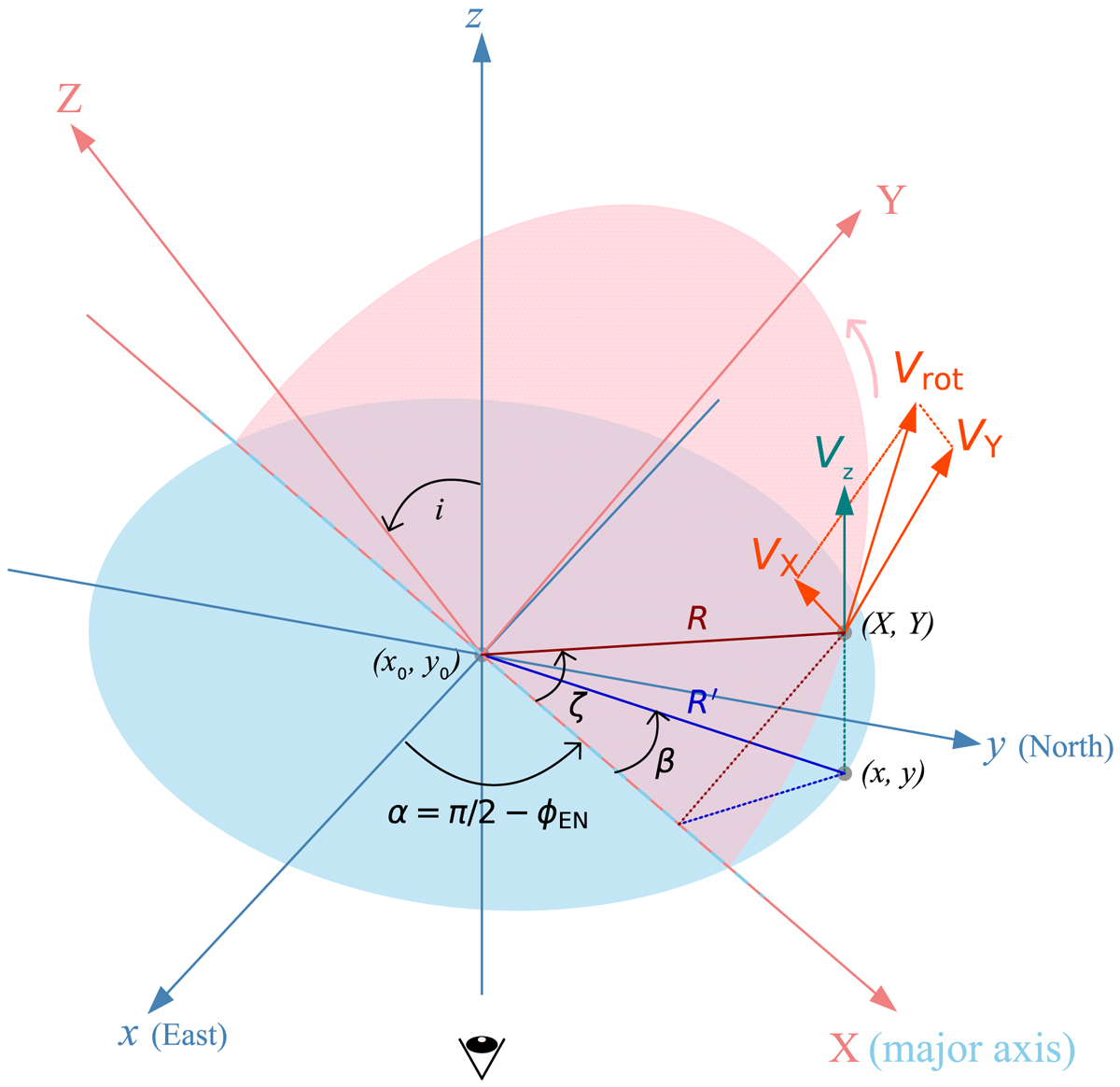
Simple schematic diagram for the tilted ring model. The pink semiellipse represents the galaxy plane with a coordinate system of XYZ. The red-based color lines are on or perpendicular to the galaxy plane. The light-blue ellipse presents the sky plane with a coordinate system of xyz. The blue color lines are on or perpendicular to the sky plane. We takes the x direction as the east and the y direction as the north. The major axis on the sky plane coincides with the X axis on the galaxy plane. The line-of-sight direction is along the z direction from the bottom to the top. The galaxy plane is inclined with an angle of i (the inclination angle, i.e., the angle between the line of sight and the perpendicular line to the galaxy plane XY). The data point (X, Y) with a distance of R to the center rotates counterclockwise with a rotation velocity of Vrot on the galaxy plane. What we can see is the line-of-sight component Vz of the rotation velocity Vrot. The angle between the major axis on the sky plane and the line connecting the galaxy center (x0, y0) and the data point (X, Y) is the azimuth angle ζ. The position angle ϕ is defined as the angle counting from the north (y axis) to the major axis of the receding half on the galaxy plane. After tilting, the data point (X, Y), the distance R and the azimuth angle ζ on the galaxy plane project to (x, y), R′ and β on the sky plane.
Current usage metrics show cumulative count of Article Views (full-text article views including HTML views, PDF and ePub downloads, according to the available data) and Abstracts Views on Vision4Press platform.
Data correspond to usage on the plateform after 2015. The current usage metrics is available 48-96 hours after online publication and is updated daily on week days.
Initial download of the metrics may take a while.