Fig. 4
Download original image
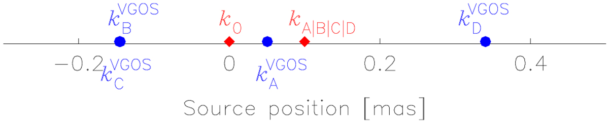
One-dimensional diagram of the relation between the VGOS group delay positions (blue dots) and the locations of the radio emission in individual bands (red rhombuses). Four scenarios are shown: the location of the radio emission in band A, B, C, or D as marked by kA|B|C|D is offset by 0.1 mas with respect to the locations in the other three bands, which are located at the origin marked by k0. The VGOS group delay positions are shown as blue dots: for example, ![]() is where the VGOS group delay position is located when the location of the radio emission in band D is offset by 0.1 mas with respect to the other three bands.
is where the VGOS group delay position is located when the location of the radio emission in band D is offset by 0.1 mas with respect to the other three bands.
Current usage metrics show cumulative count of Article Views (full-text article views including HTML views, PDF and ePub downloads, according to the available data) and Abstracts Views on Vision4Press platform.
Data correspond to usage on the plateform after 2015. The current usage metrics is available 48-96 hours after online publication and is updated daily on week days.
Initial download of the metrics may take a while.