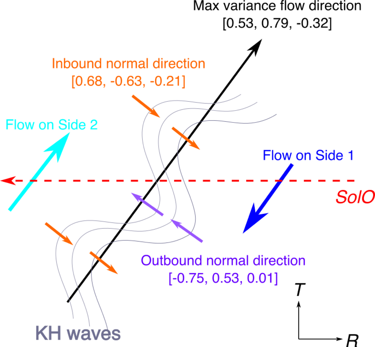
Fig. 9.
Download original image
Schematic sketch of the KH waves based on the average normal directions of the inbound and outbound crossings and the shear flow direction (maximum variance direction of V) in the R − T plane. The flow directions on Side 1 and Side 2 correspond to the velocity perturbation vectors outside the wave-like interval in Fig. 8f. The shear flow direction is nearly perpendicular to the wave edge normals, which can be interpreted as wavy structures developed within the velocity shear layer consistent with KH waves.
Current usage metrics show cumulative count of Article Views (full-text article views including HTML views, PDF and ePub downloads, according to the available data) and Abstracts Views on Vision4Press platform.
Data correspond to usage on the plateform after 2015. The current usage metrics is available 48-96 hours after online publication and is updated daily on week days.
Initial download of the metrics may take a while.