Fig. 5.
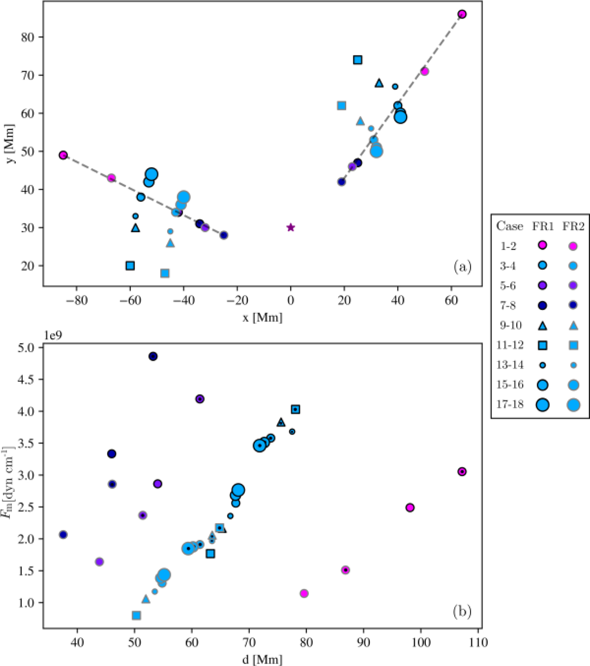
(a) Null-point locations at t = 0 s for all cases. The purple star represents the position of the FR, black edges correspond to FR1 simulations, and grey edges to FR2 ones. Dashed lines indicate the location of null points for aligned (left) and anti-aligned (right) cases, with the CH at the same distance D and same parameter W. The symbol colour changes with the strength B0 of the magnetic field (from weaker to stronger: pink, light blue, blue violet, and dark blue), the size changes with the parameter W (bigger means wider), and the shape changes with the distance D (from closer to farther: circle, triangle and square). (b) Module of the magnetic force per unit length versus null-point distance to the FR centre. Symbols have the same meanings as in (a). A black dot in the symbol centre indicates an anti-aligned case.
Current usage metrics show cumulative count of Article Views (full-text article views including HTML views, PDF and ePub downloads, according to the available data) and Abstracts Views on Vision4Press platform.
Data correspond to usage on the plateform after 2015. The current usage metrics is available 48-96 hours after online publication and is updated daily on week days.
Initial download of the metrics may take a while.