Fig. C.1.
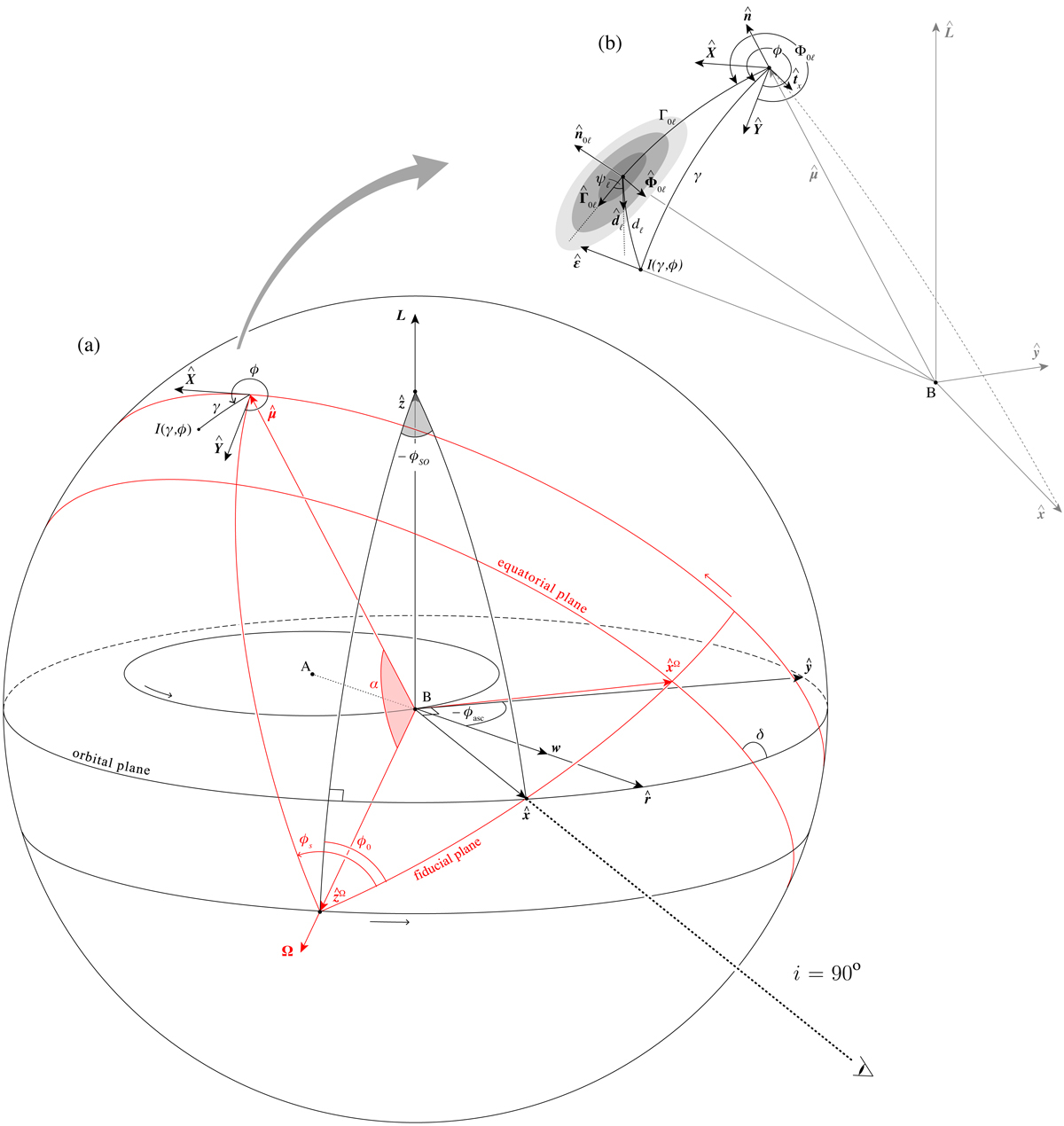
(a) Geometry of the model used in this work to describe the effect of the radial wind of pulsar A (w) on the emission of pulsar B. In this figure, Ω and ![]() are the spin and magnetic moment of pulsar B, respectively, and L is the orbital angular momentum of the binary system. For clarity, we separated the elements corresponding to the frame of the orbit (
are the spin and magnetic moment of pulsar B, respectively, and L is the orbital angular momentum of the binary system. For clarity, we separated the elements corresponding to the frame of the orbit (![]() ) and those corresponding to the frame of the pulsar (
) and those corresponding to the frame of the pulsar (![]() ) in black and red, respectively. The sense of pulsar B’s orbit around pulsar A and that of μ about Ω are shown with black and red arrows, respectively. Also shown with a black arrow is the sense of the geodetic precession of Ω about L (defined by an increasing ϕSO). We note that, compared to Breton et al. (2008), we used the opposite direction for L. The direction to the observer coincides with the unit vector
) in black and red, respectively. The sense of pulsar B’s orbit around pulsar A and that of μ about Ω are shown with black and red arrows, respectively. Also shown with a black arrow is the sense of the geodetic precession of Ω about L (defined by an increasing ϕSO). We note that, compared to Breton et al. (2008), we used the opposite direction for L. The direction to the observer coincides with the unit vector ![]() . In this work, we have assumed that the double pulsar system is viewed exactly edge-on: so, the orbital inclination, i, is exactly equal to 90°. At the position of
. In this work, we have assumed that the double pulsar system is viewed exactly edge-on: so, the orbital inclination, i, is exactly equal to 90°. At the position of ![]() , we show an example location in the beam, with beam coordinates (γ, ϕ), corresponding to intensity I(γ, ϕ) (see Eq. (10)). For the definition of the reference frames and angles shown, the reader is directed to Sect. 4.2. (b) The definitions of the angles that are used in our parametrisation of pulsar B’s emission beam location and intensity.
, we show an example location in the beam, with beam coordinates (γ, ϕ), corresponding to intensity I(γ, ϕ) (see Eq. (10)). For the definition of the reference frames and angles shown, the reader is directed to Sect. 4.2. (b) The definitions of the angles that are used in our parametrisation of pulsar B’s emission beam location and intensity.
Current usage metrics show cumulative count of Article Views (full-text article views including HTML views, PDF and ePub downloads, according to the available data) and Abstracts Views on Vision4Press platform.
Data correspond to usage on the plateform after 2015. The current usage metrics is available 48-96 hours after online publication and is updated daily on week days.
Initial download of the metrics may take a while.