Fig. 1
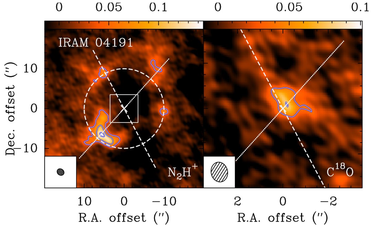
Left panel: N2H+ (1–0) emission integrated over all seven hyperfine components. Contours show the emission in steps of 3σ, starting at 3σ, with σ = 15 mJy beam−1 km s−1. The filled ellipse in the lower left corner of the large panel indicates the synthesized beam size of the N2H+ observationsat 3 mm, while the FWHM primary beam is 52″ at 93 GHz. The dashed white line illustrates the outflow direction (PA = 28°, Belloche et al. 2002), and the white cross shows the position of the continuum source as determined in Maury et al. (2019; see their Fig. B.6). The dotted line shows the direction of the cuts through the N2H+ emission maximum shown in Fig. 2. The dashed circle marks a radius of 10″, which was stated as being the N2H+ hole rim radius by Belloche & André (2004) and Lee et al. (2005). Right panel: zoom into the inner ±2″ in integrated C18O emission. Contours are in steps of 3σ, starting at 3σ, with σ = 13 mJy beam−1 km s−1. The corresponding synthesized beam size at 1.4 mm is displayed in the lower left corner, while the FWHM primary beam is 22″ at 220 GHz. The white lines are the same as in the left panel.
Current usage metrics show cumulative count of Article Views (full-text article views including HTML views, PDF and ePub downloads, according to the available data) and Abstracts Views on Vision4Press platform.
Data correspond to usage on the plateform after 2015. The current usage metrics is available 48-96 hours after online publication and is updated daily on week days.
Initial download of the metrics may take a while.