Fig. 7
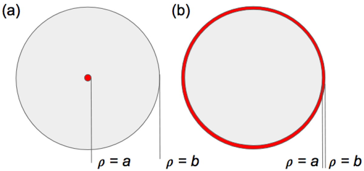
Geometry of the concentric disk model for modelling of solar panels with biased elements as described in Sect. 5.1 for two different applications. Panel a: single exposed biased conductor on the main area of the solar panel (Sect. 5.2); panel b: exposes biased conductors along the edge (Sect. 5.3). Grey areas represent the main solar panel at spacecraft potential, red a biased element.
Current usage metrics show cumulative count of Article Views (full-text article views including HTML views, PDF and ePub downloads, according to the available data) and Abstracts Views on Vision4Press platform.
Data correspond to usage on the plateform after 2015. The current usage metrics is available 48-96 hours after online publication and is updated daily on week days.
Initial download of the metrics may take a while.