Fig. 2.
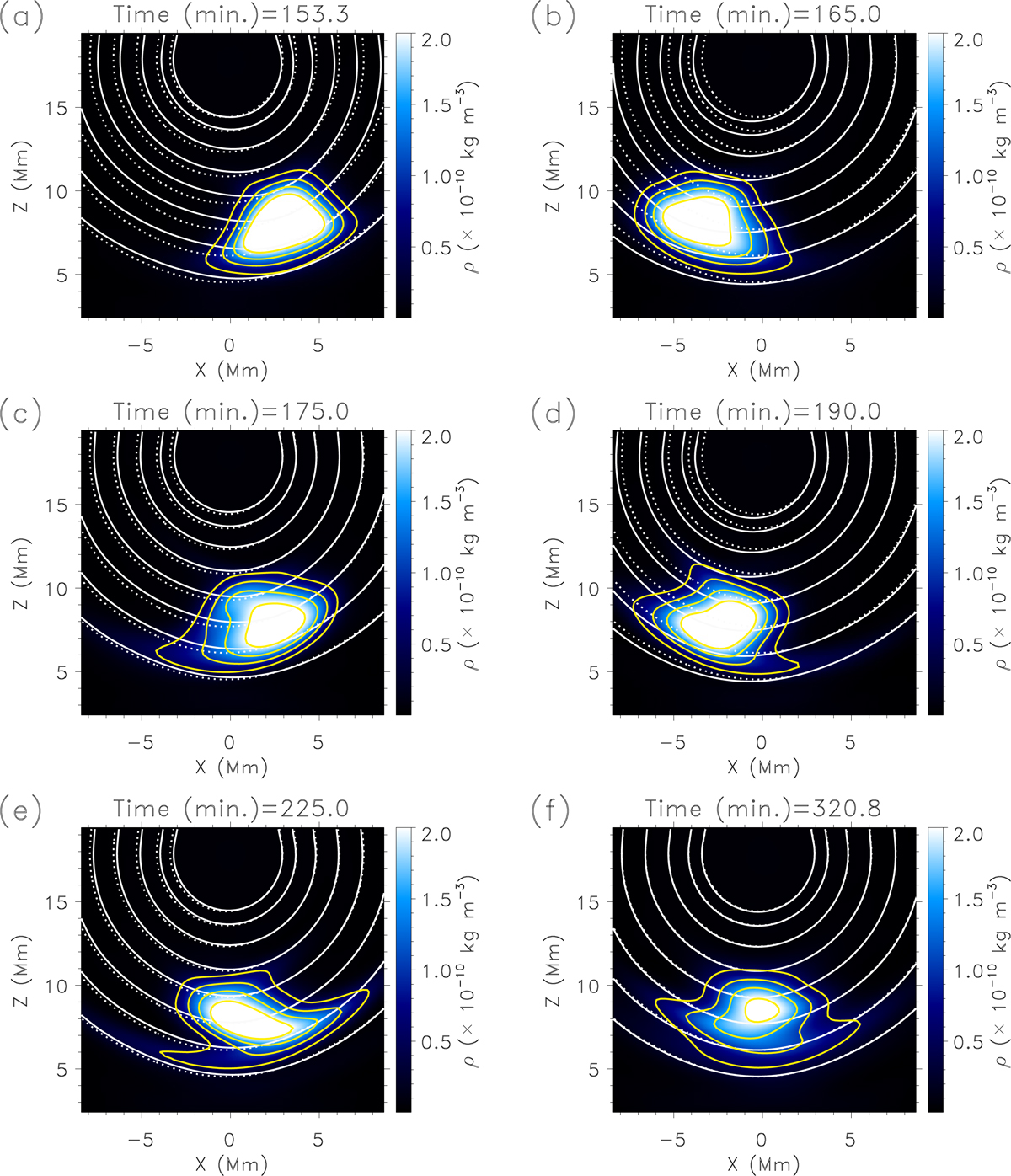
Evolution of the density and magnetic field after the horizontal perturbation. The figure shows the dipped part of the flux rope. Panel a demonstrates the motion of the prominence just after the perturbation; panels b, c: lagging of the bottom part from the rest of the prominence body, and panels d, e demonstrate the zigzag shape of the motions. Panel f: state of the prominence in the final stage of simulation. The dashed lines indicate the magnetic field lines before the perturbation. The yellow lines represent the density isocontours.
Current usage metrics show cumulative count of Article Views (full-text article views including HTML views, PDF and ePub downloads, according to the available data) and Abstracts Views on Vision4Press platform.
Data correspond to usage on the plateform after 2015. The current usage metrics is available 48-96 hours after online publication and is updated daily on week days.
Initial download of the metrics may take a while.