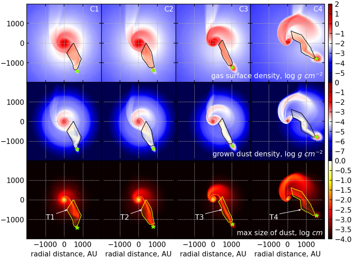
Fig. 7

Spatial distribution of gas surface density (top row), grown dust surface density (middle row), and maximal dust grain size (bottom row) shown for four models: C1 (first column), C2 (second column), C3 (third column) and C4 (fourth column). Tails are shown at 10.3 kyr after the launch of the intruder. The post-collisional tail structures are marked with the black and yellow contour lines. The star symbols indicate the position of the intruder. The gas and dust surface densities are in log g cm−2, the maximum dust size is in log cm.
Current usage metrics show cumulative count of Article Views (full-text article views including HTML views, PDF and ePub downloads, according to the available data) and Abstracts Views on Vision4Press platform.
Data correspond to usage on the plateform after 2015. The current usage metrics is available 48-96 hours after online publication and is updated daily on week days.
Initial download of the metrics may take a while.


