Fig. 21.
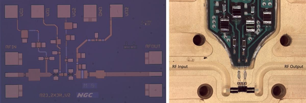
Left: microscope photograph of one of the fabricated UoM MMICs. The die size of the UoM MMICs is 1.3 mm × 0.9 mm. Right: interior of the packaging showing the MMIC, the waveguide to microstrip transitions, WR10 waveguide channels (with the RF input on the left and output on the right), and the off-chip bias protection circuit. The MMIC die can be seen in the lower middle portion of the photo, below the bias protection circuit. This figure is based on figures presented in Cuadrado-Calle et al. (2017a).
Current usage metrics show cumulative count of Article Views (full-text article views including HTML views, PDF and ePub downloads, according to the available data) and Abstracts Views on Vision4Press platform.
Data correspond to usage on the plateform after 2015. The current usage metrics is available 48-96 hours after online publication and is updated daily on week days.
Initial download of the metrics may take a while.