Fig. 1.
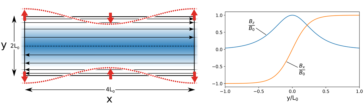
Left panel: diagram representing the initial conditions. The domain is periodic in the x-direction, with rigid boundaries in the y-direction after the perturbation is applied. The guide field Bz (out of the plane) is shown in blue, overlaid with field lines showing the x-component of the magnetic field Bx. The red dotted line shows the form of the perturbation applied at the boundary: a sinusoidal inflow and outflow pattern with red arrows indicating direction, equal and opposite at the upper and lower y boundaries for a short period of time (see Eq. (9)). Right panel: the initial force free magnetic field components.
Current usage metrics show cumulative count of Article Views (full-text article views including HTML views, PDF and ePub downloads, according to the available data) and Abstracts Views on Vision4Press platform.
Data correspond to usage on the plateform after 2015. The current usage metrics is available 48-96 hours after online publication and is updated daily on week days.
Initial download of the metrics may take a while.