| Issue |
A&A
Volume 617, September 2018
|
|
|---|---|---|
| Article Number | A50 | |
| Number of page(s) | 10 | |
| Section | The Sun | |
| DOI | https://doi.org/10.1051/0004-6361/201732494 | |
| Published online | 18 September 2018 | |
Investigating 4D coronal heating events in magnetohydrodynamic simulations
1 Rosseland Centre for Solar Physics, University of Oslo, PO Box 1029 Blindern, 0315 Oslo, Norway
2 Institute of Theoretical Astrophysics, University of Oslo, PO Box 1029 Blindern, 0315 Oslo, Norway
e-mail: This email address is being protected from spambots. You need JavaScript enabled to view it.
Received:
19
December
2017
Accepted:
1
July
2018
Abstract
Context. One candidate model for heating the solar corona is magnetic reconnection that embodies Ohmic dissipation of current sheets. When numerous small-scale magnetic reconnection events occur, then it is possible to heat the corona; if ever observed, these events would have been the speculated nanoflares.
Aims. Because of the limitations of current instrumentation, nanoflares cannot be resolved. But their importance is evaluated via statistics by finding the power-law index of energy distribution. This method is however biased for technical and physical reasons. We aim to overcome limitations imposed by observations and statistical analysis. This way, we identify, and study these small-scale impulsive events.
Methods. We employed a three-dimensional magnetohydrodynamic (3D MHD) simulation using the Bifrost code. We also employed a new technique to identify the evolution of 3D joule heating events in the corona. Then, we derived parameters describing the heating events in these locations, studied their geometrical properties and where they occurred with respect to the magnetic field.
Results. We report on the identification of heating events. We obtain the distribution of duration, released energy, and volume. We also find weak power-law correlation between these parameters. In addition, we extract information about geometrical parameters of 2D slices of 3D events, and about the evolution of resolved joule heating compared to the total joule heating and magnetic energy in the corona. Furthermore, we identify relations between the location of heating events and the magnetic field.
Conclusions. Even though the energy power index is less than 2, when classifying the energy release into three categories with respect to the energy release (pico-, nano-, and micro-events), we find that nano-events release 82% of the resolved energy. This percentage corresponds to an energy flux larger than that needed to heat the corona. Although no direct conclusions can be drawn, it seems that the most popular population among small-scale events is the one that contains nano-scale energetic events that are short lived with small spatial extend. Generally, the locations and size of heating events are affected by the magnitude of the magnetic field.
Key words: magnetohydrodynamics: / Sun: corona / Sun: flares / methods: statistical
© ESO 2018
1. Introduction
The mechanical energy contained in the flows of the convective zone and the photosphere is so big that only a fraction is needed to heat the solar corona (Gesztelyi et al. 1986). It is conventional to attribute the medium of transferring the energy generated by the mechanical drivers to the magnetic field. Other mechanisms have been proven not to work. For instance, energy cannot be transported from the photosphere to the corona via mass convection, nor via sound waves because this class of waves is dissipated or reflected before reaching the corona (Carlsson & Stein 2002; Carlsson et al. 2007). Small velocity amplitude magnetohydrodynamic (MHD) waves can reach the corona, but those do not carry enough energy (Hara & Ichimoto 1999; Tomczyk et al. 2007). The only waves that can penetrate into the region and transport enough energy are Alfvén waves, however dissipating these waves is not so easy (van Ballegooijen et al. 2011; Asgari-Targhi & van Ballegooijen 2012).
The magnetic field, anchored in the photosphere, extends throughout the solar atmosphere, establishing a link between the photosphere and corona. This link enables mechanical energy to propagate towards the corona via the Poynting flux (Klimchuk 2006; Hansteen et al. 2015). There are two components of the vertical Poynting flux: the horizontal motions of the vertical component of magnetic field and the transport of the horizontal field by vertical motions. Both of these components transport energy into the corona.
The energy carried by the Poynting flux is stored in the form of currents. The process involves injection of energy that transforms a potential into a non-potential field. As a consequence, magnetic field gradients appear that are responsible for current sheet formation. Current sheets store any excess energy above the energy level of a potential field (Galsgaard & Nordlund 1996; Gudiksen & Nordlund 2005). In MHD, current sheets express the magnetic field gradients, i.e. J ∝ ∇ × B. However, the magnetic field cannot store infinite energy. At some point, a critical value is reached and energy is released impulsively in a stochastic manner. The maximum amount of energy that can be released is the non-potential magnetic energy, which is replaced continually owing to the motions of the mechanical drivers in the photosphere and convective zone. As shown by Hansteen et al. (2015), the total energy input in the coronal region is “spatially intermittent and temporally episodic”, but in the long-term heating is almost constant.
The inclination between currents in current sheets and a magnetic field plays an important role in the work done. When a current is aligned with the magnetic field, then the exerted Lorentz force on the plasma is zero, i.e. J × B = 0. However, when there is an inclination between current and magnetic field, the Lorentz force is then non-zero and work is done. Then, energy stored in the currents in the presence of finite resistivity is dissipated, and cross-field currents release a part of the stored energy via joule heating (Low 1990). If currents (and thus electric fields) are perpendicular to the magnetic field, then the magnetic field topology changes significantly and magnetic reconnection occurs (Parker 1972).
The non-potential magnetic field can be mapped through quasi-separatrix layers (QSL; Aulanier et al. 2006; QSLs are the equivalent to separatrices in 2D. While the stressing of the magnetic field continues and currents form, QSLs become thinner and magnetic field gradients larger until reconnection takes place (Aulanier et al. 2006). The high current density, helps to increase the resistivity locally and allows the magnetic flux of opposite polarity to reconnect. During magnetic reconnection several processes take place, such as direct thermal heating via joule heating, energy transport via acceleration of particles, excitation of waves, and shock generation.
Current sheets have scales that vary in a hierarchical manner from bigger to smaller scales. Current sheets can reach scales so small that magnetic energy dissipation via joule or viscous heating is feasible. Fragmentation of current sheets occurs mostly in regions with very large resistivity. The fragmentation stops when currents have scales, where resistive diffusion (Nordlund & Galsgaard 2012) or friction can act (van Ballegooijen 1986). Currents evolve on similar timescales as the magnetic field does. According to Galsgaard & Nordlund (1996), current sheet formation takes a few seconds, while current sheet dissipation can take from few to thousands of seconds.
The observational traces of magnetic reconnection are flares. Flares range in energy output from large (1032 erg) to the smallest postulated but so far unobserved nanoflares (1024 erg), spanning many orders of magnitude.
Statistics of flares are important because nanoflares, according to Parker (1972, 1988), can heat the solar corona if a very large number occur. According to observations, the frequency of energy release from flaring events is distributed as a power-law function N(E) ∝ EαE, where αE is the power index of energy, and N(E) the number of events in the energy range E, and E + δE. If the index is larger than two, then nanoflares are more important energetically than large flares (Hudson 1991). Constraining the value of the power-law index has been the goal of numerous observational campaigns and investigations, but the value of the power-law index is still disputed. Examples of such observations are the following: in peak of hard X-rays (HXR), Christe et al. (2008) found 1.58 ± 0.02; in the fluence of HXR, Pérez Enriquez & Miroshnichenko (1999) and Crosby et al. (1993) found 1.39 ± 0.01, and 1.48 ± 0.02 respectively; in the fluence of soft X-rays (SXR) and peak of SXR, Drake (1971) found 1.44 and 1.75, respectively; in the peak of ultraviolet (UV) and extreme-ultraviolet (EUV) intensities, Aschwanden & Parnell (2002) found 1.71 ± 0.1 in 171 Å, 1.75 ± 0.07 in 191 Å, and 1.52 ± 0.1 in aluminium-magnesium filter on the Yohkoh spacecraft. Since very small events cannot be resolved by the current instrumentation and the observed power-law indices are smaller than two, taking the raw numbers from these works indicates that the power-law index is less than two, suggesting that large flaring events are more significant energetically than smaller flaring events.
Other quantities that describe heating events also follow power laws. For example, the duration of each event exhibits a power-law slope in observations that depends on the solar cycle. The slope has minimum value during the solar minimum and maximum during solar maximum. In fact, Aschwanden & Freeland (2012) found in 35 years of GOES observations that during solar minimum the slope is as small as 2, while during solar maxima the slope ranges from 2 to 5. In the literature, the volumes of flares are usually calculated by making strict assumptions, making them less reliable, but producing a power-law distribution with power-law indices that vary between 1.5 and 2.08 (examples are in Table 9 in Aschwanden et al. 2016).
However, finding the power-law index for flare distributions is not trivial owing to observational biases. Finding the volume of a flare is difficult because of our inherently 2D observations. Both background and foreground contamination makes the estimation of the distance taken up by the flare along the line of sight very difficult. The determination of thermal energies requires the knowledge of the volume occupied by the flaring events (Benz & Krucker 2002). We are only able to deduce information from observations about the area perpendicular to the line of sight, and therefore scaling laws depend on assumptions to calculate the volume (e.g. Benz & Krucker 2002; Aschwanden & Shimizu 2013). There is no direct connection between the dimension of a flare in each of the three spatial dimensions, so we cannot find the volume of a flare from two measured dimensions (Morales & Charbonneau 2009). The passband used for the observations also produces different projected areas since they are sensitive to gas at different temperatures and the densities at the different temperatures are rarely equal. Finding the duration of flares is not trivial because flare identification algorithms depend on the identification technique and criteria used therein. These problems create uncertainties in the estimated parameters of the flares.
Sampling or selection bias is another problem that is rarely taken into account. Typically, the method used to detect and select flaring events produces these biases. The synchronicity of observations from different passbands has different effects on small and large flares. Short events are affected by the integration time, either because the events are drowned out by background (if the integration time is long) or under sampled (if the time between exposures are long). Resolution also under-represents low energy events, because small events produce smaller peaks if they have subpixel sizes. Larger flares can be subject to biases if the total observation time is too short. Finally, distributions can be skewed if a large number of small unresolved events are labelled as a single large event. The fitting method, the error bars used in fitting, and the correct choice of background heating and noise subtraction affect the power-law index (Benz & Krucker 2002). As stated also by Hannah et al. (2011), the large range of power-law slopes found in different studies from various researchers is also a product of the method used to extract results and the instrumentation employed in different periods during the solar cycle.
In this study, our most important goal is to study 3D heating events related to magnetic reconnection and evaluate their contribution towards heating the corona. This must happen in an experiment that overcomes most of the observational restrictions. To achieve this, we simulate the solar atmosphere using the Bifrost code (Gudiksen et al. 2011), use a relatively new method to identify 3D heating events, and follow their evolution in time.
Being able to identify 3D events gives us the opportunity to study them in detail. More specifically, we want to check to what extend small-scale events contribute to coronal heating, and to identify if there is a lower energy cut-off. In addition, we want to assess the contribution of joule heating events with respect to the total joule heating and magnetic energy in the corona. We also want to explore how heating events manifest themselves in 3D space, and check their evolution in time. Another objective of this study is to check if we can identify any scaling laws between energy, duration, and volume that could help observers to derive conclusions by observing one parameter instead of another. Moreover, we want to locate where heating events occur with respect to the magnetic field and compare the results with the literature.
This paper discusses the properties of heating events related to magnetic reconnections that have been identified in a 3D simulation. We study their individual and collective behaviours under the prism of coronal heating. The remainder of this paper is organised in the following way: In Sect. 2.1, we briefly describe the Bifrost code (Gudiksen et al. 2011); in Sect. 2.2, we describe the method used to identify the evolution of joule heating events, and the rest of the parameters. Section 3 reports on the findings. More specifically, Sect. 3.1 includes the results of our investigation on the geometrical properties of the 3D structures we identify, while Sect. 3.2 contains the distributions and power-law fits of duration, energy, and mean volume together with the cumulative distribution function (CDF) of the last quantity. We perform a statistical analysis of several parameters in Sect. 4. Finally, in Sect. 5, we discuss our findings and derive conclusions.
2. Method
In the current section, we briefly describe the Bifrost code used to create the snapshots of the solar atmosphere we will be analysing in this work. We also describe the method employed to detect heating events spatially and temporally in the region of interest (ROI).
2.1. Bifrost simulation
The Bifrost code (Gudiksen & Nordlund 2005; Gudiksen et al. 2011) is a 3D MHD code that can simulate a stellar atmosphere from the convective zone up to the corona. It can include numerous special physics and boundary conditions to model stellar atmospheres adequately. This code solves a closed set of MHD partial differential equations along with equations describing radiation transport, thermal conduction along the magnetic field, and a realistic equation of state. A Cartesian grid is used to solve the system of equations using sixth order differential operators, fifth order interpolation operators, and a third order Hyman method with variable time step. The description of the non-grey radiative transfer includes the scattering between optically thin and thick regions of the photosphere and chromosphere to model the region properly (Hayek et al. 2010), and a chromospheric radiation approximation where the energy balance is critically dependent on the scattering in strong spectral lines and optically thin radiation in the upper atmosphere.
The energy equation used in Bifrost is of special interest in this work. The radiative and conductive processes can be described through the following equation of the evolution of the internal energy:
 (1)
where e is the internal energy per unit volume, u the velocity vector, P the gas pressure, and QC the contribution from the Spitzer thermal conduction along the magnetic field (Spitzer 1962). The parameter QJ represents the joule heating, QVi is viscous heating, and QR energy contribution from the emitted or absorbed radiation.
(1)
where e is the internal energy per unit volume, u the velocity vector, P the gas pressure, and QC the contribution from the Spitzer thermal conduction along the magnetic field (Spitzer 1962). The parameter QJ represents the joule heating, QVi is viscous heating, and QR energy contribution from the emitted or absorbed radiation.
In this paper, we also employ the simulation used by Kanella & Gudiksen (2017). We use the data from a simulation that includes a region enclosed between the solar convective zone and the corona. The simulated convective zone extends 2.5 Mm below the photosphere and the simulated box reaches 14.3 Mm above the photosphere. In the vertical direction z, the upper boundary is open, while the lower boundary maintains the convective flow by giving the inflowing gas enough entropy to maintain the correct effective temperature of the solar photosphere, i.e. 5780 K. In the horizontal x-y plane, the numerical volume is periodic.
The simulation box contains 768 × 768 × 768 cells and spans a physical volume of 24 × 24 × 16.8 Mm3. The horizontal grid spacing (dx = dy) is constant and equal to 31.25 km, while the vertical grid spacing varies to resolve the magnetic field, temperature, and pressure scale heights. The vertical spacing (dz) is roughly 26 km in the photosphere and chromosphere and increases slowly up to 165 km at the upper boundary. This simulation was created to resemble a structure of magnetic field network embedded in the quiet Sun (QS). The configuration contains two relatively strong magnetic regions of opposite polarity, which are connected with a magnetic structure that has a loop-like shape. Throughout the simulation a horizontal field of 100 gauss is injected in the inflowing regions at the lower boundary. This injection maintains the well-known salt and pepper magnetic field. A more detailed description of the simulation set-up can be found in Carlsson et al. (2016); the only difference is that the set-up described in Carlsson et al. (2016) also incorporates the effects of non-equilibrium ionisation of hydrogen.
For our analysis, we chose a ROI that corresponds to the corona. The ROI starts at a height of 3.28 Mm above the photosphere, where the temperature is equal to 1 MK, and extends up to the top of the simulation box excluding a few cells zones because they are affected by boundary conditions. Therefore, the volume of interest is 24 × 24 × 9.5 Mm3 and corresponds to 768 × 768 × 331 grid cells.
2.2. Identification method
To study the effects of magnetic reconnection quantitatively, we choose to analyse the joule heating term in Eq. (1). The grid size is of the order of a few decades of kilometres and represents scales that are much larger than the physical scales at which physical resistivity and viscosity are effective. Therefore, Bifrost uses the minimum numerical diffusivity (resistivity), which ensures the stability of the code. Further details about the numerical resistivity and the heating term can be found in our previous work (Kanella & Gudiksen 2017) and in Gudiksen et al. (2011).
In our previous work (Kanella & Gudiksen 2017) we described the details of the numerical tool, i.e. ImageJ (Collins 2007; Ollion et al. 2013), and algorithm used to identify 3D structures in each snapshot, i.e. Adaptive Generic Iterative Thresholding Algorithm (AGITA; Ollion et al. 2013; Gul-Mohammed et al. 2014). In the following, we describe the identification method and the quantity used for this purpose in different terms so as to understand the underlying process.
Magnetic reconnection is a topological phenomenon, therefore the identification of each event is difficult without a detailed study of each region, however the implicit effect of reconnection can be located. The best proxy we have to study such topological events is to investigate the joule heating term in the Bifrost code. Joule heating depends, among other parameters, on current density, which in MHD expresses the degree of magnetic field gradients. When there is inclination between the magnetic field and currents, then work is done, and it is a requirement that part of the current is perpendicular to the magnetic field in order for the magnetic field to reconnect.
The method we employ in this work and in Kanella & Gudiksen (2017) depends on the ability of the algorithm to find spikes (local maxima) in the joule heating in 3D space, and follows the negative gradient in all directions with a constant pre-specified step. The process is performed for various thresholds (specified by the pre-specified step), each time with a lower boundary in joule heating at E0. The process is repeated until the gradient at some level of the heating becomes a very small fraction of the local maximum that has volume that does not overlap with other identified structures. The 3D iso-surface of the joule heating at level E0 around that local maxima gives the event volume, and thus the total energy of the event can be calculated. The strongest point of the method is the fact the method identifies different volumes at different values for E0. The method is then repeated for the next local maxima. The results for each E0 value for each spike are saved so as to choose which feature we consider the best option. For this purpose, we use pre-specified geometrical criteria, such as the largest volume between pre-specified limits.
It is important to point out, that this method does not attribute all the joule heating to identified heating events. A significant amount of joule heating is not attributed to events, either as a consequence of the choice to stop the event volume at the E0 level or simply because the events are not strong or large enough. We note that the value of the pre-specified step that controls the E0 threshold influences the volume of the identified structures. When the step is too large, then few, but large, structures are identified, whereas for a very small step numerous smaller structures are identified. For a decreasing step value, the total resolved energy becomes smaller and smaller. In our previous study (Kanella & Gudiksen 2017), we explained in a more technical manner how we choose the pre-specified step.
We perform the same procedure for 57 simulation snapshots, which are separated by 10 s, starting from t1 = 830 s of solar time in our simulation. In order to find the connection between features and establish the link between 4D structures, we follow the evolution of each feature. Starting from snapshot i, at time ti, we check if there are other feature(s) at the same coordinates in the next snapshot ti + 10 s, if yes then they share a common label, and our algorithm checks in the new coordinates of the new features (at ti + 10 s) for any features in the next snapshot (at ti + 20 s). The procedure continues to the next snapshot until no feature is identified, then the algorithm proceeds to the next feature in snapshot ‘i at time ti. Then, the same procedure continues for the features of the next snapshot, but only for those that had not been connected with other features in prior steps. Summarising the process, features that overlap even with one pixel in the fourth dimension are considered to be one single event progressing in time.
3. Results
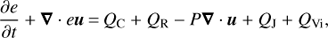
Using our method, we identify 145 306 features in 570 s of solar time. Figures 1 and 2 illustrate examples of our findings at t = 1130 s. We plot field lines over joule heating events to render the magnetic field topology in the corona with respect to the location of events. We choose 75 by 75 starting points for the field lines, equally distributed in the horizontal plane at the base of the corona. In Fig. 1, we represent the 2D slices of 3D joule heating events at the base of the corona together with contours of the vertical component of the magnetic field. Our aim is to identify any possible correlation between the magnetic field and density of heating events. Visual inspection shows that elongated and relatively large events form at low magnetic field magnitudes and preferably at regions where the magnetic field changes polarity. The relatively smallest identified events, however develop within regions of large magnetic field magnitudes.
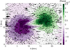 |
Fig. 1. Contours of the vertical component of the magnetic field at the base of the corona (at t = 1130 s) together with the bases of the identified joule heating events. |
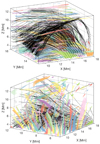 |
Fig. 2. Magnetic field lines over-plotted together with identified features, in which each colour represents a different feature, at t = 1130 s. Different panels illustrate different orientations of the x-y plane. |
The location of joule heating events is associated with the magnetic field configuration; it is required that there are large gradients in the magnetic field. The gradients of the magnetic field induce currents, which are partly dissipated through electric resistivity in the form of joule heating. We note that the magnitude of an event depends on the available magnetic energy. The magnetic energy in the corona is generally a function of the height above the photosphere, and does not vary significantly in the horizontal direction, because the magnetic field dominates the plasma and is configured in a force free state or at least very close to a force free state (Gudiksen & Nordlund 2005).
We calculate the amount of joule heating attributed to heating events by our algorithm in every snapshot. The evolution of the resolved energy density in the ROI is presented in Fig. 3, along with the evolution of the energy density of the magnetic field, and total energy density of the joule heating. We note that we employed the identification method on the energy density rate, and we converted the quantity to energy density by multiplying by the duration between snapshots.
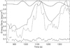 |
Fig. 3. Evolution of the following normalised quantities to their respective amplitude. Magnetic energy density (line) with maximum value 4.6 × 10⁸ erg cm−3, joule heating density of the identified features (dashed line) with maximum value 105 erg cm−3, total joule heating density released in the ROI (dash-dotted line) with maximum value 9.3 × 10⁵ erg cm−3, and ratio of resolved to total joule heating density (dots) are shown. |
The difference between total joule heating and joule heating attributed to heating events is what we refer to as residual heating, which on average consists of 90% of the total joule heating. We speculate that source of the residual energy is a combination of background heating, numerical noise, and unresolved events. Background heating may be due to a lower energy release mechanism that heats the region in a less or non-impulsive manner. Examples of this process are MHD waves that could induce currents or remnants of current sheets after an impulsive event that burn slowly (Janvier et al. 2014). Another possibility is the equivalent of the original nano-flare picture by Parker (1983), in which all flares were collections of nanoflares in small or large numbers; using this method to identify events we suffer the same problems as observers, in that we cannot distinguish a sea of low energy events from an almost constant background heating.
Assuming that the events we identify are not just a conglomeration of much smaller events, an interesting aspect of simulating the Sun is that you can resolve 3D heating events and follow their evolution. In Fig. 4, we show the evolution of energy release rate in four cases. Panels a and b represent long duration energetic events, which release energy in a non-monotonic fashion; panel c illustrates energy release of a nanoflare-like event that is resolved by four steps. Assuming that a heating event should have impulsive and gradual phases, panel d depicts an unresolved heating event because it has only a decline phase.
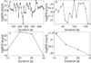 |
Fig. 4. Four cases of evolution of energy rate in heating events. Energy rate (ER) of each event is presented with an opened cycle in logarithmic scale at each time step; two successive points have an interval of 10 s. |
In this work we tried to identify as many heating events as possible using an unbiased method. The events we identify are believed to be mostly reconnection sites, and the reconnection site itself most likely leads to non-uniform heating all the way to the resistive scale. That is caused by the current sheets being inherently unstable in 3D, creating plasmoids of all sizes in the current sheets (Dahlburg et al. 2016). It is therefore questionable whether we can actually define and identify single events and this raises the question of whether the size we attribute to an event is not just a question of resolution. Testing different simulation grid sizes however falls outside the scope of this work, but it might be worth studying that in the future.
Other methods that could assign more of the total released joule energy are possible, but because of our motivation, this method seems the most appropriate. It is extremely difficult to correctly distribute the dissipated energy between the events, making it necessary to discard a large amount of energy in these high dissipation areas. The method we employ is selected to be conservative in the sense that we do not want to mistakenly attribute more energy to an event than we can be certain is part of that single event, and we are able to set strict rules that define an event.
3.1. Geometrical parameters
The shape and volume of each identified event varies significantly, as shown in Fig. 5 for the two events. To quantify this, we explore three geometrical parameters of 2D slices of a 3D event with respect to height z after we fit an ellipsoid to each slice. We choose to fit an ellipsoid at the 2D slice of each feature because the majority of shapes in the horizontal slice of the simulation box at the base of the corona, as illustrated in Fig. 1, could be approximated with such a surface. The parameters describing an ellipsoid are easy to be understood, and the process to do so is very easy and reproducible. The parameters we investigate are the following: cross-section (area), eccentricity, and orientation (between −90° and 90°) of the ellipsoid’s major axis with respect to the x-axis. In Fig. 5, we plot two examples of two apparently different shapes.
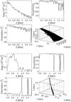 |
Fig. 5. Three geometrical parameters (area, orientation, and eccentricity) of 2D slices of two different 3D events calculated along height. The examples are identified at t = 1130 s of solar time and exhibit fun and spine-like shapes. The 3D structure is also presented in each case. |
We expect the area to increase or decrease coherently until the limit of our conservative resolution, i.e. around 4500 km2, unless a sudden and large magnetic field distortion occurs locally. In such cases, the geometrical parameters could change irregularly.
The example on the right of Fig. 5 represents a structure that has a very thin upper half part close to the resolution limit; hence we observe sharp spikes in the changes in orientation and eccentricity along height, which are probably not physical, but simply an effect of the resolution.
3.2. Histograms: Energy, mean volume, and duration
Isolating heating events enables us to explore different parameters, such as energy release, mean volume, and duration of heating events. Because the volume of each identified event evolves and changes with time, we calculate the mean volume of each identified event throughout its evolution. Mean volume is the total of volumes of an identified event at each snapshot for its total duration divided by the number of snapshots. These parameters can be interpreted collectively via histograms. For this reason, we calculate the differential size distribution (DSD), i.e. number of identified events per logarithmic bin width. In cases in which the DSDs can be approximated by a power-law distribution, we fit one that has the following expression:
 (2)
where the left-hand side is the DSD, α the power index, and A a constant.
(2)
where the left-hand side is the DSD, α the power index, and A a constant.
The bin width or number of bins is chosen with the Freedman-Diaconis rule, which is not very sensitive to outliers and is suitable for data with heavy-tailed distributions. This rule uses a bin width equal to 2 × IQR(x) × N−1/3, where IQR is the interquartile range of the data and N is the number of observations in the sample x.
Energy, event duration, and mean volume exhibit power-law distribution as illustrated in Figs. 6–8 respectively. To find the power index, we fit power-law functions using the χ2-minimisation technique. However, because of the knee on the lower end of the energy histogram, we choose the maximum DSD value and the corresponding parameter value to be the lower boundary at which we fit the power-law function. The minimum parameter value is considered to be the minimum resolved value and that is E0 = 1.1 × 10²⁰ erg. The power-law index is α = 1.41±0.01 and is fitted over 91% of total number of events. The energy released by the events that are not included in the power-law fitting have insignificant contribution to corona heating. The fitted power law in the duration histogram uses the total number of identified events and the slope is α = 2.87 ± 0.01. The three fitted power-law functions of the mean volume have slopes equal to α = 1.12, α = 2.35 ± 0.01, and α = 4.2 ± 0.25, which correspond to 74.54%, 25.25%, and 0.02% of the total number of events, respectively.
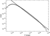 |
Fig. 6. DSD of the energy of the identified features in logarithmic scale along with the fitted power law. |
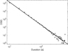 |
Fig. 7. DSD of the duration of events together with a fitted power law. |
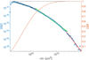 |
Fig. 8. DSD together with three fitted power-law functions and CDF of the averaged volume. The DSD is represented with the left vertical axis and CDF with the right vertical axis. |
In the histogram of mean volume (i.e. Fig. 8), we find that data can roughly be approximated by three broken power-law functions, but we find that the best way to describe the mean volume is via a CDF. The mean volume spans three orders of magnitude from volumes around 1021 cm3 up to volumes around 1024 cm3. We find that the CDF is very steep in the first 85% of volumes (volumes less than 2 × 1022 cm3), whereas the distribution in the rest becomes flatter.
Power laws and their indices are a useful tool for the distribution of a quantity and for checking the importance of smaller scales with respect to larger scales. However, fitting a power law is sometimes not trivial and the process usually adds bias to the analysis because it depends on several factors. For example, how well the data are distributed and the bin size and fitting techniques used. Panels a, b, and c in Fig. 4, show the energy rate evolution of three identified events, but could be a combination of several events occurring successively in close proximity. Especially in the case of the identified structure in panel c, where the energy rate increases almost four orders of magnitude in just 10 s, which is a rather peculiar behaviour for a single event. Our method is not able to resolve the events and they appear as a single event. Being unable to resolve every single event affects the derived power laws of all the heating event quantities, such as duration, energy, and volume. The effect on the power-law index can either preserve the index, if small events are just merged into larger events, but does so evenly along the whole energy spectrum. Generally, however this induced bias, flattens power laws and this means that we have calculated the lower limit of the power-law indices.
For general interest, we also look at the events tabulated in the classical event sizes. In Table 1 we have divided the events into three classes: Pico is for events releasing energy less than 1024 erg, nano for energy release ranging between 1024 and 1027 erg, and micro for events spanning between 1027 and 1030 erg. We calculate the standard deviation of the duration, the average and total energy and energy rate for each of the classes. We note that the uncertainty in duration is relatively large for the first two classes of events. In fact, the one standard deviation of duration for this cases suggests values lower than the 10 s time step used in this analysis. This behaviour happens owing to the very large spread of data points. We find that 93.5% of the identified events correspond to very small events (pico-events) and have an averaged duration equal to 13 s, while nano- (6.4%) and micro-events (0.03%) have averaged durations equal to 48 s and 283 s, respectively. Nano-events are responsible for releasing most of the energy followed by micro-flares.
Five parameters (fraction of events, total, mean (μ), standard deviation (σ), minimum, and maximum value) that describe the three classes of 145 306 heating events for duration, rate of released energy, and released energy.
4. Statistical analysis
Heating events identified can be viewed in two ways. There is the global view, in which parameters describe the collection of events, and the local view, in which the events themselves are analysed.
To investigate the global view, Fig. 9 shows the identified number of features (NOF), total energy density rate (Pdtot), resolved energy density rate (Pdr), and total volume of resolved events (Vr). These parameters are plotted as a function of time, and it can be seen that all of them behave somewhat stochastically. It can be seen that in broad terms, the number of identified events and their total volume follow each other well, which must mean that the volume distribution is almost constant in time. At the same time, the fraction of the energy density that is identified as events is then also almost constant in time. The combination of the two sets of curves shows that even though the volume of the events is almost constant, both the energy density released and the fraction of that which is identified changes by almost a factor 10.
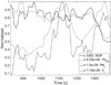 |
Fig. 9. Time series of the following normalised quantities to their respective maximum quantities: NOF (full), total energy rate density (dashed), resolved energy density rate (dash-dotted), and resolved volume (dotted). |
The local view compares parameters for each of the identified events. Figure 10 compares the duration of each of the events with the total energy density of the events and the average volume of the event. It is interesting to see how large the spread in energy is for the short-lived events, where the spread is seven orders of magnitude, while the longest living events only vary in total energy output by roughly a factor 10. Similarly, the average volume of the events vary by more than two orders of magnitude for the short-lived events, while the long-lived events are generally all of a volume close to 1023 cm3. Comparing the average volume with the energy density released by the events, shows again large spreads, but the spread is almost the same for both variables.
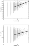 |
Fig. 10. Top: Total energy vs. duration of all identified features. A power-law fit is attempted for the data points that have durations more than 50 s. Those data points correspond to 0.2% of the total number of events (3083 out of 145 306). The power-law index is α = 2.55 ± 0.05. Bottom: Same as in top panel for mean volume vs. duration. The power-law index is α = 0.56 ± 0.01. |
5. Discussion and conclusions
In MHD simulations, images such as Figs. 1 and 2 can shed some light on the details. The general trend is that the most elongated and also largest heating events are formed where the vertical component of the magnetic field, Bz, is small and usually at the interfaces between regions with different connectivity (white and light shades of purple and green areas). Large concentrations of smaller events are present predominately in regions with high magnetic field strengths, however the number of events seems to be quenched in regions with the highest flux densities. The explanation for that can be the fact that the stronger the magnetic field, the more difficult it is to form magnetic field gradients.
The non-constant nature of the identified structures is confirmed in the 2D geometrical parameters of the events cuts in Fig. 5. While identified structures tilt and extend to any direction in the simulation box, the parameters change significantly from one height to another. Such irregularities might occur owing to large gradients of the magnetic field, viz. region exhibiting high probability for magnetic reconnection, but could also be evidence that the cross sections of the currents are fractal-like in structure.
The close correlation between the global parameters in Fig. 9 shows that the volume taken up by the heating events and the total number of these events is almost constant in time. In principle, we cannot conclude anything about the distribution of the event volumes from this evidence alone. But since neither the total volume or the total number of events change and the inspection of the DSD for energy shows no difference in shape throughout the simulated timespan, we must conclude that the size distribution and energy distribution of the events are both constant; this is the case in spite of the large changes in the total energy and resolved energy at about t = 1100 s.
The resolved energy density rate follows the total energy density rate, which can also be seen in Fig. 3. As the method consistently catches roughly 10% of the released energy, there is a reason to believe that the residual heating is not a due to a different physical mechanism, as that most likely would not produce a constant ratio when the total energy dissipated by more than a factor two.
Figures 10 and 11 show that the energy in the heating events are not given. The total energy delivered by a single heating event is highly dependent on the duration and less dependent on the average volume. Since there is an enormous spread in total energy for heating events of the same duration, it means that the scaling laws between duration, volume and energy are somewhat curious. Initially we imagined that this might be because these scaling laws were between integrated values in the 4D space time, but the scalings between the 4D variables themselves are worse. It is not easy to produce simple arguments regarding why the scaling law indices have the found magnitudes and requires the energy density rates to be complicated functions. Whether these power laws are simply an expression of the crowding of many small heating events (Parker’s nano-flares) is outside the scope of this paper.
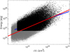 |
Fig. 11. Energy vs. mean volume together with power-law fit of the data points that correspond to a duration larger than 50 s as identified (blue) in Fig. 10 and a power-law fit assuming all data points (red line). The power-law index of the former is α = 1.35 ± 0.01, and corresponds to 53% of the total number of heating events (76 538 out of 145 306), while the power law of the latter is α = 1.74 ± 0.01. |
Identifying single or groups of events might affect the power-law distribution of various parameters such as duration and energy, however we still can derive some conclusions on the impact of heating events on coronal heating. In our results, we observe that the total joule energy density is smaller by more than two orders of magnitude than the energy density of the magnetic field in the corona (Fig. 3). As a consequence, only a fraction of the magnetic energy is needed to heat the corona. A fraction of the total joule heating in the corona is attributed to energy released from impulsive events. This fraction varies between 2% and 14% indicating the dynamic and intermittent character of heating from impulsive events. In general, the energy rate related to heating events corresponds to 8% of the total energy rate of joule heating released in the corona throughout the total time of investigation. The energy rate released from heating events is approximately 5.4 × 1027 erg s−1 in a volume equal to 24 × 24 × 9.5 Mm3; the resolved energy rate corresponds to energy flux that is 9.4 × 10⁸ erg cm−2 s−1. Therefore, the energy flux from impulsive events is two orders of magnitude larger than the typical radiative loss from the QS, i.e. 8 × 10⁵−106 erg cm−2 s−1 (Withbroe & Noyes 1977; Withbroe 1988). We note however that a big part of that flux is also transported via thermal conduction into the transition region, for example pulses of thermal conduction as described in the dissipative thermal flare model (Brown et al. 1979; Smith & Lilliequist 1979).
In this work, we are able to push the lower boundary of identified events down to the energy magnitude of 1020 erg, i.e. minimum value of pico-size events. In addition, we derive the duration power index (2.87); this – together with the fact that 75% of the identified events are not resolved temporally, i.e. they live less than 10 s – suggest that the majority of events are short lived. If this is the case, then observers would need a very short temporal cadence in their observations to capture such short-lived events. Moreover, we find that our volume data are distributed in a way that follow three broken power-law functions, for which we agree with the literature for only the slope that describes the smallest volumes and corresponds to 75% of the total number of events. The cumulative function of the quantity suggests that the majority of events have relatively small volumes. Generally, we find that there is no general rule for how energy is released in individual heating events because results are biased because of event overlap. In Fig. 4 for example, we see that small-scale events can be short and impulsive with single peaks and their impulsive phase sometimes last longer than the decay phase, while in some other instances the opposite occurs. These behaviours however, could also be artefacts of the identification method.
Identifying the contribution of small-scale events in heating the solar corona by employing numerical simulations and a conservative identification method has been proven not to be an easy task. Certainly, the results presented in this work are unable to give a clear answer to the question of whether coronal heating is dominated by reconnection events and their distribution. But the results point in a certain direction. Numerous and short-lived, with small spatial extent, and stochastic nature are the most abundant population of events in this work. We calculate the energy flux corresponding to nano-events, events with energy within the nanoflare energy range, and we find that this is more than enough to sustain the energy requirements of the corona. Like observers, we also identify a flat energy power-law distribution. This is because small events cluster together forming larger events. A piece of evidence that confirms the clustering of small heating events is the multiple peaks in the evolution of energy rate (panels a and b in Fig. 4). Therefore, an identification method is not able to resolve events temporally and spatially below certain limits owing to physical (e.g. background heating) and technical limitations (e.g. threshold criteria). Regardless of the identified sizes of the heating, most of the events occur in regions with low magnetic fields because magnetic fields there can be contorted with ease. However, in regions where the magnetic field magnitudes are large and changes are harder, the resulting heating events release larger amounts of energy.
The present work is a first step towards finding the contribution of small-scale events related to a highly distorted magnetic field in a specific coronal environment and the values we report seem to be lower limits. It is important, for all future investigations of small-scale heating events, that observational and methodological biases are investigated when an attempt is made to find the elusive power-law index α for the distribution of heating events in the solar corona.
Acknowledgments
This research was supported by the Research Council of Norway through its Centres of Excellence scheme, Project Number 262622, and through grants of computing time from the Programme for Supercomputing.
References
- Aschwanden, M. J., & Freeland, S. L. 2012, ApJ, 754, 112 [NASA ADS] [CrossRef] [Google Scholar]
- Aschwanden, M. J., & Parnell, C. E. 2002, ApJ, 572, 1048 [NASA ADS] [CrossRef] [Google Scholar]
- Aschwanden, M. J., & Shimizu, T. 2013, ApJ, 776, 132 [NASA ADS] [CrossRef] [Google Scholar]
- Aschwanden, M. J., Crosby, N. B., Dimitropoulou, M., 2016, Space Sci. Rev. 198, 47 [NASA ADS] [CrossRef] [Google Scholar]
- Asgari-Targhi, M., & van Ballegooijen, A. A. 2012, ApJ, 746, 81 [NASA ADS] [CrossRef] [Google Scholar]
- Aulanier, G., Pariat, E., Démoulin, P., & DeVore, C. R. 2006, Sol. Phys., 238, 347 [NASA ADS] [CrossRef] [Google Scholar]
- Benz, A. O., & Krucker, S. 2002, ApJ, 568, 413 [NASA ADS] [CrossRef] [Google Scholar]
- Brown, J. C., Spicer, D. S., & Melrose, D. B. 1979, ApJ, 228, 592 [NASA ADS] [CrossRef] [Google Scholar]
- Carlsson, M., & Stein, R. 2002, ApJ, 572, 626 [NASA ADS] [CrossRef] [Google Scholar]
- Carlsson, M., Hansteen, V. H., de Pontieu, B., et al. 2007, PASJ, 59, S663 [Google Scholar]
- Carlsson, M., Hansteen, V. H., Gudiksen, B. V., Leenaarts, J., & De Pontieu, B. 2016, A&A, 585, A4 [NASA ADS] [CrossRef] [EDP Sciences] [Google Scholar]
- Christe, S., Hannah, I. G., Krucker, S., McTiernan, J., & Lin, R. P. 2008, ApJ, 677, 1385 [NASA ADS] [CrossRef] [Google Scholar]
- Collins, T. J. 2007, Biotechniques, 43, 25 [CrossRef] [Google Scholar]
- Crosby, N. B., Aschwanden, M. J., & Dennis, B. R. 1993, Sol. Phys., 143, 275 [NASA ADS] [CrossRef] [Google Scholar]
- Dahlburg, R. B., Einaudi, G., Taylor, B. D., et al. 2016, ApJ, 817, 47 [NASA ADS] [CrossRef] [Google Scholar]
- Drake, J. F. 1971, Sol. Phys., 16, 152 [NASA ADS] [CrossRef] [Google Scholar]
- Galsgaard, K., & Nordlund, Å. 1996, J. Geophys. Res., 101, 13445 [NASA ADS] [CrossRef] [Google Scholar]
- Gesztelyi, L., Gerlei, O., Karlicky, M., Farnik, F., & Valnicek, B. 1986, in The lower atmosphere of solar flares; Proceedings of the Solar Maximum Mission Symposium, August, 1985 (A87-26201 10-92), ed. D. F. Neidig, Sunspot NM, National Solar Observatory, 163 [Google Scholar]
- Gudiksen, B. V., & Nordlund, Å. 2005, ApJ, 618, 1020 [NASA ADS] [CrossRef] [Google Scholar]
- Gudiksen, B. V., Carlsson, M., Hansteen, V. H., et al. 2011, A&A, 531, A154 [NASA ADS] [CrossRef] [EDP Sciences] [Google Scholar]
- Gul-Mohammed, J., Arganda-Carreras, I., Andrey, P., Galy, V., & Boudier, T. 2014, BMC Bioinformatics, 15, 9 [CrossRef] [Google Scholar]
- Hannah, I. G., Hudson, H. S., Battaglia, M., et al. 2011, Space Sci. Rev., 159, 263 [NASA ADS] [CrossRef] [Google Scholar]
- Hansteen, V., Guerreiro, N., De Pontieu, B., & Carlsson, M. 2015, ApJ, 811, 106 [NASA ADS] [CrossRef] [Google Scholar]
- Hara, H., & Ichimoto, K. 1999, ApJ, 513, 969 [NASA ADS] [CrossRef] [Google Scholar]
- Hayek, W., Asplund, M., Carlsson, M., et al. 2010, A&A, 517, A49 [NASA ADS] [CrossRef] [EDP Sciences] [Google Scholar]
- Hudson, H. S. 1991, Sol. Phys., 133, 357 [Google Scholar]
- Janvier, M., Aulanier, G., Bommier, V., et al. 2014, ApJ, 788, 60 [NASA ADS] [CrossRef] [Google Scholar]
- Kanella, C., & Gudiksen, B. V. 2017, Astron. Astrophys., 603, A83 [Google Scholar]
- Klimchuk, J. A. 2006, Sol. Phys., 234, 41 [NASA ADS] [CrossRef] [Google Scholar]
- Low, B. C. 1990, ARA&A, 28, 491 [NASA ADS] [CrossRef] [Google Scholar]
- Morales, L., & Charbonneau, P. 2009, ApJ, 698, 1893 [NASA ADS] [CrossRef] [Google Scholar]
- Nordlund, A., & Galsgaard, K. 2012, in EGU General Assembly Conference Abstracts, eds. A. Abbasi, & N. Giesen, EGU General Assembly Conference Abstracts, 14, 12646 [Google Scholar]
- Ollion, J., Cochennec, J., Loll, F., Escudé, C., & Boudier, T. 2013, Bioinformatics (Oxford, England), 29, 1840 [CrossRef] [Google Scholar]
- Parker, E. N. 1972, ApJ, 174, 499 [NASA ADS] [CrossRef] [Google Scholar]
- Parker, E. N. 1983, ApJ, 264, 635 [NASA ADS] [CrossRef] [Google Scholar]
- Parker, E. N. 1988, ApJ, 330, 474 [Google Scholar]
- Pérez Enriquez, R., & Miroshnichenko, L. I. 1999, Sol. Phys., 188, 169 [NASA ADS] [CrossRef] [Google Scholar]
- Smith, D. F., & Lilliequist, C. G. 1979, ApJ, 232, 582 [NASA ADS] [CrossRef] [Google Scholar]
- Spitzer, L. 1962, Physics of Fully Ionized Gases (New York: Interscience) [Google Scholar]
- Tomczyk, S., McIntosh, S. W., Keil, S. L., et al. 2007, Science, 317, 1192 [NASA ADS] [CrossRef] [PubMed] [Google Scholar]
- van Ballegooijen, A. A. 1986, ApJ, 311, 1001 [NASA ADS] [CrossRef] [Google Scholar]
- van Ballegooijen, A. A., Asgari-Targhi, M., Cranmer, S. R., & DeLuca, E. E. 2011, ApJ, 736, 3 [NASA ADS] [CrossRef] [Google Scholar]
- Withbroe, G. L. 1988, ApJ, 325, 442 [NASA ADS] [CrossRef] [Google Scholar]
- Withbroe, G. L., & Noyes, R. W. 1977, ARA&A, 15, 363 [NASA ADS] [CrossRef] [Google Scholar]
All Tables
Five parameters (fraction of events, total, mean (μ), standard deviation (σ), minimum, and maximum value) that describe the three classes of 145 306 heating events for duration, rate of released energy, and released energy.
All Figures
|
Fig. 1. Contours of the vertical component of the magnetic field at the base of the corona (at t = 1130 s) together with the bases of the identified joule heating events. |
| In the text | |
|
Fig. 2. Magnetic field lines over-plotted together with identified features, in which each colour represents a different feature, at t = 1130 s. Different panels illustrate different orientations of the x-y plane. |
| In the text | |
|
Fig. 3. Evolution of the following normalised quantities to their respective amplitude. Magnetic energy density (line) with maximum value 4.6 × 10⁸ erg cm−3, joule heating density of the identified features (dashed line) with maximum value 105 erg cm−3, total joule heating density released in the ROI (dash-dotted line) with maximum value 9.3 × 10⁵ erg cm−3, and ratio of resolved to total joule heating density (dots) are shown. |
| In the text | |
|
Fig. 4. Four cases of evolution of energy rate in heating events. Energy rate (ER) of each event is presented with an opened cycle in logarithmic scale at each time step; two successive points have an interval of 10 s. |
| In the text | |
|
Fig. 5. Three geometrical parameters (area, orientation, and eccentricity) of 2D slices of two different 3D events calculated along height. The examples are identified at t = 1130 s of solar time and exhibit fun and spine-like shapes. The 3D structure is also presented in each case. |
| In the text | |
|
Fig. 6. DSD of the energy of the identified features in logarithmic scale along with the fitted power law. |
| In the text | |
|
Fig. 7. DSD of the duration of events together with a fitted power law. |
| In the text | |
|
Fig. 8. DSD together with three fitted power-law functions and CDF of the averaged volume. The DSD is represented with the left vertical axis and CDF with the right vertical axis. |
| In the text | |
|
Fig. 9. Time series of the following normalised quantities to their respective maximum quantities: NOF (full), total energy rate density (dashed), resolved energy density rate (dash-dotted), and resolved volume (dotted). |
| In the text | |
|
Fig. 10. Top: Total energy vs. duration of all identified features. A power-law fit is attempted for the data points that have durations more than 50 s. Those data points correspond to 0.2% of the total number of events (3083 out of 145 306). The power-law index is α = 2.55 ± 0.05. Bottom: Same as in top panel for mean volume vs. duration. The power-law index is α = 0.56 ± 0.01. |
| In the text | |
|
Fig. 11. Energy vs. mean volume together with power-law fit of the data points that correspond to a duration larger than 50 s as identified (blue) in Fig. 10 and a power-law fit assuming all data points (red line). The power-law index of the former is α = 1.35 ± 0.01, and corresponds to 53% of the total number of heating events (76 538 out of 145 306), while the power law of the latter is α = 1.74 ± 0.01. |
| In the text | |
Current usage metrics show cumulative count of Article Views (full-text article views including HTML views, PDF and ePub downloads, according to the available data) and Abstracts Views on Vision4Press platform.
Data correspond to usage on the plateform after 2015. The current usage metrics is available 48-96 hours after online publication and is updated daily on week days.
Initial download of the metrics may take a while.