Fig. 15
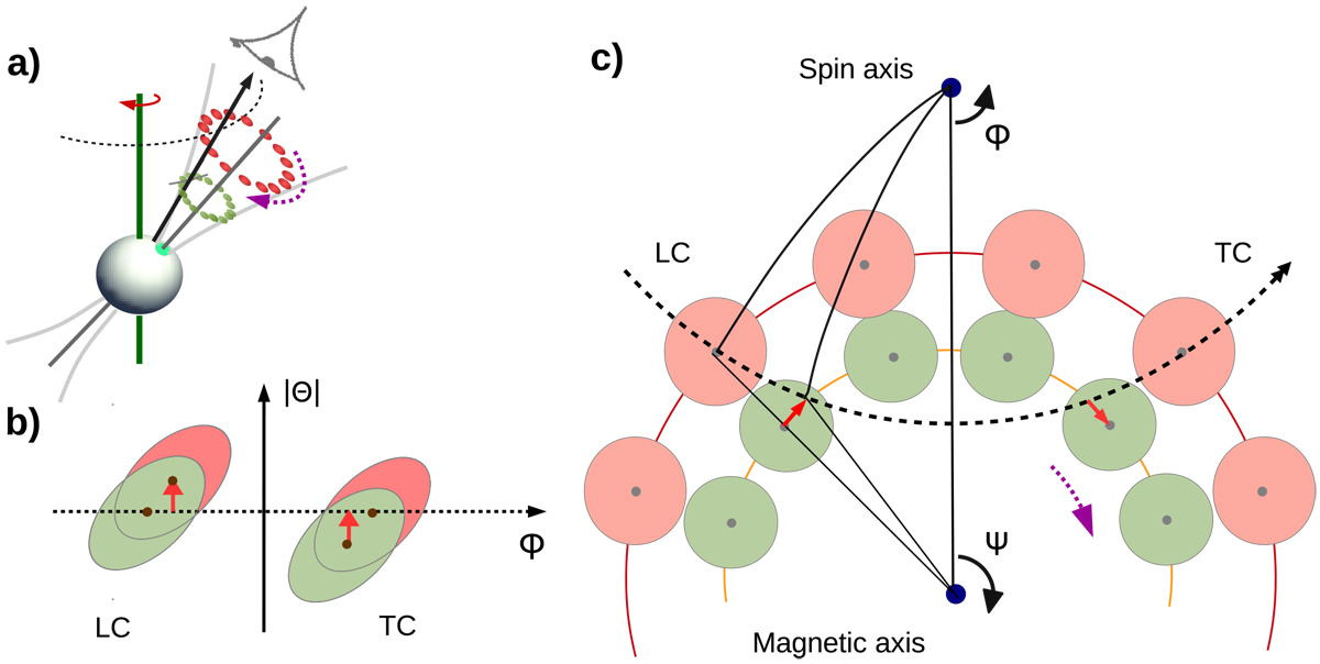
Cartoon model of the drift track evolution: (a) general view on the system (inside traverse geometry, pulsar is rotating clockwise), similar to Fig. 1, but with individual sparks at two different radio frequencies, νlo (red) and νhi (green). According to the RFM, emission at νlo comes fromhigher altitudes, where the opening angle of the dipole field lines is larger. The modfolds at these two frequencies are shown in (b). The carousel configuration corresponding to the moment marked with the dotted horizontal line in (b) is shown in (c). The violet arrows in (a) and (c) mark the direction of the carousel rotation (see text for more details). The black arrows show increasing longitude, ϕ, and the magnetic azimuth, ψ, both measured from the fiducial longitude. At this moment, the LOS sweeps through the spark centres at νlo and misses the spark centres at νhi. For the leading component (LC), the rotating carousel needs more time to bring the spark centre to the LOS. The drift phase Θ is directly proportional to time (Eq. (16)), thus |ΘLC(νhi)| > |ΘLC(νlo)|. The spherical triangles defined by the spin axis, magnetic axis, and the point where the LOS passes through the emission cone (black lines) are identical to the triangle in the inset of Fig. 1.
Current usage metrics show cumulative count of Article Views (full-text article views including HTML views, PDF and ePub downloads, according to the available data) and Abstracts Views on Vision4Press platform.
Data correspond to usage on the plateform after 2015. The current usage metrics is available 48-96 hours after online publication and is updated daily on week days.
Initial download of the metrics may take a while.