| Issue |
A&A
Volume 604, August 2017
|
|
|---|---|---|
| Article Number | L1 | |
| Number of page(s) | 9 | |
| Section | Letters | |
| DOI | https://doi.org/10.1051/0004-6361/201730766 | |
| Published online | 27 July 2017 | |
CALYPSO view of SVS 13A with PdBI: Multiple jet sources
1 Institut de Radioastronomie Millimétrique (IRAM), 300 rue de la Piscine, 38406 Saint-Martin d’Hères, France
e-mail: lefevre@iram.fr
2 LERMA, Observatoire de Paris, CNRS, 61 Av. de l’Observatoire, 75014 Paris, France
3 Laboratoire AIM-Paris-Saclay, CEA/DSM/Irfu – CNRS – Université Paris Diderot, CE-Saclay, 91191 Gif-sur-Yvette, France
4 Osservatorio Astrofisico di Arcetri, Largo Enrico Fermi 5, 50125 Florence, Italy
5 Max-Planck-Institut für Radioastronomie, Auf dem Hügel 69, 53121 Bonn, Germany
6 Univ. Grenoble Alpes, CNRS, IPAG, 38000 Grenoble, France
Received: 10 March 2017
Accepted: 6 July 2017
Aims. We aim to clarify the origin of the multiple jet features emanating from the binary protostar SVS 13A (=VLA4A/VLA4B).
Methods. We used the Plateau de Bure Interferometer to map at 0.3–0.8′′ (~70–190 au) dust emission at 1.4 mm, CO(2–1), SiO(5–4), SO(65–54). Revised proper motions for VLA4A/4B and jet wiggling models are computed to clarify their respective contribution.
Results. VLA4A shows compact dust emission suggestive of a disk <50 au, and is the hot corino source, while CO/SiO/SO counterparts to the small-scale H2 jet originate from VLA4B and reveal the jet variable velocity structure. This jet exhibits ≃ 3″ wiggling consistent with orbital motion around a yet undetected ≃20–30 au companion to VLA4B, or jet precession. Jet wiggling combined with velocity variability can explain the large apparent angular momentum in CO bullets. We also uncover a synchronicity between CO jet bullets and knots in the HH7–11 chain demonstrating that they trace two distinct jets. Their ≃300 yr twin outburst period may be triggered by close perihelion approach of VLA4A in an eccentric orbit around VLA4B. A third jet is tentatively seen at PA ≃ 0°.
Conclusions. SVS13 A harbors at least 2 and possibly 3 distinct jet sources. The CO and HH7-11 jets are launched from quasi-coplanar disks, separated by 20–70 au. Their synchronous major events every 300 yr favor external triggering by close binary interactions, a scenario also invoked for FU Or outbursts.
Key words: stars: protostars / stars: low-mass / ISM: jets and outflows / ISM: individual objects: NGC 1333 SVS 13A
© ESO, 2017
1. Introduction
The role of close stellar encounters in accretion and ejection bursts in young stars is a debated issue (Reipurth et al. 2014; Audard et al. 2014, and references therein). An interesting target of study in this context is SVS 13A, a 0.3″ (70 au) binary solar-type protostar (VLA4A,VLA4B; Anglada et al. 2000) in NGC 1333 (d ≃ 235 pc, Hirota et al. 2008) with multiple signs of ejection bursts. SVS 13A is the candidate source of the HH7–11 chain of optica /H2 knots (Davis et al. 2000), drives high-velocity CO bullets (Bachiller et al. 2000, hereafter B00), and hosts small scale [Fe II] jet with H2 arcs (see Hodapp & Chini 2014, hereafter HC14, and references therein). An unusually large angular momentum extraction by CO outbursts, compared to other rotating outflows like DG Tau, was recently claimed from SMA maps at 3′′ resolution (Chen et al. 2016). Here we present the highest angular resolution (0.3′′−0.8′′) study of the SVS13 A system in dust continuum, CO, SiO and SO, obtained in the frame of the CALYPSO (Continuum And Lines in Young ProtoStellar Objects1) Large Program at the IRAM Plateau de Bure inteferometer (hereafter PdBI, Maury et al., in prep.). The high astrometric precision, angular resolution, and sensitivity reveal the jet structure in unprecedented detail and the key role of multiplicity in its outstanding outflow properties.
2. Observations and data reduction
CALYPSO data of SVS 13A were taken with the six antennas of the PdBI in A and C configurations in the winters of 2011, 2012, and 2013, with baselines ranging from 24 m to 760 m. The typical system temperature and water vapor were 140 K and ~2 mm.We used the WideX backend with 2 MHz channels (~2.8 km s-1) to extract a range of ±300 km s-1 around SiO(5−4), SO(65 − 54) and CO(2−1) at 217.10498, 219.949442, and 230.53800 GHz, respectively. Data calibration was performed with the GILDAS–CLIC software. Continuum was obtained by averaging line–free channels over the 4 GHz WideX band centered at 219 GHz. Self-calibration was performed on the continuum uv-data. The same gain tables were then applied to all WideX uv-tables, and images cleaned using natural weighting, with a synthesized beam of 0.83″ × 0.56″ in continuum, SiO and SO and 0.76″ × 0.5″ in CO. Each line cube was continuum-subtracted by baseline fitting in the image plane, and also corrected from primary beam attenuation. A high-resolution continuum image was generated from A configuration data alone with uniform weighting, resulting in a 0.52″ × 0.31″ beam. The absolute astrometric precision based on phase calibrators is ≃20 mas. Absolute flux calibration was based on MWC349, with an uncertainty of 20%. The 1σ noise level is 0.7 and 1.2 mJy/beam in continuum for A and A+C configurations, respectively, and 1.7 mJy/beam ≃ 0.1 K per channel for the lines.
3. Results
3.1. Dust and COM distribution in SVS 13A
 |
Fig. 1 Top: 1.4 mm continuum maps of SVS13 A using A configuration (left) and A+C (right). Contours start at 3σ and 10σ respectively, and increase by 10σ. Crosses show the positions of VLA4B and VLA4A, corrected for our proper motions (Appendix A). The synthesized beam is plotted in the bottom left corner. Bottom: residuals after removal of a point source fit to the A config. uv-data at the position of VLA4A. The color scale is in mJy/beam. |
The 1.4 mm continuum maps are presented in Fig. 1. The A-configuration map reveals an EW elongation indicating similar peak fluxes towards both sources of the close (0.3′′) binary system VLA4A/B, marginally resolved by our longest baselines. To estimate the flux of each component, we computed updated proper motions including the latest data of Tobin et al. (2016) and deduced accurate positions at the time of the CALYPSO observations (Appendix A). By fitting source models at these positions to the A and A+C uv-data, we find that VLA4B is extended, while VLA4A can be reproduced by an unresolved component alone (radius <0.2′′≃ 50 au) of flux ≃40 ± 10 mJy (where error bars include position and calibration uncertainties). The free-free contamination of VLA4A at 1.4 mm, extrapolating the 3.6−1 cm fluxes of Anglada et al. (2000) and Tobin et al. (2016), is only ≃1.5 mJy. Hence, we find that VLA4A harbors compact circumstellar dust, suggestive of a disk of radius <50 au, unlike previously believed (Anglada et al. 2004). Assuming optically thin emission from compact disk or inner envelope, and using Eqs. (1) and (2) of Motte & André (2001) with L⋆ = 28 L⊙ (from Herschel 70 μm, André et al. 2010), we estimate an inner circumstellar mass of ≃0.01 M⊙ (Tdust ~ 40 − 100 K at 50 au, with uncertainties of a factor three mostly from dust emissivity). Interestingly, complex organic molecules (COMs) from the hot corino of SVS13A (e.g. López-Sepulcre et al. 2015; De Simone et al. 2017) peak on or close to VLA4A (see Fig. 2 and Belloche et al., in prep.), confirming VLA4A has dense circumstellar material. Residuals after removing the point source on VLA4A (Fig. 1, bottom row) show dust emission extended on scales of at least ~2″ peaking on VLA4B (total flux ~200 ± 25 mJy, free-free contamination < 10 mJy). This component may be reproduced by the inner parts of a larger circumbinary envelope (with details to be developed in Maury et al., in prep.).
3.2. Origin and kinematics of the blueshifted molecular jet
 |
Fig. 2 Maps of CO, SiO and SO integrated over three VLSR ranges: EHV = –150 to –68 km s-1, IHV = –68 to –28 km s-1, SHV = –28 to − 3 km s-1. Red and black crosses denote VLA4B and VLA4A, respectively. The compact emission peaked on VLA4A is entirely due to COMs (identified in Figs. D.2 and D.3). The bottom right panel shows Fig. 4 of HC14 registered on VLA4B. Their main H2 features are outlined in white (cf. text and expanded view in Fig. C.1). They are reported in red in the other panels. The black line displays PA = 155° (B00). |
The left column of Fig. 2 shows that the extremely-high velocity (hereafter EHV) blueshifted (with respect to Vsys = 8.5 km s-1) CO jet found by B00 is resolved into a series of knots, also detected in SiO and SO. It also reveals an excellent correspondence with the H2 outflow features of HC14 – namely a small circular “bubble” (denoted (a)), two H2 arcs (denoted (b) and (c)), and a fainter “linear feature” joining (a) and (b) – when these features are registered on VLA4B (see Fig. 2). In contrast, a systematic shift appears if they are registered on VLA4A (see Appendix B). Hence, the CALYPSO data unambiguously identify VLA4B as the base of the small-scale CO / H2 jet from SVS 13A, and hence confirming previous assumption2 by HC14 that VLA4B was the near-infrared (NIR) source in their observations. The spatial agreement between tracers with very different excitation conditions (2000 K for H2, less than a few 100 K for CALYPSO) implies emission in shock fronts with strong temperature gradients below our angular resolution. CALYPSO data thus reveal the kinematics of H2 features at unprecedented spectral resolution (apart from bubble (a) that is strongly beam diluted).
Position-velocity (PV) diagrams along the mean jet axis (PA = 155°, B00) are shown in Fig. 3, and individual channel maps in Appendix D. The EHV jet velocity fluctuates strongly with distance. Along the linear H2 feature it shows apparent deceleration from VLSR ≃ − 100 km s-1 near bubble (a) to − 75 ± 5 km s-1 at arc (b), then increases again to − 90 ± 3 km s-1 at arc (c). Combined with the arc (c) proper motion of 31.4 mas/yr = 35 km s-1 (HC14) we infer an inclination i ≃ 20° for this feature, similar to the center of the inner bubble (i ≃ 18°, HC14). The jet velocity further increases beyond arc (c) up to –115 km s-1 at 4′′ and oscillates between –115 and –90 km s-1 on larger scale (see Fig. 3). No redshifted EHV counterjet is detected, as noted by B00.
 |
Fig. 3 PV diagrams along PA = 155°. Dashed lines indicate the reference position (VLA 4B) and the systemic velocity Vsys = 8.5 km s-1 (from SO). Contours start at 3σ with steps of 14σ for SiO(5–4), 7σ for SO(65 − 54) and 21σ for CO(2–1). The color scale displays the intensity in K. Vertical dotted lines indicate the position of the H2 features of HC14 as labeled in Fig. 2. Red and black crosses show velocities for which the molecules peak on arcs (b) and (c), respectively. The orange arrows indicate contamination by complex organic molecules (COMs). |
The intermediate and standard high-velocity ranges (IHV, SHV) show an apparent accelerating pattern from ≃–20 km s-1 near the source to − 70 km s-1 at arc (b) (Fig. 3). CALYPSO maps in this velocity range (Fig. 2) reveal U-shaped cavities opening away from the source in CO, and broad extended wings behind arcs (b) and (c) in SiO and SO, suggestive of material entrained by jet bowshocks.
3.3. Jet wiggling and limits on jet rotation
Figure 4 shows a slightly enlarged region of the blueshifted jet in CO and SiO. It reveals that the S-shaped morphology seen in H2 (HC14) is part of a coherent wiggling pattern traced in SiO and CO out to 5−6′′, with a (projected) half-amplitude αobs ≃ 10° and wavelength λobs ≃ 3′′ (700 au), shorter than the 8.5′′suggested by Chen et al. (2016). We show in Fig. 4 that this pattern is very well reproduced by simple models of circular orbital motion or jet precession of period ≃100 yr (see Appendix C for details). In the orbital scenario, a separation of 70 au (i.e. VLA4A) would imply, through Kepler’s third law, a total mass Mtot ≃ 7 − 35 M⊙ (for eccentricity e = 0.8 − 0), which is excluded. A realistic Mtot < 4 M⊙ would thus require a (so far unseen) closer companion 20–32 au from VLA4B, making SVS13A a hierarchical triple. Its non-detection in NIR images (HC14) implies it would be substantially fainter than VLA4B. Alternatively, CO jet wiggling could be due to jet precession, with the physical cause remaining unclear: rigid disk precession induced by a planetary mass body at 0.5 au, or non-rigid precession of a larger disk, for which models are still lacking (see Appendix C). Both the orbiting and precessing jet models originating from VLA4B reproduce the [FeII] micro-jet observed by HC14 within 0.3′′, while if the CO jet originates from a companion to VLA4B, the truncation of the [FeII] jet might be explained by jet collision near the H2 bubble center (see zoom in Fig. C.1).
 |
Fig. 4 Left panels: centroid velocity (color) and integrated intensity (contours) in CO(2–1) EHV a) and SiO(5–4) EHV+IHV c). Best fit wiggling models are overplotted in red, orange, and green (see Appendix C for details). Right panels: transverse PV diagrams of CO(2–1) b) and SiO(5–4) d) at the three distances indicated in each sub-panel, and perpendicular to mean PA = 155°. Red lines are visual cues. |
We stress that the combination of CO jet wiggling and velocity variability creates transverse velocity gradients, that could be mistaken for jet rotation at low angular resolution. A likely example is the gradient reported by Chen et al. (2016) across “Bullet 2”, the EHV CO bullet located ≃10′′ further south (see Fig. 5): its lateral extent (±2.5′′) matches precisely the extrapolation of small-scale wiggling (αobs ≃ 10°) and its velocity range (VLSR ≃ –105 to –90 km s-1) is typical of radial velocity fluctuations along the inner EHV jet (Sect. 3.2). To constrain the level of rotation in the EHV jet with minimal confusion from wiggling, we present in Fig. 4 transverse PV cuts in CO and SiO within 1.8″ of the source. No consistent transverse gradient is found at our resolution. The jet radius ≤0.4′′ and velocity width <10 km s-1, corrected for an inclination of 20°, set a conservative upper limit to the specific angular momentum of 1500 au km s-1, four times smaller than in Chen et al. (2016). If the jet is steady, axisymmetric, and magneto-centrifugally accelerated to 100 km s-1 from a Keplerian disk, the launch radius would be < 4 au × (M⋆/M⊙)1 / 3 (Anderson et al. 2003).
3.4. Evidence for multiple jets and origin of HH7–11
 |
Fig. 5 Wide field CO maps of the SVS 13A outflow corrected from primary beam attenuation, in three velocity ranges: blue: EHV (− 150 to − 68 km s-1), green: IHV (− 68 to − 28 km s-1), red: Sred (+10 to +40 km s-1). The three arrows show the directions of the three jets: to HH11 (PA = 133°, pink), the wiggling H2/CO jet (PA = 155 ± 10°, solid and dashed blue lines) and the third jet suggested by velocity sign reversal (PA ≃ 0°, gray). The pink cross shows the SiO/SO knot X at –28 km s-1. Pink contours show HH11 extension (Noriega-Crespo & Garnavich 2001). Dotted black contours outline the EHV Bullet 2 as mapped by B00. Dashed segment shows where Chen et al. (2016) reported possible rotation. VLA4A/4B are indicated as yellow crosses. |
B00 noted that the CO EHV jet at PA ≃ 155° lies in a markedly different direction from the chain of optical Herbig-Haro (hereafter HH) objects HH7-11, at PA ≃ 130°, and interpreted it as a recent change of ejection direction in a single jet. Below we argue that these two flows are actually driven by two distinct sources. First, ejection along HH7-11 still seems active: Fig. 4c reveals an unresolved SiO knot of unknown origin (≥15σ in both SiO and SO, and denoted “knot X” hereafter) at a smaller PA and much lower radial velocity (− 33 km s-1<VLSR< − 20 km s-1) than the local EHV CO jet. These properties are more typical of H2 emission toward the wings of HH10–11 (Davis et al. 2000, 2001), suggesting a new event in the HH chain. A faint hint of EHV CO towards HH11 is also seen closer in Fig. 5. Second, we find that EHV CO “bullets” are not younger but coeval with HH7–11 knots. We note a close pairing in distance between HH11 and CO Bullet 2 (see Fig. 5), and between HH10 and the third CO Bullet at ≃25′′ (Fig. 1 of B00). Likewise, the knot X lies right next to a striking local broadening of the EHV CO jet, that may signal a nascent CO bullet. Since the two jets have similar projected extents, and also similar proper motions: 26−52 km s-1 for HH10-HH11 (Noriega-Crespo & Garnavich 2001, scaled to 235 pc), 35 km s-1 for the H2 arc (HC14) we are forced to conclude that HH7-11 knots and CO bullets trace quasi-simultaneous recurrent events occurring in two different directions (in projection), that is two distinct jets from two distinct sources. Their jet orientations differ only by 9° in 3D3.
We also report tentative evidence for a third jet from SVS 13A. As shown by the dark gray curve in Fig. 5, a curved chain of red-shifted knots is present in the blue outflow lobe, and a symmetric blue-shifted chain in the northern red lobe. Such a velocity sign reversal is not expected for outflow rotation about the VLA4B jet axis4. Hence, it might trace a third jet at PA ≃ 0°.
4. Discussion and conclusions
The CALYPSO view reveals the coexistence of at least two, and possibly three distinct jets from SVS13 A = VLA4A/4B: (1) a wiggling CO/H2 jet of mean PA ≃ 155°, confirmed to originate from the vicinity of VLA4B (as suggested by HC14); (2) the HH7–11 chain, quasi-synchronous with CO jet bullets but in a different PA ≃ 130−140°; (3) a tentative jet at PA ≃ 0°. In line with this, SVS13A is found to host two, and up to three possible jet sources: VLA4A (where we find 0.01 M⊙ of dusty material within 50 au, and hot corino emission), the NIR source VLA4B, and a putative 20–30 au stellar companion VLA4Bc, if CO and SiO jet wiggling is due to orbital motion.
The close pairing we uncover between major ejection episodes in the “twin” CO and HH7-11 jets implies a common external trigger, making SVS13 A a strong case for the role of stellar encounters in accretion and ejection bursts in young stars (Reipurth et al. 2014; Audard et al. 2014). Based on the event period P ≃ 300 yr (bullet projected separation ≃10′′), we propose that synchronous disk instabilities are triggered by close perihelion approach of VLA4A in an eccentric orbit around VLA4B. Kepler’s third law yields an orbit semi-major axis a≃ 45 (Mtot/M⊙)1 / 3(P/ 300 yr)2 / 3 au, consistent with this scenario. No small-scale jet being currently visible from VLA4A, the origin of HH7–11 remains ambiguous. It could be episodically launched from VLA4A at periastron passage, and the CO jet from VLA4B; or the HH7–11 and CO jets could both arise from the putative 20−30 au close binary VLA4B/4Bc, with VLA4A acting merely as external destabilizing agent, and possibly driving the third jet at PA ≃ 0°. Searches for the tentative companion are needed to pin-point the source of each jet in this complex system. In either scenario, SVS 13A is launching the twin CO and HH7-11 jets from quasi-coplanar disks3 separated by 20−70 au, making it highly reminiscent of L1551-IRS5 (Lim & Takakuwa 2006).
i ≃ 20° for the CO jet, i ≃ 16° for HH11 (Noriega-Crespo & Garnavich 2001, scaled to 235 pc) and ΔPA≃ 20° yield Δθ(3D) = 9°.
It requires a ratio of rotation to poloidal speeds Vφ/Vp> 1 / tan(i) ≃ 3, unlike current MHD wind models (Casse & Ferreira 2000).
Acknowledgments
We are grateful to C. Dougados for her help with jet wiggling models, and to A. Noriega-Crespo for providing his HST image of HH 7–11. CALYPSO observations were obtained at the IRAM PdBI (program numbers ul52 and ui52). IRAM is supported by INSU/CNRS (France), MPG (Germany), and IGN (Spain). This project was supported in part by the French programs “Physique et Chimie du Milieu Interstellaire” (PCMI), and “Action Spcifique ALMA” (ASA) funded by the CNRS and CNES, and by the Conseil Scientifique of Observatoire de Paris. It also benefited from support by the European Research Council under the European Union’s Seventh Framework Programme (ERC Grant Agreements No. 291294 – “ORISTARS” and No. 679937 – “MagneticYSOs”).
References
- Anderson, J. M., Li, Z.-Y., Krasnopolsky, R., et al. 2003, ApJ, 590, L107 [NASA ADS] [CrossRef] [Google Scholar]
- André, P., Men’shchikov, A., Bontemps, S., et al. 2010, A&A, 518, L102 [NASA ADS] [CrossRef] [EDP Sciences] [Google Scholar]
- Anglada, G., Rodríguez, L. F., & Torrelles, J. M. 2000, ApJ, 542, L123 [NASA ADS] [CrossRef] [Google Scholar]
- Anglada, G., Rodríguez, L. F., Osorio, M., et al. 2004, ApJ, 605, L137 [Google Scholar]
- Audard, M., Ábrahám, P., Dunhan, M. M., et al. 2014, Protostars and Planets VI (Tucson: University of Arizona Press), 387 [Google Scholar]
- Bachiller, R., Gueth, F., Guilloteau, S., et al. 2000, A&A, 362, L33 (B00) [Google Scholar]
- Carrasco-González, C., Anglada, G., Rodríguez, L. F., et al. 2008, AJ, 136, 2238 [NASA ADS] [CrossRef] [Google Scholar]
- Casse, F., & Ferreira, J. 2000, A&A, 353, 1115 [NASA ADS] [Google Scholar]
- Chen, X., Arce, H. G., Zhang, Q. T., et al. 2016, ApJ, 824, 72 [NASA ADS] [CrossRef] [Google Scholar]
- Davis, C. J., Berndsen, A., Smith, M. D., et al. 2000, MNRAS, 314, 241 [NASA ADS] [CrossRef] [Google Scholar]
- Davis, C. J., Ray, T. P., Desroches, L., & Aspin, C. 2001, MNRAS, 326, 524 [NASA ADS] [CrossRef] [Google Scholar]
- De Simone, M., Codella, C., Testi, L., et al. 2017, A&A, 599, A121 [NASA ADS] [CrossRef] [EDP Sciences] [Google Scholar]
- Hirota, T., Bushimata, T., Choi, Y. K., et al. 2008, PASJ, 60, 37 [NASA ADS] [CrossRef] [Google Scholar]
- Hodapp, K. W., & Chini, R. 2014, ApJ, 794, 169 (HC14) [NASA ADS] [CrossRef] [Google Scholar]
- Lim, J., & Takakuwa, S. 2006, ApJ, 653, 425 [NASA ADS] [CrossRef] [Google Scholar]
- López-Sepulcre, A., Jaber, A. A., Mendoza, E., et al. 2015, MNRAS, 449, 2438 [NASA ADS] [CrossRef] [Google Scholar]
- Masciadri, E., & Raga, A. C. 2002, ApJ, 568, 733 [NASA ADS] [CrossRef] [Google Scholar]
- Motte, F., & André, P. 2001, A&A, 365, 440 [NASA ADS] [CrossRef] [EDP Sciences] [Google Scholar]
- Noriega-Crespo, A., & Garnavich, P. M. 2001, AJ, 122, 3317 [NASA ADS] [CrossRef] [Google Scholar]
- Reipurth, B., Clarke, Boss, A. P., et al. 2014, Protostars and Planets VI (Tucson: University of Arizona Press), 267 [Google Scholar]
- Terquem, C., Eislöffel, J., Papaloizou, J. C. B., et al. 1999, ApJ, 512, L131 [NASA ADS] [CrossRef] [EDP Sciences] [Google Scholar]
- Tobin, J. J., Looney, L. W., Li, Z.-Y., et al. 2016, ApJ, 818, 73 [NASA ADS] [CrossRef] [Google Scholar]
Appendix A: Revised proper motions
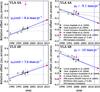 |
Fig. A.1 Revised proper motions of VLA4A and VLA4B. This figure is identical to Fig. 2 of CG08 with additional data. Reference positions are 03:29:03.732 31:16:03.974 (J2000) for VLA4A, and 03:29:03.7566 31:16:04.000 (J2000) for VLA4B. Dotted gray lines display CG08 proper motions based on their measurements (gray points). Solid blue lines are our best linear fit to all VLA radio data including the positions of Tobin et al. (2016). Vertical blue dashed lines identify the weighted date of CALYPSO observations (2012.43). |
Previous and revised proper motions.
Published proper motions for VLA4A and VLA4B were obtained by Carrasco-González et al. (2008, hereafter CG08) from 3.6 cm observations covering the period 1989-2000. Figure A.1 shows that they do not extrapolate exactly to more recent 8−10 mm positions of Tobin et al. (2016), which have a stronger contribution from circumstellar dust making them more relevant for comparison with 1.4 mm CALYPSO data. Figure A.1 shows no evidence for differing proper motions between 3.6 cm (pure free-free emission) and λ ≤ 10 mm where dust contributes. Indeed, the position of the 3.6 cm and 7 mm observations are in agreement within 20 mas (as shown by Anglada et al. 2004), which is fully compatible with the PdBI astrometric precision. We therefore computed revised proper motions by a linear fit to all VLA radio data (see Fig. A.1). The new values agree better with the average proper motion of VLA sources in the NGC1333 region (see Table A.1). We deduced the positions at CALYPSO epoch (2012.43) to be: (03:29:03.7416, +31:16:03.812) for VLA4A and (03:29:03.7648, +31:16:03.834) for VLA4B (J2000). Using only data at λ ≤ 10 mm for proper motions would not significantly change our results.
Appendix B: Source of the NIR continuum and jet
As noted by HC14, the NIR position measured by 2MASS in 1999 better agrees with VLA4B than VLA4A (Fig. A.1), hence VLA4B is the source of the ≃1990 outburst. Assuming that the dominant source in the NIR remained the same in 2011−2013 as in 1999, HC14 concluded that VLA4B was also the source of the [FeII] jet and H2 outflow features (reproduced and sketched in Fig. C.1). However, given the intrinsic variability of young stars and the fact that VLA4B is in decline phase, one cannot totally exclude VLA4A as the dominant NIR source in 2012. Our CALYPSO data have sufficient angular resolution, sensitivity, and astrometric quality provides and independent way of checking this. This test is shown in Fig. B.1 on a single channel map. The morphology of the CO, SiO, and SO emission shows a systematic shift from H2 features when the NIR source is registered on VLA4A (top row of Fig. B.1), whereas they match very well when the NIR source is registered on VLA4B (bottom row of Fig. B.1). This good match is also seen in other individual channel maps in Appendix D, and in the integrated velocity ranges in Fig. 2. Implications are discussed in Sect. 3.2.
 |
Fig. B.1 Channel maps of CO, SiO and SO at VLSR = − 92.15 km s-1 (blue contours) with the positions of the [FeII] jet (green segment), H2 inner bubble, arcs and vertical linear feature (in red) from HC14 superimposed. The NIR source was assumed to be either VLA4A (top row) or VLA4B (bottom row). The latter is unambiguously favored. |
Appendix C: Wiggling models for the CO/H2 jet
 |
Fig. C.1 Figure 4 of HC14 registered on VLA4B, with their main H2 features outlined in dashed white: inner “bubble” (denoted (a)), outer arcs (denoted (b) and (c)), and the fainter “linear feature” joining (a) and (b). A cross denotes the SiO EHV peak ahead of arc (c). Coloured curves show our best wiggling models in three scenarios (see Table C.1 for details). Predicted companion positions in the orbital models are displayed by filled circles of same color. The [FeII] jet from VLA4B (cf. HC14) is shown as a short black segment. |
We computed simple ballistic models of CO/H2 jet wiggling in three scenarios : (1) orbital motion of VLA4B as the CO jet source, (2) orbital motion of a (so far unseen) companion of VLA4B as the CO jet source, (3) precessing jet from VLA4B. We used the equations of Masciadri & Raga (2002), where we added projection effects at small view angles. We explored a grid of parameters to find the smallest mean χ2 deviation from the H2 linear feature, the apex of arc (b), and the EHV SiO peak ahead of arc (c) (see Fig. C.1). The CO EHV jet at 4′′ to 6′′ was not used as a constraint in the χ2, as numerical simulations show increased deviations from ballistic trajectories beyond the first wiggle wavelength (Masciadri & Raga 2002), but it was used to constrain the wiggling period. Given the complex “loop” effects at small view angle, the temporal variation of jet velocity could not be inverted separately from the trajectory like for edge-on systems. Since a global inversion procedure lies well beyond the scope of this Letter, we approximated the CO jet velocity variations by a simple piece-wise model, with Vjet = VLSR − Vsys = − 98.5 km s-1 out to ≃3′′, and Vjet = − 123.5 km s-1 from 4 to 6′′, based on Fig. 3 and discussion in Sect. 3.2. To restrict parameter space, we fixed i = 20° and considered only circular orbits perpendicular to the jet axis (for the orbital case).
We could find a good match to the observed H2/CO jet wiggling in each of the three scenarios. Our best models are plotted in Fig. C.1 on top of the H2 jet features from Fig. 4 of HC14, and in Fig. 4 on top of the CO and SiO EHV integrated maps. The good match, despite our simplifying assumptions, suggests that they should not be too far from the actual solution. The corresponding parameters are listed in Table C.1.
We checked a posteriori if the [Fe II] micro-jet extending 0.3′′ from VLA4B at PA = 145° (HC14, black segment in Fig. C.1) is consistent with our models. We find that our jet models arising from VLA4B automatically reproduce it to within a few degrees (green and orange in Fig. C.1, where we took Vjet = − 148.5 km s-1 within 0.3′′, cf. HC14). Alternatively, when the H2/CO jet comes from a companion, our best model (see red curve in Fig. C.1) intersects in projection the [FeII] jet near the center of inner H2 bubble (a). Both the H2 bubble and the sudden disappearance of the [Fe II] jet might then result from jet collision. In conclusion, the [Fe II] jet coming from VLA4B appears consistent with all three scenarios.
Orbital models of CO jet wiggling clearly require a closer (so far unseen) companion to VLA4B than VLA4A. A separation of 70 au (i.e., VLA4A) with an orbital period ≃93 yr would imply a total mass Mtot ≃ 7 − 35 M⊙ (for eccentricity e = 0.8 − 0) that is clearly excluded. This directly stems from Kepler’s third law Mtot/M⊙ = (a/au)3 (τo/yr)-2 with a semi-major axis a ≥ D/ (1 + e). The second part of Table C.1 lists the constraints on binary separation and individual masses for a more realistic Mtot< 4 M⊙ (compatible with the observed luminosity) and a minimum CO jet source mass MCOjet ≥ 0.1 M⊙. A companion separation 20–32 au is needed, and the CO jet source would be the less massive. The predicted companion positions are shown in Fig. C.1.
If CO jet wiggling is instead due to jet precession, the current popular interpretation proposed by Terquem et al. (1999) is that it results from inner disk precession induced by a companion on an inclined orbit. In the case of rigid precession of a uniform disk, truncated at R ≃ a/ 3, Eq. (1) of Terquem et al. (1999) relates the precession period τp to the orbital period as τo =  with μ = M2/Mtot. For a realistic CO jet source mass 0.1 ≤ MCOjet/M⊙ ≤ 2, with orbital velocity Vo ≤ 1.2km s-1 (orbital wiggles ≤ 2°) we infer a planet-mass companion at ≤0.5 au (see Table C.1). However, a disk truncated at 0.15 au seems unlikely to produce a bright CO jet. The condition for rigid precession (Terquem et al. 1999) translates here as (R/ au)3 / 2 < (H/ 0.01R)(τp/ 100yr)(MCOjet/M⊙)1 / 2, with H the scale height. Hence, non-rigid precession of a larger disk induced e.g. by VLA4A cannot be excluded, by lack of predictions in this regime.
Best models for i = 20° and inferred source properties.
Appendix D: Channel maps of CO, SiO, and SO
 |
Fig. D.1 CO(2–1) channel maps over the same field of view as in Fig. 2 with H2 features from HC14 drawn in red, and PA = 155° shown as a black line of length 5′′. Red and black crosses show VLA4B (east) and VLA4A (west), respectively. |
 |
Fig. D.2 SiO(5–4) channel maps over the same field of view as in Fig. 2 with H2 features from HC14 drawn in red, and PA = 155° shown as a black line of length 5′′. Red and black crosses show VLA4B (east) and VLA4A (west), respectively. Complex organic molecules present in this range are identified by red labels in their central emission channel (from Belloche et al., in prep.). |
 |
Fig. D.3 SO(65 − 54) channel maps over the same field of view as in Fig. 2 with H2 features from HC14 drawn in red, and PA = 155° shown as a black line of length 5′′. Red and black crosses show VLA4B (east) and VLA4A (west), respectively. Complex organic molecules present in this range are identified by red labels in their central emission channel (from Belloche et al., in prep.). |
All Tables
All Figures
|
Fig. 1 Top: 1.4 mm continuum maps of SVS13 A using A configuration (left) and A+C (right). Contours start at 3σ and 10σ respectively, and increase by 10σ. Crosses show the positions of VLA4B and VLA4A, corrected for our proper motions (Appendix A). The synthesized beam is plotted in the bottom left corner. Bottom: residuals after removal of a point source fit to the A config. uv-data at the position of VLA4A. The color scale is in mJy/beam. |
| In the text | |
|
Fig. 2 Maps of CO, SiO and SO integrated over three VLSR ranges: EHV = –150 to –68 km s-1, IHV = –68 to –28 km s-1, SHV = –28 to − 3 km s-1. Red and black crosses denote VLA4B and VLA4A, respectively. The compact emission peaked on VLA4A is entirely due to COMs (identified in Figs. D.2 and D.3). The bottom right panel shows Fig. 4 of HC14 registered on VLA4B. Their main H2 features are outlined in white (cf. text and expanded view in Fig. C.1). They are reported in red in the other panels. The black line displays PA = 155° (B00). |
| In the text | |
|
Fig. 3 PV diagrams along PA = 155°. Dashed lines indicate the reference position (VLA 4B) and the systemic velocity Vsys = 8.5 km s-1 (from SO). Contours start at 3σ with steps of 14σ for SiO(5–4), 7σ for SO(65 − 54) and 21σ for CO(2–1). The color scale displays the intensity in K. Vertical dotted lines indicate the position of the H2 features of HC14 as labeled in Fig. 2. Red and black crosses show velocities for which the molecules peak on arcs (b) and (c), respectively. The orange arrows indicate contamination by complex organic molecules (COMs). |
| In the text | |
|
Fig. 4 Left panels: centroid velocity (color) and integrated intensity (contours) in CO(2–1) EHV a) and SiO(5–4) EHV+IHV c). Best fit wiggling models are overplotted in red, orange, and green (see Appendix C for details). Right panels: transverse PV diagrams of CO(2–1) b) and SiO(5–4) d) at the three distances indicated in each sub-panel, and perpendicular to mean PA = 155°. Red lines are visual cues. |
| In the text | |
|
Fig. 5 Wide field CO maps of the SVS 13A outflow corrected from primary beam attenuation, in three velocity ranges: blue: EHV (− 150 to − 68 km s-1), green: IHV (− 68 to − 28 km s-1), red: Sred (+10 to +40 km s-1). The three arrows show the directions of the three jets: to HH11 (PA = 133°, pink), the wiggling H2/CO jet (PA = 155 ± 10°, solid and dashed blue lines) and the third jet suggested by velocity sign reversal (PA ≃ 0°, gray). The pink cross shows the SiO/SO knot X at –28 km s-1. Pink contours show HH11 extension (Noriega-Crespo & Garnavich 2001). Dotted black contours outline the EHV Bullet 2 as mapped by B00. Dashed segment shows where Chen et al. (2016) reported possible rotation. VLA4A/4B are indicated as yellow crosses. |
| In the text | |
|
Fig. A.1 Revised proper motions of VLA4A and VLA4B. This figure is identical to Fig. 2 of CG08 with additional data. Reference positions are 03:29:03.732 31:16:03.974 (J2000) for VLA4A, and 03:29:03.7566 31:16:04.000 (J2000) for VLA4B. Dotted gray lines display CG08 proper motions based on their measurements (gray points). Solid blue lines are our best linear fit to all VLA radio data including the positions of Tobin et al. (2016). Vertical blue dashed lines identify the weighted date of CALYPSO observations (2012.43). |
| In the text | |
|
Fig. B.1 Channel maps of CO, SiO and SO at VLSR = − 92.15 km s-1 (blue contours) with the positions of the [FeII] jet (green segment), H2 inner bubble, arcs and vertical linear feature (in red) from HC14 superimposed. The NIR source was assumed to be either VLA4A (top row) or VLA4B (bottom row). The latter is unambiguously favored. |
| In the text | |
|
Fig. C.1 Figure 4 of HC14 registered on VLA4B, with their main H2 features outlined in dashed white: inner “bubble” (denoted (a)), outer arcs (denoted (b) and (c)), and the fainter “linear feature” joining (a) and (b). A cross denotes the SiO EHV peak ahead of arc (c). Coloured curves show our best wiggling models in three scenarios (see Table C.1 for details). Predicted companion positions in the orbital models are displayed by filled circles of same color. The [FeII] jet from VLA4B (cf. HC14) is shown as a short black segment. |
| In the text | |
|
Fig. D.1 CO(2–1) channel maps over the same field of view as in Fig. 2 with H2 features from HC14 drawn in red, and PA = 155° shown as a black line of length 5′′. Red and black crosses show VLA4B (east) and VLA4A (west), respectively. |
| In the text | |
|
Fig. D.2 SiO(5–4) channel maps over the same field of view as in Fig. 2 with H2 features from HC14 drawn in red, and PA = 155° shown as a black line of length 5′′. Red and black crosses show VLA4B (east) and VLA4A (west), respectively. Complex organic molecules present in this range are identified by red labels in their central emission channel (from Belloche et al., in prep.). |
| In the text | |
|
Fig. D.3 SO(65 − 54) channel maps over the same field of view as in Fig. 2 with H2 features from HC14 drawn in red, and PA = 155° shown as a black line of length 5′′. Red and black crosses show VLA4B (east) and VLA4A (west), respectively. Complex organic molecules present in this range are identified by red labels in their central emission channel (from Belloche et al., in prep.). |
| In the text | |
Current usage metrics show cumulative count of Article Views (full-text article views including HTML views, PDF and ePub downloads, according to the available data) and Abstracts Views on Vision4Press platform.
Data correspond to usage on the plateform after 2015. The current usage metrics is available 48-96 hours after online publication and is updated daily on week days.
Initial download of the metrics may take a while.