Fig. C.1
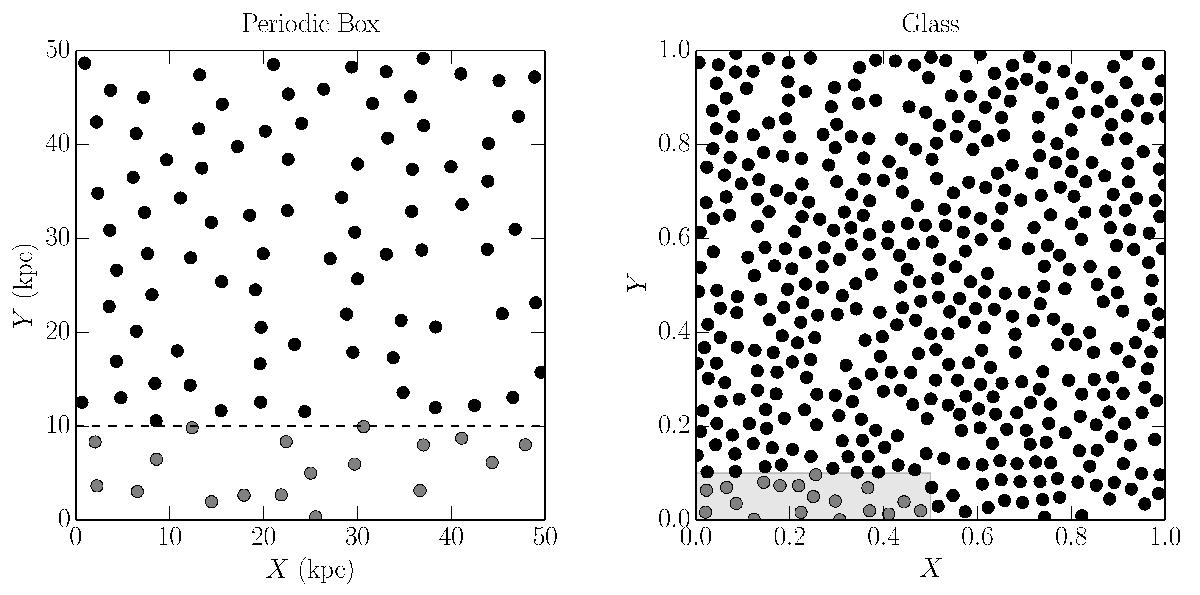
Particle creation schematic. The periodic box is shown in the left panel. The SPH glass is shown on the right. When particles need to be created (below the dashed line), a region of the SPH glass is selected (right panel, grey shading) according to Eq. (C.1). The positions of the particles within this region is then scaled to match the boundaries of the particle creation region, resulting in the grey points. The velocity of the particles is then set according to Eq. (12), and the other properties based on the assumed halo profile. At the next time step, the region of glass selected would start at the top of the shaded region (0.1 in the right-hand box) repeating the glass in any dimension when necessary.
Current usage metrics show cumulative count of Article Views (full-text article views including HTML views, PDF and ePub downloads, according to the available data) and Abstracts Views on Vision4Press platform.
Data correspond to usage on the plateform after 2015. The current usage metrics is available 48-96 hours after online publication and is updated daily on week days.
Initial download of the metrics may take a while.