Fig. 5
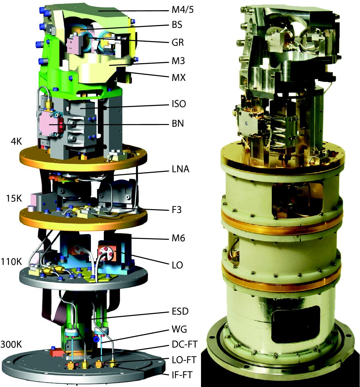
CAD drawing (with the fiberglass spacer rings omitted) and photograph of the assembled receiver. The optics assembly contains the top part (M4/5), bottom part (M3), beam splitter (BS), polarizing grid (GR) and the mixers (MX). Further down on the 4 K level are the bias network boxes (BN), isolators (ISO), and LNAs (LNA). On the 15 K level are the LO infrared blocking filters (F3). The 110 K level contains the LO multipliers (LO) with associated mirrors (M6). Finally, on the 300 K level (the vacuum flange) reside the ESD protection board (ESD) on top of the DC feedthroughs (DC-FT), and the LO feedthroughs (LO-FT) and IF feedthroughs (IF-FT). The LO waveguide (WG) contains a stainless-steel thermal break.
Current usage metrics show cumulative count of Article Views (full-text article views including HTML views, PDF and ePub downloads, according to the available data) and Abstracts Views on Vision4Press platform.
Data correspond to usage on the plateform after 2015. The current usage metrics is available 48-96 hours after online publication and is updated daily on week days.
Initial download of the metrics may take a while.