Fig. 2
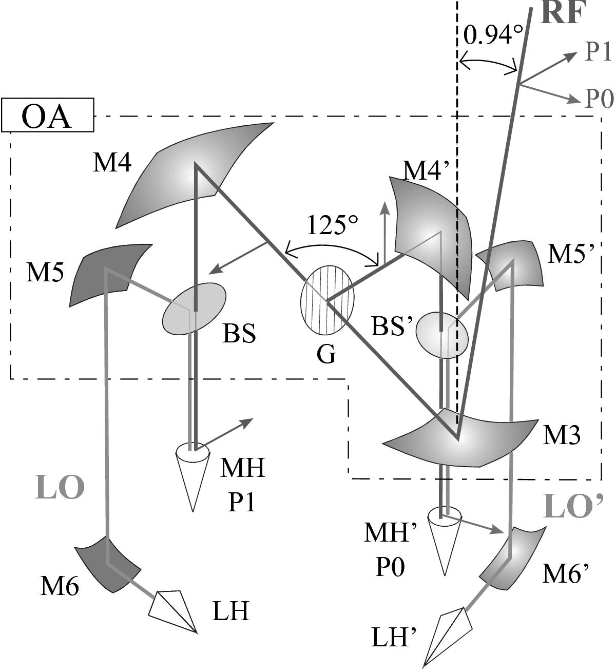
Layout of the optical system for focusing the RF beam and injecting the LO signals. The RF beam coming from the telescope hits the first in-vacuo mirror, M3. Then, the beam reaches a polarizing grid, G, where it is divided in its two linear-polarization components, P0 and P1. We consider here the P1 path only; the P0 path is identical, but with all component labels primed. After the polarizer, the beam hits a second mirror M4 that completes the focusing of the beam into the mixer horn MH. In front of the mixer horn there is a 5% reflective beam splitter BS, used to insert the LO beam that is formed by the LO horn, LH, on the 110 K level, and subsequently focused by the two LO mirrors M6 and M5, into the mixer horn. All mirrors are off-axis ellipsoids. Since the cartridge is located off the main telescope axis, the incoming RF beam has to form an angle of 0.94° with respect to the cartridge axis. The components inside the dashed polygon form the optics assembly (OA), situated entirely at the 4 K level. The optics assembly also contains two beam dumps (not shown here) that absorb the radiation from the LO source that is transmitted through the beam splitters, and one that terminates the unused fourth “port” of the polarizer.
Current usage metrics show cumulative count of Article Views (full-text article views including HTML views, PDF and ePub downloads, according to the available data) and Abstracts Views on Vision4Press platform.
Data correspond to usage on the plateform after 2015. The current usage metrics is available 48-96 hours after online publication and is updated daily on week days.
Initial download of the metrics may take a while.