| Issue |
A&A
Volume 574, February 2015
|
|
|---|---|---|
| Article Number | A95 | |
| Number of page(s) | 8 | |
| Section | The Sun | |
| DOI | https://doi.org/10.1051/0004-6361/201424880 | |
| Published online | 30 January 2015 | |
Centre-to-limb properties of small, photospheric quiet-Sun jets
1 Max-Planck-Institut für Sonnensystemforschung, Justus-von-Liebig-Weg 3, 37077 Göttingen, Germany
e-mail: This email address is being protected from spambots. You need JavaScript enabled to view it.
2 School of Space Research, Kyung Hee University, Yongin, Gyeonggi-Do, 446-701, Korea
3 National Solar Observatory (NSO), Boulder, CO 80303, USA
Received: 29 August 2014
Accepted: 17 December 2014
Abstract
Context. Strongly Doppler-shifted Stokes V profiles have been detected in the quiet Sun with the IMaX instrument on-board the SUNRISE stratospheric balloon-borne telescope. High velocities are required to produce such signals, hence these events have been interpreted as jets, although other sources are also possible.
Aims. We aim to characterize the variation of the main properties of these events (occurrence rate, lifetime, size, and velocities) with their position on the solar disk between disk centre and the solar limb.
Methods. These events were identified in SUNRISE/IMaX data according to the same objective criteria at all available positions on the solar disk. Their properties were determined using standard techniques.
Results. Our study yielded a number of new insights into this phenomenon. Most importantly, the number density of these events is independent of the heliocentric angle, meaning that the investigated supersonic flows are nearly isotropically distributed. Size and lifetime are also nearly independent of the heliocentric angle, while their intensity contrast increases towards the solar limb. The Stokes V jets are associated with upflow velocities deduced from Stokes I, which are stronger towards the limb. Their intensity decreases with time, while their line-of-sight velocity does not display a clear temporal evolution. Their association with linear polarization signals decreases towards the limb.
Conclusions. The density of events appears to be independent of heliocentric angle, establishing that they are directed nearly randomly. If these events are jets triggered by magnetic reconnection between emerging magnetic flux and the ambient field, then our results suggest that there is no preferred geometry for the reconnection process.
Key words: Sun: activity / Sun: magnetic fields / Sun: photosphere / Sun: granulation
Now at Department of Physics, Stanford University, Stanford, Ca 94305, USA.
© ESO, 2015
1. Introduction
The improvement of the spatial resolution of solar observations over the past decades has led to the detection of a number of exciting small-scale features. Observations made in the absence of seeing effects have been particularly valuable. Thus the Hinode mission (Kosugi et al. 2007; Tsuneta et al. 2008), with its high spatial resolution (0.3′′) full Stokes vector data, has contributed very significantly to the study of the magnetism of the quiet Sun. The SUNRISE mission, during its first science flight (see Barthol et al. 2011; Solanki et al. 2010), has allowed us to probe the quiet Sun in even greater detail with seeing-free data, thanks to its even higher resolution of 0.15′′.
Data sets.
Number of jets found at the four investigated μ positions.
It allowed, among many other results, kG magnetic fields to be resolved (Lagg et al. 2010); the brightness contrasts of small magnetic elements to be measured in the UV (Riethmüller et al. 2010), which is of importance for solar irradiance variations (Solanki et al. 2013); the dynamics of horizontal internetwork fields to be followed (Danilovic et al. 2010a), and the internal structure of network magnetic elements to be determined (Martínez González et al. 2012). A surprising discovery was made by Borrero et al. (2010), who found strong circular polarization signals at a wavelength sampling the continuum, which is most naturally interpreted in terms of high upflow or downflow velocities, the former velocities produced by the Doppler shift of the neighbouring Fe i 5250.6 Å into the continuum wavelength. Such signals are short lived and typically last shorter than 2 min. Martínez Pillet et al. (2011b) compared the SUNRISE results with observations from Hinode/SP, finding highly asymmetric and shifted Stokes V profiles. They found that 72% of the features were found at the centre or edge of a granule.
A possible scenario might be that the strong line shifts are produced by magnetic reconnection between a pre-existing field in the intergranular region and an emerging field (Quintero Noda et al. 2013). The 3D magnetohydrodynamic (MHD) simulations of Danilovic et al. (2015) confirmed that the emergence of magnetic flux and its interaction with existing field probably qualitatively reproduces the observational signatures. In some of the cases, these are indeed due to reconnection, but many of the supersonic flows (downflows) are due to convective collapse (e.g., Parker 1978; Nagata et al. 2008; Danilovic et al. 2010b). In addition, Borrero et al. (2010) proposed that the circular polarization signal of a minority (around 20%) of the supersonic magnetic flows that appear in evolving granules might be associated with an exploding granule (Rast 1995).
In this paper, we characterize the centre-to-limb variations (CLV) of the main properties of these features visible in the continuum wavelength filter position of the Stokes V signal. For brevity and consistency with the previous work (Borrero et al. 2010), hereafter we call them jets, although their actual physical interpretation may be more diverse. Such an investigation may allow us to set constraints on the geometry of the magnetic configuration. We use Stokes parameters acquired by the IMaX instrument on-board SUNRISE during its 2009 flight at different distances from the solar limb.
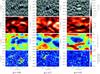 |
Fig. 1 Examples of jets detected in Stokes Vc images at μ = 0.99 (leftmost panels), μ = 0.76 (middle row of panels) and μ = 0.42 (rightmost panels). From top to bottom the panels depict the continuum circular polarization normalized to the averaged quiet-Sun continuum intensity (Vc/Iqs), the continuum intensity normalized to the quiet-Sun average (Ic/Iqs), the LOS velocity, and the linear polarization averaged spectrally over the Fe i 5250.2 Å line. The contours outline | Vc | > | 1.25× 10⁻² | Ic, where the blue contours (red in the lower two rows) signify negative values and the green contours positive values. |
2. Observations and identification of jets
2.1. Observations
The SUNRISE balloon-borne solar observatory was launched on its first science flight on 8th June 2009 (Solanki et al. 2010; Barthol et al. 2011; Berkefeld et al. 2011), carrying two instruments: SuFI (SUNRISE Filter Imager, Gandorfer et al. 2011), a UV filter imager, and IMaX (Imaging Magnetograph eXperiment, Martínez Pillet et al. 2011a), an imaging vector polarimeter operating in Fe i 5250.2 Å. IMaX has a spectral resolution of 85 mÅ, and the effective field of view after phase diversity reconstruction is 45 × 45 arcsec2. The images have a plate scale of 0.055 arcsec pixel-1.
For the sequences used in this study, the IMaX instrument operated in its V5-6 mode, meaning that it recorded the full Stokes vector at five offsets from the centre of the Fe i line (λ0 = 5250.217 Å): ±40 mÅ, ±80 mÅ, and +227 mÅ. We refer to the +227 mÅ offset as the continuum wavelength position (λc) in this paper. In this mode the cadence reached by the instrument is 33 s, the noise level in the reconstructed data is 3−4 ×10⁻³ of the continuum intensity, Ic, at solar disk centre thanks to the six integrations carried out at each wavelength position.
2.2. Data selection
We used the data sets listed in Table 1, recorded on 10th and 13th June 2009. We selected them according to μ = cos θ, and the quality of the time series estimated from the root-mean-square (RMS) contrast of the continuum intensity images.
The data series taken at cosines of the heliocentrinc angle μ≥0.98 were grouped together for this study to enhance the statistics, as have the data series taken at μ=0.46, 0.42 and 0.40, so that we distinguish between four mean μ values. These are given in the first column of Table 2.
The data at μ= 0.76 present fewer events than the rest of the data series, therefore the statistics for this data set are lower. As a consequence, this may affect the main properties such as lifetime, contrast, or area, which may differ from the rest of the data sets.
Borrero et al. (2010) used two data sets of 22.7 and 31.6 min recorded on 9 June, both probably close to solar disk centre. We did not use these data series in our study because the estimation of the heliocentric angle for these data is not as precise as of the data sets used here.
To precisely calculate the pointing of the telescope taken after 10th June 2009 at 07:47 UT, we used the images in which the limb is visible. These were obtained as part of dedicated limb-to-limb scans with exactly this purpose in mind. We fitted the solar limb to a circle of the radius of the Sun at that time and obtained the centre of the Sun in arcsec. That allowed us to estimate the offset with respect to the imprecise values given in the header of the images. The obtained (x,y) offsets were (70.9 ± 10.0, −69.3 ± 9.6) arcsec.
2.3. Identification of the jets at Stokes Vc
Following the same procedure as Borrero et al. (2010), we identified all features with an unsigned Stokes V signal, conservatively taken to be | 1.25 × 10⁻² | Ic, corresponding to 3−4σ at the continuum wavelength, that is, data reconstructed in Vc – taking into account the phase-diversity calibration of the point-spread function of the optical system. To avoid false positives due to noise spikes etc., we also applied a size threshold of 9 pixels, which roughly corresponds to the spatial resolution of the data. Any feature fulfilling these criteria is called a jet from now on, for the sake of a clear nomenclature. After events were identified on individual frames, we grouped those that displayed a spatial overlap of at least one pixel on sucesive frames, assigning them to the same jet. We allowed for a temporary drop in the signal level of an event, which can be caused by noise, since a signal slightly above 3σ at one point can fall below the threshold at another time. Thus we assigned features that overlapped in position, but lay on frames with a temporal gap of up to 66 s (two frames) to the same jet. Table 2 lists the jets investigated in the four μ regimes. The third column gives the total number of events found; the fourth column the total number of jets after Vc features on different frames have been grouped and the fifth column refers to the number of events, already grouped, that have lifetimes T longer than 33 s, finding that on average 66% of events live shorter than 33 s.
The ratio between the number of individual features and jets is not affected by the position of the events on the solar disk, which suggests that the lifetimes of jets seen at different positions on the solar disk is roughly the same; see Sect. 3.2.
Jets whose time of appearance or disappearance is unknown were not investigated further.
Figure 1 illustrates jets detected at three μ values. The first row shows Stokes Vc maps. The contours outline areas with | Vc | > | 1.25 × 10⁻² | Ic. The other rows allow determining the continuum intensity, line-of-sight (LOS) velocity, and linear polarization associated with these jets. The variation of the properties of such jets with μ is studied in the next section.
3. Results: jet properties
In this section we concentrate on the CLV of the main properties of the jets with lifetimes equal to or longer than 66 s (two frames). Table 3 lists the number density of jets per minute and arcsec, their average lifetimes, areas, and continuum contrast in the four μ bins. The listed areas, intensity contrast, and LOS velocities are mean values (averaged over all events) of the maximum area reached by each event, and the estimated error equals the mean standard deviation divided by the square-root of the number of jets. Below we present the results in greater detail.
Main properties of the jets in the four μ bins.
3.1. Morphology
In some cases, the Stokes Vc signal displays positive and negative values at the same time and located spatially close together. An example is shown in the right column of Fig. 1. From studying a sample of twenty jets for each μ bin, we found no evidence of a trend in the occurrence of bipolar magnetic features with μ. Typically, only 1−2 of the 20 jets from the sample have a bipolar Vc signal.
The normalized continuum intensity maps (Ic/Iqs) in the second row of Fig. 1 indicate that the jets tend to occur at the edges of granules. This trend is confirmed for all heliocentric values (e.g. Fig. 1) for a sample of 20 randomly chosen events in each μ bin, although a minority (≈20%) appear to be located in intergranular lanes. Their evolution in time shows that the events appear at the borders of splitting (exploding) granules.
3.2. Number density and lifetime of the jets
The average number density of events, given in Table 3, is similar to the one estimated by Borrero et al. (2010) (7.6 × 10⁻⁴ events per minute per arcsec2), within a 1σ error, irrespective of the value of μ. This indicates that the jets point in all directions nearly equally, although there may be fewer that point close to the horizontal direction (note that μ = 0.42 corresponds to a heliocentric angle θ of 65.2°).
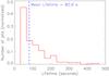 |
Fig. 2 Lifetime histogram combining results from all four μ bins. The event density has been normalized to 1 and jets found in only one frame are not displayed here. |
Lifetime distributions and average lifetimes of the jets were determined for each μ bin. Since no significant differences were discovered between the four heliocentric-angle bins, a single lifetime distribution with better statistics was calculated by combining values from all μ bins.
Figure 2 shows this combined lifetime histogram after removing the jets seen in just a single frame. The average duration of the jets is 80.9 s, very similar to the value estimated by Borrero et al. (2010) (81.3 s). Assuming that the density of events follows a power-law behaviour (y = axb), the power-law index, b, has a value of −1.96. A value so close to −2 implies that the jets seen on any given snapshot are equally likely to be short-lived as long-lived. This is because although there are many more short-lived jets, the fewer longer lived ones appear in multiple frames. At a power law of −2, both groups are equally represented in a given frame. The fact that nearly half of the jets are seen in just one frame suggests that there are probably many jets with shorter lifetimes that have not been detected. Roughly 9% of the jets are visible for longer than 3 min.
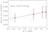 |
Fig. 3 Centre-to-limb variation of the jet areas (at the time at which their area is largest). Each symbol represents the average over all jets within a given μ-bin. The error bars represent the standard deviations divided by the square-root of the number of jets. The solid line and the text in the figure refer to a linear regression. |
3.3. Jet area
The averages of the maximum jet areas decrease towards the solar limb by less than 11%. Note that the decrease with μ is much slower than μ, so that it is not commensurate with the foreshortening of a horizontal surface. This reduction in area with μ lies within the error bars, so that it cannot be ruled out that the jets have the same average area at all μ.
The histograms of the maximum projected area covered by the jets for all four μ bins are rather similar. Based on the relatively weak dependance on μ, we took all the jets together and plot a single histogram in Fig. 4, which has significantly improved statistics. The histogram of the maximum jet area of the jets peaks next to the detection threshold of 0.027 arcsec2. This implies that there are probably many undetected events at smaller spatial scales. By fitting the distribution to a polynomial function on a logarithmic scale, the estimated power-law index of −2.31 shows that there is no clear conclusive behaviour of the trend of the area of the jets since the variation of the averaged area with μ varies within the standard deviation error. As in the previous section, having a power law of −2 would mean that small jets cover the same area in a given frame as large jets. The obtained power law of −2.31 implies that smaller jets cover a much larger area than the large jets. Furthermore, the fact that more than 43% of the jets are smaller than 0.027 arcsec2 suggests that there are probably many smaller jets that have not been detected.
This result is compatible with the findings of Danilovic et al. (2015) that most of the events retrieved from MHD simulations were on average considerably smaller than the observed events. This might also imply that a decrease in the size of the events towards the limb may be partly masked by the fact that so many events have areas close to the spatial resolution limit.
The average of the maximum areas is about 0.057 arcsec2, 1.2 times higher than the one reported by Borrero et al. (2010), but it should be noted that Borrero et al. (2010) considered instantaneous areas of the jets and not only the maximum areas reached by the jets during their evolution.
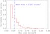 |
Fig. 4 Histogram of maximum area reached by each jet for all studied positions on the solar disk. The area density has been normalized to 1 by dividing by the total number of jets. Only jets with areas larger than 0.027 arcsec2 are displayed. |
3.4. Intensity contrast
The intensity contrast was defined as  , where Iqs is the averaged continuum intensity of the quiet-Sun image and Ic is the continuum intensity averaged over all spatial pixels covered by the jet. We plot in Fig. 5 the intensity contrast averaged over all jets in a certain μ bin, with the contrast for a particular jet being taken at the time step at which its surface area is largest. The contrast increases towards the limb, as can be seen from Fig. 5 (Table 3). A similar behaviour is found if the contrasts at each time step during the lifetime of a jet are considered.
The contrast value resulted at ⟨ μ ⟩=0.76 is well above the linear fit shown in Fig. 5. Since the represented error bars are the standard deviations divided by the square-root of the number of jet and considering that at ⟨ μ ⟩=0.76 there are fewer jets than for the rest of the data sets, the value is within the expected behaviour.
While the contrast increases towards the limb, the full width at half maximum of the distribution becomes slightly narrower, being 0.25 units at ⟨ μ = 0.99 ⟩ and 0.23 for at ⟨ μ = 0.42 ⟩. The percentage of events with an intensity exceeding the averaged quiet-Sun intensity increases from 63% at ⟨ μ ⟩=0.99 to 93% at ⟨ μ ⟩=0.42.
The excess brightness of the jets is related to the fact that most of the events occur at the bright edges of the granules. The increased contrast near the limb may be related to the enhanced brightness of granule edges near the limb. Alternatively, it may be related to the origin of these events, particularly if they are associated with the convective collapse, since magnetic features tend to display higher contrasts near the limb (e.g., Solanki 1993; Carlsson et al. 2004; Keller et al. 2004), although this observation cannot rule out effects due to reconnection as the cause (Quintero Noda et al. 2013).
We also found that jets smaller in size have higher contrast values than the larger ones. The slope from the linear fit (−0.15 ± 0.07) is significant at the 2σ level.
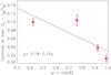 |
Fig. 5 Same as Fig. 3, but for the intensity contrast (defined as |
3.5. Line-of-sight velocity
The LOS velocity was calculated by fitting a Gaussian profile to the four wavelength points sampling the Fe i line (±40 and ±80 mÅ relative to 5250.217 Å) and correcting for the convection, solar rotation (see Balthasar 1984), and shifts caused by the instrumental configuration. The CLV of wavelength shift introduced by the granulation was compensated for by using the results of Balthasar et al. (1985). According to these, the convective blueshift decreases by 140 m s-1 between μ = 0.99 and 0.42. Note that the LOS velocities reported there were obtained from the Stokes I profile.
From considering the jets at the moment at which their area is largest, we found that the jets are associated with strong upflow velocities (negative values according to our reference system). This is one of the most universal characteristics, as can be judged from Fig. 6 (cf. third row of Fig. 1), which depicts histograms of the LOS velocity of the jets at the time at which their area is largest1. The upflow velocities are somewhat stronger closer to the solar limb, but this difference is not very significant. While 94.1% of the jets are associated with upflows around disk centre, this fraction has fallen to 87.7% at μ = 0.42.
Since the LOS velocity is the combination of a vertical and a horizontal component, stronger velocities for lower heliocentric angles might imply that the horizontal component is somewhat stronger or that the events seen closer to the limb are associated with stronger flows. This could be the case because close to the limb events are seen higher in the atmosphere.
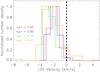 |
Fig. 6 LOS velocity histograms at the four analysed μ bins. The highest number density of events has been normalized to 1. Zero LOS velocity is indicated by the vertical dashed line. |
Although more than 90% of the jets with positive contrast are associated with Stokes I upflows, there is no clear relationship between the continuum intensity and the LOS velocity associated with the jets (correlation coefficient R ≈ 0.3).
3.6. Stokes V signal
Borrero et al. (2010) found that near disk centre most jets are not associated with a significant unshifted Stokes V signal at the event location. To test whether this is true for other μ values, we determined  for each jet at the time that it covered the largest number of spatial pixels, n.
Here i refers to the four wavelength positions in the Fe i 5250.217 Å line and j runs over the spatial pixels covered by the jet.
9.6% of the jets are associated with a magnetic signal >3σ in Fe i 5250.2 Å, with no clear variation between the different heliocentric positions. The same process was repeated for the lower noise IMaX level 1 data, that is, before phase-diversity image reconstruction, and it yielded similar results.
3.7. Relation with linear polarization signal
To study the relation with horizontal magnetic fields, for instance, with emerging magnetic features, we considered the linear polarization signals associated with the jets at different heliocentric angles. The phase-diversity reconstruction process increases the noise by a factor of 3 in the restored Q and U frames. Because the Q and U signals display steep histograms that very rapidly drop with amplitude, we used the Stokes Q and U parameters of the non phase-diversity reconstructed data to derive the linear polarization signal. The signal was calculated for each wavelength point along the Fe i 5250.2 Å and averaged as follows: LP = , where i refers to the wavelength point.
The fourth row in Fig. 1 shows the linear polarization maps, where the contours represent Vc> | 1.25× 10⁻² |Ic.
We identified all features with a signal higher than three times the noise level (LP >2×10⁻³ LPc≈3σ) in the linear polarization images. Only features found in LP with a threshold size greater than 9 pixels were taken into account.
Some of the features seen in LP appear close in time and space to the ones studied in Vc. LP signals within 0.55 arcsec distance of a jet measured in Vc are assumed to be spatially related; linear polarization signals lying farther away are assumed to be unrelated with the event. To temporally associate Vc and LP signals, we assumed that they may be related within a temporal window of 5 frames (Δt = 165 s) between the appearance or disappearance of one of the signals and the appearance or disappearance of the other.
We allowed such a large difference in time between the appearance or disappearance of Vc and LP signals because scenarios with a lapse between these two signals are quite easy to imagine. For instance, fresh flux appears at the solar surface and slowly rises (first appearance of LP) until it reconnects with an already present field (later appearance of jet).
According to Fig. 7, at the centre of the solar disk almost half of the jets are associated with a linear polarization signal. The ratio decreases towards the solar limb, so that at ⟨ μ ⟩ = 0.42 only 11% of the Vc features lie close to a linear polarization signal, although there is much scatter in the plotted relationship. Better statistics are needed to reach a reliable conclusion on this point.
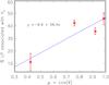 |
Fig. 7 Percentage of jets associated (spatially and temporally) with a linear polarization signal versus μ. The error bars have been calculated taking into account the temporal and spatial uncertainties. |
More than 60% of the LP signals associated with a jet appear before the circular polarization signal for μ ≈ 1 close to the 75% of the jets that Quintero Noda et al. (2013) found using a different technique, while at ⟨ μ ⟩=0.42 less than 35% of the jets have LP emission appearing before Vc. For more than half of these jets (56% at ⟨ μ ⟩=0.99 to 64% at ⟨ μ ⟩=0.42), the LP signal also continues for some time after the disappearance of Vc.
3.8. Jet evolution
We normalized the lifetime of the jets from their appearance to their disappearance. Only jets living for at least three frames were studied at times t = 0.00 (appearance), 0.50, and 1.00 (disappearance), using spline interpolation for the cases in which the lifetime of the jets is equal to or longer than four frames (2 min 12 s).
Figure 8 displays the evolution of intensity contrast (as introduced in Sect. 3.4) over their normalized lifetime, averaged over all jets at a given μ. Colours distinguish between different heliocentric angles. The error bars represent the standard deviations divided by the square-root of the number of jets.
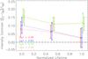 |
Fig. 8 Averaged intensity contrast associated with the jets over their normalized lifetime for different heliocentric angles. We plot averages over all jets in a particular ⟨ μ ⟩ bin at a specific phase of their evolution. The values for the four ⟨ μ ⟩ have been slighly shifted on the x-axis to facilitate visual comparison. The lifetime is normalized to 1. The intensity contrast |
In all the four cases the averaged intensity contrast is highest at the time of the appearance of the jet and decreases with time, but since the uncertainty in the values is similar in magnitude to the trend, no definite conclusion can be drawn. Near the limb the intensity contrast is higher (see Sect. 3.4), and its drop with time is not as steep as close to disk centre.
Similarly, we also considered the evolution of the LOS velocity associated with the jets. No significant trend was found, although there may be a slight tendency for the upflows to increase with time (but only below the 2σ level).
The jet areas were found to peak after roughly half of their lifetime (Fig. 9). Jets near the limb appear to be somewhat smaller early in their life, but this difference is washed out in the course of their evolution.
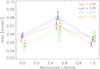 |
Fig. 9 Averaged area of the jets over their normalized lifetime for different heliocentric angles. We plot averages over all jets in a particular ⟨ μ ⟩ bin at a specific phase of their evolution. The values for the four ⟨ μ ⟩ have been slighly shifted on the x-axis to facilitate visual comparison. The lifetime is normalized to 1. The area has been interpolated at different times [t = 0 (appearance), 0.5, and 1 (disappearance)]. |
4. Conclusions
High-speed flows are present in the solar atmosphere at all heights and scales. Early observations at low resolution with Yohkoh revealed large and comparatively rare X-ray jets (Shibata et al. 1994). Later, signatures of bi-directional reconnection jets were detected (Innes et al. 1997). At the higher resolution of Hinode, smaller jets located in the quiet Sun were discovered by Shibata et al. (2007). More recently, even smaller jets were seen by the NST (Goode et al. 2010). To which extent the SUNRISE/IMaX high-speed events studied here and in Borrero et al. (2010) are similar to those detected by Goode et al. (2010) that were analysed in more detail by Yurchyshyn et al. (2011) cannot be fully judged at present. However, the fact that the NST jets emerge from intergranular lanes while the “jets” we studied are associated mainly with bright upflows, as well as other differences, suggests that we are seeing different features.
Possibly the most important finding of this study is that the number density of jets does not vary with the heliocentric angle, meaning that the jets are equally distributed across the solar disk. This implies an almost isotropic distribution of the jet directions. Our estimated number density is similar to that of Borrero et al. (2010), within our 1σ error.
Our lifetime values are consistent with those from Borrero et al. (2010, 80 s) and do not change with μ.
The averaged area covered by a jet decreases slightly towards the solar limb. This gentle decrease is probably the result of foreshortening. The intensity contrast increases towards the solar limb, as does the LOS velocity obtained from the Stokes I profile.
The Stokes Vc signal is associated with a linear polarization signal. The association between horizontal and vertical magnetic fields decreases towards the solar limb. As the reason for this dependence we propose the following: a horizontal magnetic field, as present at the top of a rising loop, gives a weaker linear polarization signal towards the limb, with the decrease in linear polarization being proportional to (1 − μ)2 for a horizontal field directed perpendicular to the nearest limb. This, together with the fact that the most common linear polarization patches lie only slighly above the noise, means that many of them drop below the noise level as their amplitude decreases (see Danilovic et al. 2010a, for the amplitude distribution of linear polarization patches at SUNRISE resolution). This can in principle explain the steep reduction of linear polarization patches associated with Vc jets near the limb seen in Fig. 7.
Danilovic et al. (2013) simulated the reconnection between a pre-existing magnetic field and emerging fluxes resulting in some brightening at the continuum of the line, associated with strong velocities and high temperatures. These results are similar to the reported jets, which reinforces the assumption that they are due to some quiet-Sun reconnection.
The jets can also be associated with the rapid evolution of the granulation at the same location, that is, granules that split or merge at around the time the jets appear. Fast changes in granular flows can be forced by newly emerging magnetic field. This would agree with the scenario proposed by Danilovic et al. (2015). Their MHD simulations showed that the observational signature of high Vc values, that is, the type of phenomena studied here, can be produced when fresh magnetic flux emerges at small scales, mainly due to magnetic reconnection, but also due to convective collapse. However, they did not show whether the signatures also exist at different heliocentric angles.
The jets are associated mainly with upflows with velocities measured in the Stokes I profile of 5250.2 Å higher than 1.5 km s-1 on average. This suggests, but does not prove, that the Vc signal is due to a blueshift contribution of the neighbouring line Fe i 5250.653 Å: the continuum wavelength point λc is situated at +227 mÅ, roughly half way between both lines. Borrero et al. (2013) have inverted L12/2 data from SUNRISE/IMaX (i.e. data at 12 wavelength points, but with higher noise and only with Stokes V information). The inversions suggest that both the LOS velocity and the magnetic polarity change sign along the LOS, which the authors interpret as signatures of magnetic reconnection.
If this interpretation is correct (they do find cases where downflows overlie upflows, which are not easily interpreted in this manner), then the reconnection jets can in principle point in an arbitrary direction, making them consistent with the near-isotropic distribution of events that we found. In addition to reconnection jets, other sources of the high-speed flows found here have been described by Danilovic et al. (2015). They include the rapid emergence of U-loops, produced after subsurface reconnection, and the convective collapse of magnetic fields to kG values (triggered by the emergence of field, but without magnetic reconnection preceding the flow). These processes are also likely to take place, but to what extent they would contribute to the more horizontal supersonic flows still needs to be clarified. Danilovic et al. (2015) also showed that most of the simulated events would remain unresolved in SUNRISE/IMaX data. This indicates the need for even higher resolution observations.
The results do not change when taking into account all the data of the jets at each time step.
Acknowledgments
The German contribution to SUNRISE I was funded by the Bundesministerium für Wirtschaft und Technologie through Deutsches Zentrum für Luft- und Raumfahrt e.V. (DLR), Grant No. 50 OU 0401, and by the Innovationsfond of the President of the Max Planck Society (MPG). The Spanish contribution has been funded by the Spanish MICINN under projects ESP2006-13030-C06 and AYA2009-14105-C06 (including European FEDER funds). The HAO contribution was partly funded through NASA grant number NNX08AH38G. This work was partly supported by the BK21 plus program through the National Research Foundation (NRF) funded by the Ministry of Education of Korea. The authors would like to express particular thanks to Alex Feller for his contribution to the SUNRISE pointing correction.
References
- Balthasar, H. 1984, Sol. Phys., 93, 219 [NASA ADS] [CrossRef] [Google Scholar]
- Balthasar, H., Vázquez, M., & Wöhl, H. 1985, Sterne und Weltraum, 24, 634 [NASA ADS] [Google Scholar]
- Barthol, P., Gandorfer, A., Solanki, S. K., et al. 2011, Sol. Phys., 268, 1 [NASA ADS] [CrossRef] [Google Scholar]
- Berkefeld, T., Schmidt, W., Soltau, D., et al. 2011, Sol. Phys., 268, 103 [NASA ADS] [CrossRef] [Google Scholar]
- Borrero, J. M., Martínez-Pillet, V., Schlichenmaier, R., et al. 2010, ApJ, 723, L144 [NASA ADS] [CrossRef] [Google Scholar]
- Borrero, J. M., Martínez Pillet, V., Schmidt, W., et al. 2013, ApJ, 768, 69 [NASA ADS] [CrossRef] [Google Scholar]
- Carlsson, M., Stein, R. F., Nordlund, Å., & Scharmer, G. B. 2004, ApJ, 610, L137 [NASA ADS] [CrossRef] [Google Scholar]
- Danilovic, S., Beeck, B., Pietarila, A., et al. 2010a, ApJ, 723, L149 [NASA ADS] [CrossRef] [Google Scholar]
- Danilovic, S., Schüssler, M., & Solanki, S. K. 2010b, A&A, 509, A76 [NASA ADS] [CrossRef] [EDP Sciences] [Google Scholar]
- Danilovic, S., Röhrbein, D., Cameron, R. H., & Schüssler, M. 2013, A&A, 550, A118 [NASA ADS] [CrossRef] [EDP Sciences] [Google Scholar]
- Danilovic, S., Cameron, R. H., & Solanki, S. K. 2015, A&A, 574, A28 [NASA ADS] [CrossRef] [EDP Sciences] [Google Scholar]
- Gandorfer, A., Grauf, B., Barthol, P., et al. 2011, Sol. Phys., 268, 35 [NASA ADS] [CrossRef] [Google Scholar]
- Goode, P. R., Yurchyshyn, V., Cao, W., et al. 2010, ApJ, 714, L31 [NASA ADS] [CrossRef] [Google Scholar]
- Innes, D. E., Brekke, P., Germerott, D., & Wilhelm, K. 1997, Sol. Phys., 175, 341 [NASA ADS] [CrossRef] [Google Scholar]
- Keller, C. U., Schüssler, M., Vögler, A., & Zakharov, V. 2004, ApJ, 607, L59 [NASA ADS] [CrossRef] [Google Scholar]
- Kosugi, T., Matsuzaki, K., Sakao, T., et al. 2007, Sol. Phys., 243, 3 [NASA ADS] [CrossRef] [Google Scholar]
- Lagg, A., Solanki, S. K., Riethmüller, T. L., et al. 2010, ApJ, 723, L164 [NASA ADS] [CrossRef] [Google Scholar]
- Martínez Pillet, V., Del Toro Iniesta, J. C., Álvarez-Herrero, A., et al. 2011a, Sol. Phys., 268, 57 [NASA ADS] [CrossRef] [Google Scholar]
- Martínez Pillet, V., Del Toro Iniesta, J. C., & Quintero Noda, C. 2011b, A&A, 530, A111 [NASA ADS] [CrossRef] [EDP Sciences] [Google Scholar]
- Martínez González, M. J., Bellot Rubio, L. R., Solanki, S. K., et al. 2012, ApJ, 758, L40 [NASA ADS] [CrossRef] [Google Scholar]
- Nagata, S., Tsuneta, S., Suematsu, Y., et al. 2008, ApJ, 677, L145 [NASA ADS] [CrossRef] [Google Scholar]
- Parker, E. N. 1978, ApJ, 221, 368 [NASA ADS] [CrossRef] [Google Scholar]
- Quintero Noda, C., Martínez Pillet, V., Borrero, J. M., & Solanki, S. K. 2013, A&A, 558, A30 [NASA ADS] [CrossRef] [EDP Sciences] [Google Scholar]
- Rast, M. P. 1995, ApJ, 443, 863 [NASA ADS] [CrossRef] [Google Scholar]
- Riethmüller, T. L., Solanki, S. K., Martínez Pillet, V., et al. 2010, ApJ, 723, L169 [NASA ADS] [CrossRef] [Google Scholar]
- Shibata, K., Nitta, N., Strong, K. T., et al. 1994, ApJ, 431, L51 [NASA ADS] [CrossRef] [Google Scholar]
- Shibata, K., Nakamura, T., Matsumoto, T., et al. 2007, Science, 318, 1591 [Google Scholar]
- Solanki, S. K. 1993, Space Sci. Rev., 63, 1 [NASA ADS] [CrossRef] [Google Scholar]
- Solanki, S. K., Barthol, P., Danilovic, S., et al. 2010, ApJ, 723, L127 [NASA ADS] [CrossRef] [Google Scholar]
- Solanki, S. K., Krivova, N. A., & Haigh, J. D. 2013, ARA&A, 51, 311 [NASA ADS] [CrossRef] [Google Scholar]
- Tsuneta, S., Ichimoto, K., Katsukawa, Y., et al. 2008, Sol. Phys., 249, 167 [NASA ADS] [CrossRef] [Google Scholar]
- Yurchyshyn, V. B., Goode, P. R., Abramenko, V. I., & Steiner, O. 2011, ApJ, 736, L35 [NASA ADS] [CrossRef] [Google Scholar]
All Tables
All Figures
|
Fig. 1 Examples of jets detected in Stokes Vc images at μ = 0.99 (leftmost panels), μ = 0.76 (middle row of panels) and μ = 0.42 (rightmost panels). From top to bottom the panels depict the continuum circular polarization normalized to the averaged quiet-Sun continuum intensity (Vc/Iqs), the continuum intensity normalized to the quiet-Sun average (Ic/Iqs), the LOS velocity, and the linear polarization averaged spectrally over the Fe i 5250.2 Å line. The contours outline | Vc | > | 1.25× 10⁻² | Ic, where the blue contours (red in the lower two rows) signify negative values and the green contours positive values. |
| In the text | |
|
Fig. 2 Lifetime histogram combining results from all four μ bins. The event density has been normalized to 1 and jets found in only one frame are not displayed here. |
| In the text | |
|
Fig. 3 Centre-to-limb variation of the jet areas (at the time at which their area is largest). Each symbol represents the average over all jets within a given μ-bin. The error bars represent the standard deviations divided by the square-root of the number of jets. The solid line and the text in the figure refer to a linear regression. |
| In the text | |
|
Fig. 4 Histogram of maximum area reached by each jet for all studied positions on the solar disk. The area density has been normalized to 1 by dividing by the total number of jets. Only jets with areas larger than 0.027 arcsec2 are displayed. |
| In the text | |
|
Fig. 5 Same as Fig. 3, but for the intensity contrast (defined as |
| In the text | |
|
Fig. 6 LOS velocity histograms at the four analysed μ bins. The highest number density of events has been normalized to 1. Zero LOS velocity is indicated by the vertical dashed line. |
| In the text | |
|
Fig. 7 Percentage of jets associated (spatially and temporally) with a linear polarization signal versus μ. The error bars have been calculated taking into account the temporal and spatial uncertainties. |
| In the text | |
|
Fig. 8 Averaged intensity contrast associated with the jets over their normalized lifetime for different heliocentric angles. We plot averages over all jets in a particular ⟨ μ ⟩ bin at a specific phase of their evolution. The values for the four ⟨ μ ⟩ have been slighly shifted on the x-axis to facilitate visual comparison. The lifetime is normalized to 1. The intensity contrast |
| In the text | |
|
Fig. 9 Averaged area of the jets over their normalized lifetime for different heliocentric angles. We plot averages over all jets in a particular ⟨ μ ⟩ bin at a specific phase of their evolution. The values for the four ⟨ μ ⟩ have been slighly shifted on the x-axis to facilitate visual comparison. The lifetime is normalized to 1. The area has been interpolated at different times [t = 0 (appearance), 0.5, and 1 (disappearance)]. |
| In the text | |
Current usage metrics show cumulative count of Article Views (full-text article views including HTML views, PDF and ePub downloads, according to the available data) and Abstracts Views on Vision4Press platform.
Data correspond to usage on the plateform after 2015. The current usage metrics is available 48-96 hours after online publication and is updated daily on week days.
Initial download of the metrics may take a while.