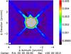
Fig. 8
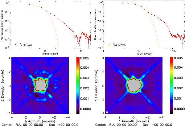
Top panel: radial profile of the NIKA beam pattern (red dots) including the secondary beam contribution for the 1.25 mm channel (left) and 2.14 mm channel (right) in the case of Uranus observations. We are able to measure the beam pattern profile up to scales of about 100 arcsec. At larger distances we do not have enough signal-to-noise. For illustration we also show the NIKA measured primary beam. Bottom panel: map of the far side lobes for 1.25 mm channel (left) and for 2.14 mm channel (right). The maps are derived using observation of Saturn. These maps are compatible with the 2D structure of the beam pattern of the IRAM 30 m telescope described in Greve et al. (1998); Kramer et al. (2013). The diffraction ring seen at 1.25 mm at about 2 arcmin radius, corresponds to the diffraction ring due to panel buckling. The spider supporting the secondary mirror of the telescope is visible to a level of about −30 dB.
Current usage metrics show cumulative count of Article Views (full-text article views including HTML views, PDF and ePub downloads, according to the available data) and Abstracts Views on Vision4Press platform.
Data correspond to usage on the plateform after 2015. The current usage metrics is available 48-96 hours after online publication and is updated daily on week days.
Initial download of the metrics may take a while.