Fig. 3
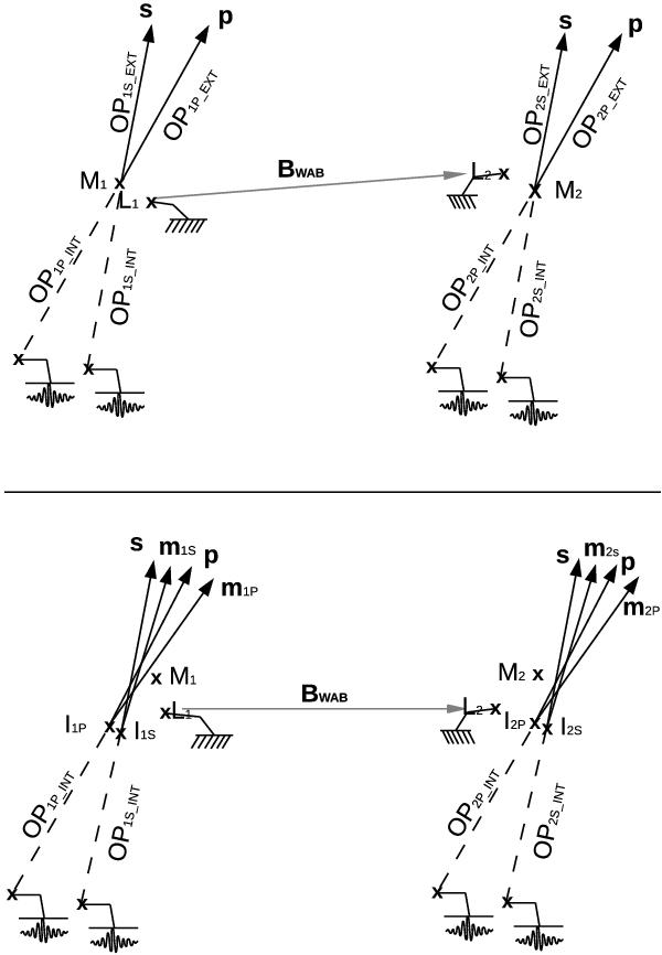
Schematic view of an astrometric interferometer. The light paths are virtual, as seen from the star, and all mirrors are removed, resulting in a straight line from the star to the beam combiner. Only the wide angle baseline (WAB) is represented, but all the baselines limit points are represented. L1 and L2 are the pivot points of the telescopes:  . The M1 and M2 points are the end points of the metrology:
  . Last, IP1, IP2, IS1 and IS2 are the barycenters of the effective pupils of each beam combiners:
  for the first combiner and
  for the second. Upper panel: the metrology measurement is made between the beam combiners and the metrology end point. The end points are different from the pivot points, which justify in Eq. (13) the use of the narrow angle baseline instead of the WAB. Lower panel: full schematic representation of the interferometer, including the presence of the imaging limit points. Imaging limit points are necessary to account for error terms due to difference in the propagation direction of the metrology (m1S, m2S, m1P and m2P) with respect to the stellar beams (s and p). It introduces additional error terms that are stated in Eq. (21).
Current usage metrics show cumulative count of Article Views (full-text article views including HTML views, PDF and ePub downloads, according to the available data) and Abstracts Views on Vision4Press platform.
Data correspond to usage on the plateform after 2015. The current usage metrics is available 48-96 hours after online publication and is updated daily on week days.
Initial download of the metrics may take a while.