Fig. 1
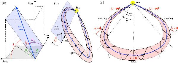
Definitions of the angles and flux-rope geometry. a) Schema defining the
angles of the local MC axis direction. It is a local view of panel b).
The unit vector  points toward the Sun and ẑGSE is orthogonal to the ecliptic
and northward. φ and θ are respectively the
longitude and the latitude of the MC axis (spherical coordinates with the polar axis
zGSE). The axis direction can also be defined by
i and λ angles, which are the inclination and the
position angle respectively (spherical coordinates with the polar axis
xGSE). βA is the cone angle
defined from
points toward the Sun and ẑGSE is orthogonal to the ecliptic
and northward. φ and θ are respectively the
longitude and the latitude of the MC axis (spherical coordinates with the polar axis
zGSE). The axis direction can also be defined by
i and λ angles, which are the inclination and the
position angle respectively (spherical coordinates with the polar axis
xGSE). βA is the cone angle
defined from  to the MC axis. All the angles φ,θ,λ and i are drawn
with positive values. b) Schema showing the large-scale meaning of
i when the flux rope axis is in a plane (light blue, drawn
northward of the radial Sun-spacecraft direction). c) Schema showing the
large-scale meaning of λ and drawn in the plane of the flux rope
axis. This plane in 3D is inclined by an angle i on the ecliptic
(left panels). Examples of spacecraft trajectories across the flux
rope are shown with radial dashed lines supposing that the flux rope is expanding
radially away from the Sun.
to the MC axis. All the angles φ,θ,λ and i are drawn
with positive values. b) Schema showing the large-scale meaning of
i when the flux rope axis is in a plane (light blue, drawn
northward of the radial Sun-spacecraft direction). c) Schema showing the
large-scale meaning of λ and drawn in the plane of the flux rope
axis. This plane in 3D is inclined by an angle i on the ecliptic
(left panels). Examples of spacecraft trajectories across the flux
rope are shown with radial dashed lines supposing that the flux rope is expanding
radially away from the Sun.
Current usage metrics show cumulative count of Article Views (full-text article views including HTML views, PDF and ePub downloads, according to the available data) and Abstracts Views on Vision4Press platform.
Data correspond to usage on the plateform after 2015. The current usage metrics is available 48-96 hours after online publication and is updated daily on week days.
Initial download of the metrics may take a while.