Fig. 5
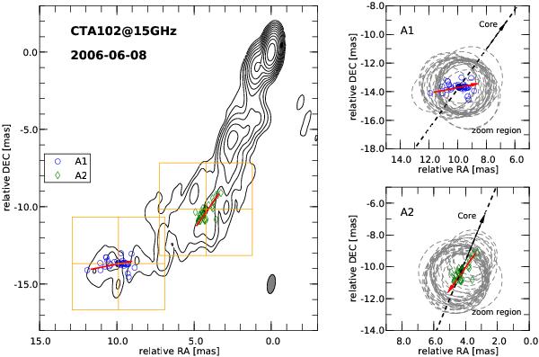
Vector motion fits and position of the fitted component in the sky. Left: 15 GHz CLEAN VLBI map of the 2006 June observations of CTA 102. The lowest contour level is drawn at 10 × the off-source rms, and the contours increase with steps of 2. The observational beam is plotted in the bottom right corner. The blue open symbols indicate the position of the components labeled as A1 and A2. The filled symbol corresponds to the component position at the middle time, t0, and the red solid line to the trajectory of the feature. The orange squares show the zoom region. Right: zoom region for the individual components. The dashed gray circle are the components size (FWHM) and the dashed black line and black arrow correspond the direction to the core drawn from the position of the component at t0. The red solid line illustrates the trajectory of the component, and the direction of the component is indicated by the arrow.
Current usage metrics show cumulative count of Article Views (full-text article views including HTML views, PDF and ePub downloads, according to the available data) and Abstracts Views on Vision4Press platform.
Data correspond to usage on the plateform after 2015. The current usage metrics is available 48-96 hours after online publication and is updated daily on week days.
Initial download of the metrics may take a while.