Fig. 5
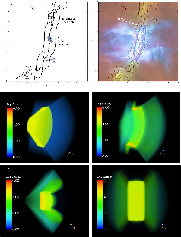
Illustration of the proposed scenario. Observations: a) Schematic view of the initial ridge as derived in Sect. 3.2. b) Modelled ring superimposed on the Herschel 3-colour image. Numerical simulations: c) Cut through the plane of the initial ridge. The radius of the yellow circular section is 1 pc. The density is given in H i cm-3. d) Cut through the plane of the ridge after ionisation reshaped it and formed a ring. e) Cut of d) from above. The bipolar shape clearly appears. f) Cut of d) from the backside. The ridge/filament projected shape clearly appears. The orientation of each cut is given by x, y, z axes on each image.
Current usage metrics show cumulative count of Article Views (full-text article views including HTML views, PDF and ePub downloads, according to the available data) and Abstracts Views on Vision4Press platform.
Data correspond to usage on the plateform after 2015. The current usage metrics is available 48-96 hours after online publication and is updated daily on week days.
Initial download of the metrics may take a while.