| Issue |
A&A
Volume 657, January 2022
|
|
|---|---|---|
| Article Number | A79 | |
| Number of page(s) | 12 | |
| Section | The Sun and the Heliosphere | |
| DOI | https://doi.org/10.1051/0004-6361/202141231 | |
| Published online | 14 January 2022 | |
Observational evidence for two-component distributions describing solar magnetic bright points
1
Universidad Nacional de Colombia, Bogotá, Colombia
e-mail: This email address is being protected from spambots. You need JavaScript enabled to view it.
2
Institute of Physics, Faculty of Science, University of South Bohemia, České Budějovice, Czech Republic
3
Computational Neurosciences, Neuromed Campus, Kepler University Hospital, Linz, Austria
e-mail: This email address is being protected from spambots. You need JavaScript enabled to view it.
4
Instituto de Astrofísica de Andalucía IAA-CSIC, Granada, Spain
5
Universidad Nacional de Colombia, Observatorio Astronómico Nacional, Bogotá, Colombia
e-mail: This email address is being protected from spambots. You need JavaScript enabled to view it.
6
University of Graz, Graz, Austria
7
Instituto de Astrofísica de Canarias, Tenerife, Spain
8
Departamento de Astrofísica, Universidad de La Laguna, La Laguna, Tenerife, Spain
9
Astronomical Institute, Slovak Academy of Sciences, Tatranská Lomnica, Slovakia
10
Leibniz – Institute for Astrophysics Potsdam, Potsdam, Germany
Received:
30
April
2021
Accepted:
30
September
2021
Abstract
Context. High-resolution observations of the solar photosphere reveal the presence of fine structures, in particular the so-called Magnetic Bright Points (MBPs), which are small-scale features associated with strong magnetic field regions of the order of kilogauss (kG). It is especially relevant to study these magnetic elements, which are extensively detected in all moments during the solar cycle, in order to establish their contribution to the behavior of the solar atmosphere, and ultimately a plausible role within the coronal heating problem.
Aims. Characterisation of size and velocity distributions of MBPs in the solar photosphere in two different datasets of quiet Sun images acquired with high-resolution solar instruments i.e. Solar Optical Telescope SOT/Hinode and the High-resolution Fast Imager HiFI/GREGOR, in the G-band (4308 Å).
Methods. In order to detect the MBPs, an automatic segmentation and identification algorithm is used. Next, the identified features were tracked to measure their proper motions. Finally, a statistical analysis of hundreds of MBPs is carried out, generating histograms for areas, diameters and horizontal velocities.
Results. This work establishes that areas and diameters of MBPs display log-normal distributions that are well-fitted by two different components, whereas the velocity vector components follow Gaussians and the vector magnitude a Rayleigh distribution revealing again for all vector elements a two component composition.
Conclusions. The results can be interpreted as due to the presence of two different populations of MBPs in the solar photosphere one likely related to stronger network magnetic flux elements and the other one to weaker intranetwork flux elemens. In particular this work concludes on the effect of the different spatial resolution of GREGOR and Hinode telescopes, affecting detections and average values.
Key words: Sun: photosphere / Sun: evolution / methods: observational
© ESO 2022
1. Introduction
High-resolution observations of the solar photosphere reveal a plethora of exceedingly fine structures, mainly corresponding to Magnetic Bright Points (MBPs), which are small-scale features associated with strong magnetic field regions of the order of up to kilogauss (1.5 kG; Nisenson et al. 2003; Beck et al. 2007; Ishikawa et al. 2007; Utz et al. 2013; Keys et al. 2019). MBPs are found all over the photosphere, in both quiet and active regions of the Sun, in particular located in the intergranular lanes in between granular convective cells (e.g., Muller et al. 1989). Several investigations have found the mean diameter of a MBP in a range of 100–300 km, its horizontal average velocity between 0.2 and 5 km s−1 and average lifetimes of 2.5–10 min, as shown by the results of Sánchez Almeida et al. (2004), Beck et al. (2007), Utz et al. (2010), Liu et al. (2018), among others.
According to Sánchez Almeida et al. (2004), the presence of MBPs in the solar photosphere was first reported by Dunn & Zirker (1973). Since then, MBPs have been extensively, but still not fully, investigated from the various viewpoints of theory (e.g., Spruit 1979; Parker 1978; Deinzer et al. 1984), observations (exemplarily: Berger et al. 2007; Viticchié et al. 2009), and simulations (Danilovic et al. 2010; Riethmüller et al. 2014). Among the better covered aspects of MBPs are their general characteristics as well as their formation which is believed to be due to the convective collapse theory introduced by Spruit (1979) as well as Parker (1978) and shown impressively in observations by Nagata et al. (2008) in a case study and on statistical grounds by Fischer et al. (2009). Other authors also tried to identify the formation of MBPs in numerical simulations and compared them with observations, e.g., Danilovic et al. (2010). Another hot topic is MBP and MHD waves as these waves can contribute to the solar atmospheric heating (see, e.g., Jess et al. 2009; Vigeesh et al. 2009; Fedun et al. 2011). Aspects similarly important but less extensively covered are the long-time evolution of MBP pattern with the solar cycle and their relationship to a possible surface dynamo and/or global dynamo (e.g., Utz et al. 2016, 2017), or the relationship of MBPs and the formation of solar spicules (e.g., Samanta et al. 2019) showed that magnetic flux cancellation between intranetwork fields and network fields represented by MBPs leads to the formation of spicules.
MBPs can exist as isolated features as well as form groups as reported by Nisenson et al. (2003) and Berger & Title (1996). Their dynamics can be seen as highly influenced by the surrounding granulation pattern and they themselves are being pushed by granules giving rise to a more or less chaotic movement pattern (e.g., Muller 1983; Stanislavsky & Weron 2009). Nisenson et al. (2003) and Berger & Title (1996) also found that two MBPs can come together and form only one (coalescence), or one can divide into two smaller MBPs (fragmentation). In particular Berger & Title (1996) analysed images in the G-band and in the continuum, acquired with the Swedish Vacuum Solar Telescope (SVTS; Scharmer et al. 1985) at the Observatorio Roque de los Muchachos in La Palma, Canary Islands, Spain, finding rapid fragmentation and coalescence in a sample of MBPs under analysis.
MBPs correspond to thin tubes of magnetic flux as explained by Steiner et al. (2001), which are widening in diameter going from the photosphere to upper heights. When these magnetic elements are observed in high-resolution filtergrams of the solar photosphere, they look brighter than their surroundings (Zakharov et al. 2005). This is due to the higher magnetic field concentration inside the flux tube generating a strong magnetic pressure and, in order to maintain the equilibrium, the gas pressure inside the tube needs to be reduced. This chain of causal effects leads ultimately to lower densities inside the flux tube (see Schüssler et al. 2003). The dynamic process to reach the equilibrium is called convective collapse and more details can be found in the works of Spruit (1979), Parker (1978). Due to the lower density, also the opacity decreases giving rise to a higher contribution of emission of radiation from deeper layers and thus increasing the overall brightness of the MBP structure. Added to this, the hot walls of the flux tube can also contribute with an excess of radiation, especially when viewed off the disk centre (for more details see Steiner et al. 2001).
The study of these magnetic elements is considered relevant to establish their plausible contribution to the behavior of the solar atmosphere, and ultimately to the well-known coronal heating problem (among many others, e.g., Klimchuk 2006; Erdélyi & Ballai 2007). As Choudhuri et al. (1993) explained, although being small, MBPs could significantly contribute to the energy budget in the corona as they harbour strong magnetic fields, and are spread over the entire surface of the Sun. Theoretically, the movement of the footpoint of a MBP could generate a flow of energy that ascends to the corona and can contribute to its heating (e.g., via the generation of Alfvén waves; Jess et al. 2009; Mathioudakis et al. 2013). Observations of MBPs can also be acquired in other wavelengths. According to Nisenson et al. (2003), MBPs and the filigree (chains of bright features located over the intergranular lanes) are observed in lines of the solar spectrum such as Hα, Ca II H and K; i.e. lines formed in the chromosphere. Furthermore, the Na I D1 and D2 lines can also be used to identify MBPs, as well as the photospheric Si I 10 827 Å and Ca I 10 839 Å lines (Jess et al. 2010; Kuckein 2019). Wiehr & Bovelet (2009) found a preferred location of these structures (that they called magnetic inter-granular structures) at the footpoints of dark Hα fibrils, which are known to delineate the network boundaries.
In this work, the analysis of MBPs is done by means of time series of images of the solar photosphere acquired with high-resolution ground-based and space-borne solar telescopes, i.e. with the Solar Optical Telescope instrument (SOT; Tsuneta et al. 2008) of the Hinode mission (see Kosugi et al. 2007) on the one hand and the High-resolution Fast Imager (HiFI; Kuckein et al. 2017) placed at GREGOR, instrument observing in the G-band (4308 Å) on the other hand.
We focus on the detection of MBPs by means of an automatic segmentation and identification algorithm described in Utz et al. (2014), to further track their evolution in order to characterise their dynamics and some of their physical parameters. Section 2 describes the data sets and the algorithm used. In Sect. 3 we give the results of the analysis, in Sect. 4 we discuss the influence of intensity cut-offs and spatial resolution and in Sect. 5 we refer to the principal discussion. Finally, the main conclusions are presented in Sect. 6.
2. Observational data and methodology
This study makes use of data sets taken on two different days with two different telescopes. The Hinode set (henceforth dataset-H) consists of 332 images acquired with the Hinode satellite, specifically with the Solar Optical Telescope (SOT; Tsuneta et al. 2008). These data correspond to solar observations acquired on March 10, 2007, spanning from 7:00 to 9:59 UT. The temporal resolution is 30 s with a spatial sampling resolution of 0 108 per pixel. The Field-of-View (FOV) is 55
 8 × 111
 6 (see bottom-left panel in Fig. 1). These observations are not affected by the adverse effects of the atmospheric seeing. On the other hand, the GREGOR telescope (Schmidt et al. 2012; Kleint et al. 2020) dataset (henceforth dataset-G) consists of 769 images acquired on July 13, 2019 with the HiFI instrument and spanning from 7:38 to 08:48 UT. These data are characterised by presenting a temporal resolution of 5 s, a pixel size of 0
 0286 per pixel and a FOV of 32
 4 × 26
 0 (see top-left panel in Fig. 1). Despite these observations being affected by atmospheric seeing, corrections made with the adaptive optics system (Berkefeld et al. 2012) considerably improved the image quality. Figure 1 (left panels) shows the corresponding FOV (in G-band images) for dataset-G and dataset-H, as labeled.
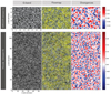 |
Fig. 1. G-band images, map of velocities, and map of divergences (from left to right) for dataset-G (top panels) and dataset-H (bottom panels). The red/black crosses mark the MBPs identified in the FOV. Note that the spatial scales are different for each data set. |
The first step, before applying the analysis algorithms, is to focus on the data reduction. Dataset-H is acquired in zero level of calibration from the freely accessible Hinode data base. The calibration is performed with the SolarSoft routine fg_prep implemented in the Interactive Data Language (IDL); the routine executes a general reduction of intrinsic errors including flat field, dark current and bad pixels. Dataset-G is calibrated using the data reduction pipeline sTools (Kuckein et al. 2017), which includes dark-current and flat-field corrections, as well as image selection. Then, speckle interferometry (Wöger & von der Lühe 2008) is used to produce level-2 data, which further corrects aberrations caused by the atmosphere as explained by Kuckein et al. (2017).
Finally, the two data sets are corrected from intensity disparities. When one evaluates the intensity level of the images organised in a data cube, it is found that each image can vary slightly in the dynamic range of intensities as well as its central intensity. Therefore, it is necessary to perform an intensity recalibration process that consists of modifying the dynamic range1 of the images in such a way that the range keeps the same for all images. In the same way, the average intensity of all the images should be put at the same value. In this way it is guaranteed that all the images have a constant intensity range. Figure 2 illustrates this process in more detail. The figure depicts two intensity histograms in continuous blue and red lines for image 1 and 2, respectively, before the process of intensity recalibration; it can be seen that both the dynamic range and the mean intensity are different. The intensity histograms in dashed-dotted style depict the recalculated histograms after the normalisation process was applied for each image, respectively. It can be evidenced that both, the dynamic range and mean intensity for the two images, are statistically similar now as expected for images of the quiet Sun.
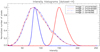 |
Fig. 2. Intensity histograms from two images, before (continuous lines) and after (dashed-dotted lines) the intensity recalibration process is applied. |
After the pre-processing is completed, the identification of MBPs is made with an automatic algorithm of detection based on the following steps: firstly, each image is segmented in the following way by multiple-thresholding. In a first step the brightest pixel of the image is detected and initializes the first segment. In the next step an intensity threshold slightly lower to the intensity level of the brightest pixel is applied and the newly found pixels which border the existing segment are added to the existing segment. Those pixels which are left (do not border the existing segment) initialize new segments. After that, the same process is repeated with the succeeding lower intensity threshold. Thus by going through the whole image intensity range from the brightest to the darkest pixel the image is broken up into image segments (practically local intensity maxima initialize segments which grow in size until they reach the boundary of other segments). Subsequently, MBPs in each created segment are detected based on the brightness gradient.
Once the MBPs have been identified (in the case of GREGOR about 110 MBPs per image and about 170 for Hinode; yielding a total number of detected MBP instances of 87 000 for GREGOR, and 56 000 for Hinode, respectively) their size in pixels is calculated; areas in km2 are determined and subsequently their diameters in km calculated, assuming that the MBP features have a circular shape, which is considered a good approximation for the purposes of this analysis comparing relative sizes of MBPs when detected by different instruments2. Histograms for area and diameter are presented and commented in detail in Sect. 3. Furthermore, the brightness barycenters of each MBP are calculated.
Finally, these tiny elements are tracked in a sequence of images with the purpose of determining their dynamic and evolutionary characteristics. This procedure consists in comparing the intensity barycentre position of one MBP in an image with all the found barycentre MBP positions in the next time instance. If the distance between two positions is less than or equal to one pre-established maximum distance, then the two individual detections of MBPs belong to the same MBP time sequence3 The maximum distance parameter can be found by the following two considerations: (i) the allowed distance must be high enough to allow for the highest possible velocities which can be estimated by, e.g., taking 3.5 times the previously established larger MBP velocities of about 4 km s−1 (e.g., in the work of Nisenson et al. 2003, one can see a velocity tail starting roughly with 4 km s−1 extending up to (6–8) km s−1); and ii) by being small enough so that one would not connect a non-involved MBP into the time series. This can be estimated by keeping the maximum distance smaller than an average MBP diameter (about 70 km). Both considerations together speak for a search distance of about 70 km or with a time cadence of 5 s, translating to the maximum detectable velocities of about 14 km s−1. By applying these processing steps to all the images and detected MBPs we obtain the time sequences and evolution of all the MBPs. In order to calculate MBP velocities, barycentre displacements between MBPs identified by the algorithm in subsequent frames are utilized. This leads finally to the estimation of their velocities and their statistical velocity distributions.
3. Distribution of sizes and velocities of MBPs
In order to characterise the dynamics of the MBPs in the photosphere in quiet Sun regions, this section deals with the analysis of areas, diameters and velocities, in particular for dataset-G as it represents the highest-resolution data used in this work. The actual sizes of the MBPs are calculated by applying either a 50% or 80% cut-off level on each of the segments identified to be a MBP (for more details refer to Sect. 5), the final histograms of the distribution of areas and diameters are illustrated in Fig. 3. Here we used a binning of the original size in pixels of 1 and then recalculated the corresponding size in km2, as well as the diameter in km. As this transformation is a non-linear process (via the square root function) the binning looks quenched to larger diameters in this representation. The red curves in the figure represent the log-normal fits for every distribution, and the curves in green correspond to two underlying different components that constitute the distributions in red and each of these is interpreted as a group of MBPs with well-defined characteristic. As evidenced in Fig. 4, the wing is not well represented by a one-component fit, and therefore the need arises for including a second component to better depict the histogram. Moreover, when computing the X2 test values to quantify the goodness of the fit by using the observed frequencies (i.e. values obtained in the data) and expected frequencies (i.e. theoretical values set by the fit), similar to Crockett et al. (2010), one finds a value of 1.3 for the one component fit model which yields a p-value of 0.5 meaning that there is only a 50–50 likelihood that the one component model is truly fitting the observed data. However, when computing the X2 value for the two-component model (2.6) the picture changes as the p-value now reaches 0.8 meaning that there is now a 80 percent likelihood that the model truly fits the measurement values. Practically a one component model is just not flexible enough to produce a fit well enough to clearly be able to reproduce the data. The vertical line in blue at 45 km in Fig. 4 represents the diffraction limited spatial resolution of the GREGOR telescope at the given wavelength.
 |
Fig. 3. Area distributions (panels a,c) and diameter distributions (panels b,d). Both cases are shown for the dataset-G with cut-off of 50% (panels a,b) and 80% (panels c,d). The plots depict a distribution with a log normal fit (red curves) and the two components (green curves). The blue vertical line around 2000 km2 (45 km) for area (diameter) indicates the spatial resolution by diffraction of GREGOR. |
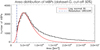 |
Fig. 4. Area distribution of MBPs for dataset-G (cut-off 50%) showing a one-component only fit (in red). Evidently, the tail of the histogram is not well-fitted, leading to the idea of two-component fit. |
The distribution of the areas for 50% (see panel a in Fig. 3) exhibits a mean value of μ = 5700 ⋅ ∣ ÷ 1.6 km24 for the first component (I), that corresponds to 73% of the total distribution, being a more numerous group. Due to their sizes, this component likely corresponds to newborn MBPs or MBPs in formation, with an area range of 2200–15 000 km2. As for the second component (II), the mean value is μ = 16 000 ⋅ ∣ ÷ 1.6 km2, that corresponds to 27% of the total; this component also represents a family of MBPs but mature ones, with bigger areas in the range 6300–40 000 km2 but decreased in quantity. Table 1 lists the mean values of the distributions together with the factor that multiplies and divides it. The factor (e.g., the value 1.6) is proper of this type of curves, representing the value that multiplies and divides the mean value and indicates the shape of the distribution (log-normal; for more details see Limpert et al. 2008). These results are in agreement with previous studies (e.g., Utz et al. 2009; Crockett et al. 2010), which established values between 7000 and 70 000 km2 for the area of MBPs. Although our obtained mean value of 5700 km2 is smaller than some of the previous calculations, it can be understood as evidence for the higher resolution of the GREGOR telescope affecting the detection procedure. For instance, Crockett et al. (2010) found a peak in the area distribution at 45 000 km2 using both, G-band observations from the 76 cm Dunn Solar Telescope (DST) with a diffraction limit at 10 000 km2 and numerical simulations using the MURaM code (Vögler et al. 2005).
Areas and mean diameters for the different datasets (G and H), cut-offs (50 and 80%) and components (I and II).
Similarly, the distribution of diameters (see panel b in Fig. 3) has a mean value of μ = 80 ⋅ ∣ ÷ 1.3 km for the 70% of the total distribution in the first component. Compared to that, the second component has a mean diameter of μ = 130 ⋅ ∣ ÷ 1.6 km for the 30% of the distribution (see Table 1). Once more, each component (dotted green lines in Fig. 3), of this distribution depicts a population of small MBPs or in process of formation/disintegration. The first of these populations, with greater number of cases, remains in a diameter range of 50–140 km. Moreover, the second population of MBPs, that is characterised by having less number of elements, exhibits diameters spanning in a range from 50 to 330 km.
Figure 5 shows the velocity distribution for the same data set in their velocity components vx and vy together with the surface and scatter plots. Here, and in the following, positive values for vx represent movement to the right, while a positive value for vy means a movement to the top of the image (images oriented with solar north to the top of the image). The analysed velocities were calculated in a frame by frame, or MBP instance by MBP instance, fashion without considering any temporal averaging (except of the unavoidable averaging by the given cadence of the data). The velocity histogram, shown in panel c in the figure, is fitted by a Rayleigh function (red) that can be split into two components (green). The mean value for the first component (I) of the velocity (see panel c in Fig. 5), that represents the 67% of the total distribution, is μ = 7.5 km s−1. For the second component (II), the mean value is μ = 1.9 km s−1 with 33% of the total. Each component plausibly indicates a different population of MBPs, as will be discussed in Sect. 4, the first of which exhibits a velocity in the range between 0 and 13 km s−1 and is more numerous. Accordingly, the second component depicts a population of MBPs with a velocity range from 0 to 5 km s−1 being less in number of elements. Unlike values for areas and diameters, velocity components vx and vy are well fitted by Gaussian distributions. Panels a and b in Fig. 5 show the frequency histograms of the velocity in x (vx) and in y (vx) with, again, evidence for a behaviour described by two components (component I and component II, as labeled for the green curves). A blue vertical line was located at the zero velocity value for clarity. In the case of the vx the mean value is found to be μ = 0.009 ± 4.8 km s−1 for component I with a 80% of the total distribution. This component represents a population of MBPs with a range from −14 to 14 km s−1 and is characterised by a higher number of elements. On the other hand, component II has a mean value of μ = −0.14 ± 1 km s−1 with 20% of the total (as listed in Table 2) and corresponds to a population of MBPs in a velocity range from −3 to 3 km s−1, besides it is characterised by a lower number of elements. Analogously, the distribution of vy has a mean value for the component I of μ = −0.08 ± 5.7 km s−1 with a total contribution of 63%, representing a population of MBPs featuring velocities within a range from −17 to 17 km s−1. This component features the higher number of elements, whereas component II has μ = −0.03 ± 1.4 km s−1 with a contribution of 37% to the total distribution, representing a population of MBPs, featuring velocities in the range from −4 and 4 km s−1. This second component is characterised by a lower number of elements. Both distributions, vx and vy, have similar behaviour, as can be evidenced in Fig. 5. In the same figure it can be noticed that the underlying population of MBPs for component II of velocity distributions corresponds to component I for area and diameter distributions. This behaviour can be interpreted as MBPs of smaller sizes belonging to a population that exhibits a more extended velocity distribution and thus larger velocities on average. Contrarily, larger MBPs are characterised by having lower velocities, i.e. component I velocity distributions correspond to component II distributions for area and diameter. Panel d in the figure aims at visualizing a 3D plot combining the information from vx and vy values, and a scatter plot that better evidences the central concentration of points.
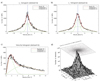 |
Fig. 5. Velocity histograms of MBPs for the GREGOR set. Top: vx and vy velocity components with the normal fit curve (red) and the two components of the distribution (green). Bottom left: velocity with the Rayleigh fit in red and the two components in green. Bottom right: surface and scatter plot of the vx and vy components. |
Mean velocity values (in km s−1) for the two datasets (G and H)and components (I and II).
4. Influence of intensity cut-off and spatial resolution: GREGOR versus Hinode
In the results described in Sect. 3 for dataset-G, a percentage of cut-off at 50% is used, that is to say, the commonly employed value by previous similar studies (see e.g., Berger et al. 1995). However, it is necessary to evaluate whether that definition, which is commonly used, yields the most accurate results. In order to do so, the definition that is established is based on finding the existing relationship between the size of MBPs and the percentage of intensity cut-off. Figure 6 represents the main scheme behind the characterisation of MBPs according to the intensity profile, displaying the enlargement in identified areas with the reduction of the intensity cut-off. The plot in panel b in Fig. 6 evidences that the more horizontal the curve is, the more independent the MBP size will be from the cut-off percentage parameter. Panel c shows the evolution of identified areas with the intensity thresholding in a sample image, for cut-off values of 0, 25, 50 and 80%, respectively. Black contours in the lower row highlight the corresponding areas, while red contours are overplotted to compare the area enlargement from one cut-off value to a lower one, and therefore affecting the recognized features, i.e. MBP core, MBP core and wall, the whole MBP and surroundings, and the MBP and some dark intergranular lanes. In panel b of the figure the stability zone is evidenced in the range from 60% to 100%. A median of 80% is the final representative value selected as the cut-off percentage (see also Bovelet & Wiehr 2001, who used a similar approach to ‘shrink’ detected granules to correct sizes). The description of the results using this new cut-off value is performed to compare both cut-off values at 50% and 80%. The examination of areas for this cut-off results in a two-component distribution with log-normal fits, as shown in panel c of Fig. 3, with the first component having a mean value of μ = 5700 ⋅ ∣ ÷ 1.6 km2 and representing 57% of the total distribution. Component I corresponds to a large family of newborn MBPs under formation, whose areas cover a range from 2200 to 15 000 km2. The other component is characterised by a mean value of μ = 20 000 ⋅ ∣÷ 1.6 km2 and depicts 43% of the total distribution; this second component corresponds to a family of mature MBPs with areas ranging from 7800 to 52 000 km2 but with a smaller number of elements. The previous results are within the range of other studies, like those described in Wiehr et al. (2004), Utz et al. (2009), Abramenko et al. (2010), Liu et al. (2018) to list a few, with established values between 7000 and 70 000 km2.
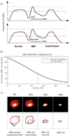 |
Fig. 6. Intensity characterisation of MBPs. Panel a: schematic side view cut of the solar surface in intensity with two granules and a MBP. The dashed horizontal line illustrates the cutting level and the following size of a segmented MBP. Panel b: criteria for setting the area of a MBP. The concept that underlies this criterion is based on finding a range of independence between the size of the MBP and the intensity cut-off percentage. Panel c: intensity thresholding (for values of 0, 25, 50 and 80%) applied over a segmented sample image and the effect on the identification of features, as labeled. The lower row represents contours in black for each frame in the upper row, and in red for every corresponding frame on the right, in order to compare the progressive area enlargement as the intensity threshold reduces from 80 to 0%. For exhaustive discussion refer to the main text. |
As for the distribution of diameters, shown in panel d in Fig. 3, the mean value corresponds to μ = 80 ⋅ ∣ ÷ 1.3 km, 70% of the total, for the first component; this corresponds to a group of MBPs with a range of diameters between 50 and 140 km and with a large number of elements. The second component has a mean value of μ = 150 ⋅ ∣ ÷ 1.5 km, 30% of the distribution; this corresponds to a group of MBPs with diameters from 70 to 340 km, with a lower number of elements. Table 1 summarizes the information for mean areas and diameters. In the panels c and d in Fig. 3, the blue vertical line around 2000 km2 (45 km) represents the spatial resolution limited by the diffraction of GREGOR for areas and diameters, respectively. The results for area and diameter for dataset-G do not change significantly when raising the cut-off value from 50% to 80%, as shown in panels a vs. c and b vs. d in Fig. 3. Indicating the superb quality of the GREGOR telescope and its HiFi instrument as well as the proper application of the identification and analysis algorithms as the results are practically independent of the chosen thresholding parameter.
Nevertheless, for the case of dataset-H, in which the spatial resolution is not as high, the results are strongly influenced by the thresholding as plotted in Fig. 7. Similarly as for dataset-G, these distributions also exhibit a bimodal contribution with two protruding peaks (components I and II). The fit parameters of the log normal fits are shown on Table 1. For the case of cut-off at 80%, shown in panel c in Fig. 7, the mean area of the first component is μ = 37 000 ⋅ ∣ ÷ 1.7 km2 and represents 71% of the total distribution. On the other hand, the mean value of the second component is μ = 115 000 ⋅ ∣ ÷ 1.2 km2 and corresponds to 29% of the total distribution. Values to the left from the blue vertical line are not reliable as they lie below the spatial resolution by diffraction for Hinode (i.e. 21 000 km2). Considering that the second component of the distribution surpasses the values reported in other studies, e.g., areas from 7000 to 70 000 km2 in Utz et al. (2009), Crockett et al. (2010), Abramenko et al. (2010), Yang et al. (2014), it is compelling to discuss the meaning of it. A plausible explanation relies on representing two different population of elements, one with areas in the range from 22 000 to 63 000 km2 that constitutes a family of MBPs (with greater number of elements), and the second with values from 96 000 to 138 000 km2 and likely to correspond to a family of small granules in process of formation or segments of granules, with a lower number of elements, considering the granules have values of area between the range of 105 000–2 600 000 km2 (Kawaguchi 1980).
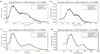 |
Fig. 7. Area distributions (panels a,c) and diameter distributions (panels b,d). Both cases are shown for the dataset-H with cut-off of 50% (panels a,b) and 80% (panels c,d). The plots depict a bimodal distribution with a log-normal fit (red curves) and the two components (green curves). The blue vertical line at 146 km (around 21 000 km2) indicates the spatial diffraction limit of Hinode. |
For the case of diameters computed with the same cut-off value (80%), the mean value of the first component of the bimodal distribution, plotted in panel d of Fig. 7, is μ = 260 ⋅ ∣ ÷ 1.5 km and corresponds to the 84% of the total, and with a greater of number elements. Diameters are in the range from 170 to 390 km, in agreement with the values reported by other studies (Utz et al. 2009), which are between 100 and 300 km. On the other hand, the mean value of component II is μ = 380 ⋅ ∣ ÷ 1.2 km, which corresponds to a population of forming granules (or fragments) with values from 310 to 450 km, and lower number of elements. This result is comparable to the range from 370 to 1800 km, found by Kawaguchi (1980).
To verify the precision in the definition of size described above, the distribution of the areas and diameters is calculated using the commonly definition (intensity cut-off at 50%). Panels a and b in Fig. 7 show the resulting two bimodal distributions that are fitted with log-normal curves (red), together with the two components that constitute it (green). Table 1 lists the fit parameters of such distributions. The mean value for the area of the first component is μ = 230 000 ⋅ ∣ ÷ 1.9 km2 and represents the 80% of the total distribution. For the second component, the value is μ = 490 000 ⋅ ∣ ÷ 1.2 km2, which corresponds to 20% of the total. Surprisingly, the component I of this distribution, with higher number of elements, shows now areas that are in the range between 120 000–400 000 km2. Thus changing the thresholding level in the case of Hinode changed quite dramatically the estimated size of the features. One has to keep in mind here that the same segments where identified in both cases and just the “estimation” of the true size changed by the parameter. A possible explanation for the effect of larger sizes is shown in Fig. 6. Panel a shows a schematic representation of the solar surface in a side-cut view. In between two granules we can find a MBP situated in the intergranular lane. The segmentation algorithm will grow all segments starting from the brightest pixel until the growing segments will stop their growth when encountering a neighbouring segment at the darkest intergranular pixels. Thus, a MBP segment can contain quite a large extent of the intergranular area and needs after segmentation to be cut down to the brightest part (corresponding to the true size of the MBP). If the cut-off, however, is chosen too low, the MBP size can be artificially extended by intergranular dark lane pixels. One can see that varying the cut-level by about 20% of the brightest intensity does not lead to a significant change of size, as shown in panel b in Fig. 6. This means that the brightest pixels of an MBP (the core structure) have homogenous brightness distribution, and thus they are under equivalent physical conditions. Taking the threshold to lower brightness levels, the structure increases in size as more pixels surrounding the brightest core of the structure are added. It is preferable to choose a threshold sufficiently high as well as in a part of the curve where it is nearly horizontal as this corresponds to a greater independence of the estimated size from the chosen threshold parameter. Thus the first component is also at the 50% cut-off level truly an MBP size distribution, however, sizes are estimated too large by a too deep cut level. The second component found in the Hinode data (Fig. 7) is interpreted as corresponding to a family of granules with area in the range of 400 000–600 000 km2, but with a lower number of elements. These results are in agreement with the range found by Kawaguchi (1980) of 105 000–2 600 000 km2. By visually inspecting some of the images we confirm the second distribution is in agreement with false detection of small granules misinterpreted as MBPs. The analysis evidences that the value for the cut-off at 80% manifests greater detection accuracy i.e. 22 000–62 000 km2, whereas results based on the commonly definition provide very large sizes for the MBPs of the order of 122 000–500 000 km2. Table 1 compiles the fitted values. Mean value of the first component of this bimodal distribution is μ = 510 ⋅ ∣ ÷ 1.7 km and represents the 81% of the totality of the same, and for the second distribution is μ = 780 ⋅ ∣ ÷ 1.3 km with a 19%.
Moreover we can conclude that the resolution of Hinode is not sufficient to detect the bi-component composition of the size distribution of MBPs. Besides, due to the lower resolution there is a certain level of misidentified forming granules detected in the Hinode data set constituting the second component in the case of MBP size distribution for dataset-H.
Figure 8 shows the results for the computed velocities. Panels a and b in the figure depict the frequency histograms for the components x and y of the velocity, i.e. Vx and Vy, respectively, with the fitted curves in red (normal distribution) and the two components in green dotted curves. The fit parameters μ and σ are summarized in Table 2. Panel c in the figure displays the effective velocity fitted by Rayleigh distribution (red) and the two components (green). The mean velocity value for component I, that represents the 49% of the total distribution, is μ = 2.3 km s−1 and is characterised by displaying a velocity range from 0 to 6 km s−1 and with a slightly smaller number of elements. Component II has a mean value μ = 1.1 km s−1 and represents 51% of the total distribution; indicating a population of MBPs with a velocity range from 0 to 3 km s−1 and with a slightly higher number number of elements.
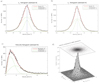 |
Fig. 8. Velocity histograms of MBPs for the Hinode set. Top: vx and vy velocity components with the normal fit curve (red) and the two components of the distribution (green). Bottom left: Velocity with Rayleigh fit in red and the two components in green. Bottom right: surface and scatter plot of the vx and vy components. |
We expressed the velocity components in 2 orthogonal directions (x, y; horizontal and vertical directions), which correspond to vx and vy, respectively, displaying Gaussian distributions as it is expected in the case of a non-preferential direction random walk process. A different outcome would only be expected if there were reasons for a large-scale flow-field with preferred directions like in the moat flows of sunspots. Panels a and b in Fig. 8 show the frequency histograms of vx and vy, respectively, fitted to normal curves (red) and the corresponding two components (green). A vertical line (blue) is located at the value of velocity equal to 0 km s−1 for clarity. The mean value for vx is μ = −0.063 ± 1.7 km s−1 for the component I (76% of the total) and represents a population of MBPs in a range from −5 to 5 km s−1 with greater number of elements. For component II, the mean value is μ = −0.00007 ± 0.7 km s−1, 24% of the total distribution, representing a population of MBPs in a range from −2.2 to 2.2 km s−1 but lower number of elements. For vy, the mean value is μ = 0.024 ± 1.5 km s−1 for component I (73% of the total) and μ = −0.024 ± 0.6 km s−1 for component II (27% of the total distribution). In panels a and b in Fig. 8 both, vx and vy, exhibit essentially the same distribution for the two components. Component I represents a population of MBPs with vy from −4.5 to 4.5 km s−1 with a slightly higher number of elements, whereas component II indicates a population of MBPs with vy from −1.9 to 1.9 km s−1 but with lower number of elements.
5. Discussion
It is well-known that the magnetic field inhibits convection and therefore plasma velocities are expected to reduce while the magnetic field intensifies. Thus, it is highly likely that this physical mechanism is underlying the two-component behaviour. Some previous investigations have dealt with velocity distributions of MBPs in different environments. Jafarzadeh et al. (2017) showed the variation in diffusion of MBPs across a network cell (with regions of flux emergence), whereas Keys et al. (2014) demonstrated the velocity distribution in three regions of varying background flux and show that MBPs in regions of higher flux have lower transverse velocities. The authors suggest that this is due to convection being disrupted in regions of higher flux, resulting in more regions of stagnation points for the MBPs reducing velocities. The regions of disrupted convection would relate to the small granules that are mentioned in this work. Convective cells are smaller in regions of higher flux, which, in turn, creates more regions where there are several intersecting intergranular lanes, forming the stagnation points where MBPs get trapped, thus resulting in a lower peaked velocity distribution (i.e. a peak at a lower velocity). We expect that the differences observed in our analysis are due to where the MBPs are found in the quiet-Sun regions (i.e. whether they can be classed as network or internetwork MBPs), but this requires further analysis of velocity flow maps, with the precise testing of parameters and comparison with magnetograms, for a definitive statement to be manifested. This will be the focus of a subsequent study.
The first group of MBPs, exhibiting lower velocities, are likely to harbour strong magnetic fields that impedes the rapid movement of this population. On the other hand, the second group, with greater velocities, would correspond to weaker magnetic fields letting them move faster while embedded in the photospheric plasma flow. And indeed there is a recent finding suggesting also, for the magnetic field strength distribution of MBPs, a bi-component composition as evidenced by Keys et al. (2019). Figure 1 shows (from left to right) G-band images of the FOV, map of velocities computed from local correlation tracking (LCT) techniques, and map of divergences for dataset-G (top row) and dataset-H (bottom row). This figure shows a spatial correspondence between the location of MBPs and lower velocities (red crosses in middle panels) and, in turn, with negative divergences (black crosses in right-most panels). Blue regions in the divergence maps are tracing intergranular lanes. This is in concordance with the presence of two populations of MBPs, one group located in the network (with stronger magnetic fields and thus likely the larger MBPs showing lower velocities) and the other population of MBPs located in the internetwork (with weaker magnetic fields, harboring smaller MBPs which can move faster), though a detailed analysis including magnetic field information is out of the scope of this analysis and will be covered in a future work.
Moreover the inspection of the results obtained by GREGOR and Hinode highlight the necessity for high spatial as well as temporal resolution as it is not possible to differentiate the two populations of MBPs in size with the Hinode instrument while it became apparent with the GREGOR data set. Besides, at the same time the higher resolution of GREGOR helps to eliminate the misidentified population of small granules. Moreover, we can find higher velocities by the GREGOR telescope which are related to the better temporal and spatial resolution as discussed in Utz et al. (2010). The authors claim and verify in Utz et al. (2012) that a random walk motion observed under higher temporal cadence conditions would yield higher velocities as the length of the travelled path between two fixed time instances of the MBP increases. Such results are of particular value for MHD wave simulations as more rapid footpoint motions of the flux-tube, i.e. MBP will yield MHD waves carrying more energy into the higher atmosphere or possibly creating the recently observed magnetic field line switchbacks (e.g., Choudhuri et al. 1993; Vigeesh et al. 2009; Magyar et al. 2021). Finally, with the hindsight of this work, it is even possible to find evidence for the two-component velocity distributions in earlier works such as Bodnárová et al. (2014) in which the authors used DOT (Dutch Open Telescope; Rutten et al. 2004) data. Evidently in their Fig. 2, depicting the magnitude of the MBP velocity, the second Rayleigh component has been left unnoticed by the authors, who, however, state that there is widening discrepancy for the high velocity tail compared to their one component Rayleigh fit.
6. Conclusions
In the present investigation, the study of the dynamics of MBPs on the solar photosphere for two quiet Sun regions, close to the central meridian of the solar disk, was carried out. Observations from ground-based and space-borne solar telescopes were employed, specifically using the HiFI/GREGOR and the SOT/Hinode instruments. Unprecedented results for the size, diameter, and velocity of MBPs were found as a direct consequence of the excellent spatial resolution of the observations with the GREGOR telescope. The results of the characterisation of physical parameters of MBPs are in correspondence with others found in previous investigations (see Muller et al. 1994; Utz et al. 2009; Crockett et al. 2010; Liu et al. 2018). The most important findings of the present investigation are related to the distribution of sizes, diameters, and velocities of MBPs. The results obtained with the two sets of observational data exhibit, for both area and diameter, a log-normal distribution, in agreement with previous observational and numerical studies (e.g., Crockett et al. 2010). As suggested by Bogdan et al. (1988), the underlying fragmentation process might be responsible for log-normal distributions. In this work, the log-normal distributions of areas and diameters are found to be well described by two different components, each of which is proposed to correspond to a different population of solar features. As for velocities of MBPs, results show a Rayleigh distribution with the presence of two clear components, representing different groups of MBPs. For dataset-H (Hinode), a population of MBPs in addition to small granules were found, in the area and diameter results. This is due to difficulties arising by the lower spatial resolution of the telescope. On the other hand, in the velocity results two populations of MBPs were found. Similarly, for dataset-G (GREGOR), two populations of MBPs were found for areas, diameters and velocities, and no misidentifications (small granules) were found. This is by virtue of the prominent resolution of the telescope. Finally, another finding related to the effect of the intensity cut-off is that the cut-off percentage value of 80% better describes the area and diameter of the MBPs under study, which were not so large but consistent with those found in Utz et al. (2009), Kawaguchi (1980). In our case, using the commonly used definition cut-off at 50%) resulted in misidentification of granules and excessively large values of MBPs for the results of area and diameter.
With this study at hand, and the previous study of Keys et al. (2019) describing two-component magnetic field strength distributions for MBPs, evidence is growing for a paradigm shift from a single population of MBPs to a more complex model, where we will have to deal in the future with two distinct types of MBPs, likely related to network and intranetwork magnetic fields and thus maybe even to the global magnetic field dynamo versus a shallow surface magnetic field dynamo. The new generation of solar telescopes, e.g., Daniel K. Inouye Solar Telescope (DKIST; Rast et al. 2021) and European Solar Telescope (EST; Jurčák et al. 2019) with larger apertures and, in turn, better spatial resolution, will shed more light to the two-component groups enabling further confirmation of the characterisation of MBPs presented in this study.
Defined here as the difference between the highest percentile of intensity values compared to the lowest percentile.
As Feng et al. (2013) showed, assuming an elliptical shape would be more precise as the modal value of the ratio between the major and minor axis of an equisized ellipse would be around 1.5. However, for comparison purposes we follow the tradition of assuming a round or circular shape and stating diameters for equisized circles as well as the raw results in the form of a size distribution.
Due to this definition it is explicitly allowed for MBPs that one temporal realization of an MBP can have several follow-up MBP realizations, i.e. splitting is allowed and can be detected. The estimation of such splitting and merging events as well as the rates of occurrence of such events will be an interesting topic of a future work.
Growth/fragmentation processes which follow multiplicative rules instead of additive rules follow log-normal distributions instead of normal distributions. This means that the additive standard deviation becomes a multiplicative standard deviation. For all the details see Limpert et al. (2008).
Acknowledgments
Part of this work was supported by Austrian FWF – Der Wissenschaftsfonds project number P27800 as well as the German Deutsche Forschungsgemeinschaft, DFG project number Ts 17/2–1. SVD acknowledges support by the Beyond Research Program between University of Graz and Universidad Nacional de Colombia. SJGM acknowledges the support of grants PGC2018-095832-B-I00 (MCIU) and ERC-2017-CoG771310-PI2FA (European Research Council). PG acknowledges the support of the project VEGA 2/0048/20. P.Z. acknowledges support from the Stefan Schwarz fund for postdoctoral researchers awarded by the Slovak Academy of Sciences. This research data leading to the results obtained has been supported by SOLARNET project that has received funding from the European Union’s Horizon 2020 research and innovation programme under grant agreement no 824135. The 1.5-meter GREGOR solar telescope was built by a German consortium under the leadership of the Kiepenheuer Institute for Solar Physics in Freiburg with the Leibniz Institute for Astrophysics Potsdam, the Institute for Astrophysics Göttingen, and the Max Planck Institute for Solar System Research in Göttingen as partners, and with contributions by the Instituto de Astrofísica de Canarias and the Astronomical Institute of the Academy of Sciences of the Czech Republic. The authors are grateful for the possibility to use Hinode data. Hinode is a Japanese mission developed and launched by ISAS/JAXA, collaborating with NAOJ as a domestic partner, NASA and UKSA as international partners. Scientific operation of the Hinode mission is conducted by the Hinode science team organized at ISAS/JAXA. This team mainly consists of scientists from institutes in the partner countries. Support for the post-launch operation is provided by JAXA and NAOJ (Japan), UKSA (UK), NASA, ESA, and NSC (Norway). We would like to express our gratitude to the anonymous referee for all the valuable comments that helped us you improve the presentation of the results and ideas highlighted in this work.
References
- Abramenko, V., Yurchyshyn, V., Goode, P., & Kilcik, A. 2010, ApJ, 725, L101 [NASA ADS] [CrossRef] [Google Scholar]
- Beck, C., Bellot Rubio, L. R., Schlichenmaier, R., & Sütterlin, P. 2007, A&A, 472, 607 [NASA ADS] [CrossRef] [EDP Sciences] [Google Scholar]
- Berger, T. E., & Title, A. M. 1996, ApJ, 463, 365 [NASA ADS] [CrossRef] [Google Scholar]
- Berger, T. E., Schrijver, C. J., Shine, R. A., et al. 1995, ApJ, 454, 531 [NASA ADS] [CrossRef] [Google Scholar]
- Berger, T. E., Rouppe van der Voort, L., & Löfdahl, M. 2007, ApJ, 661, 1272 [NASA ADS] [CrossRef] [Google Scholar]
- Berkefeld, T., Schmidt, D., Soltau, D., von der Lühe, O., & Heidecke, F. 2012, Astron. Nachr., 333, 863 [NASA ADS] [CrossRef] [Google Scholar]
- Bodnárová, M., Utz, D., & Rybák, J. 2014, Sol. Phys., 289, 1543 [CrossRef] [Google Scholar]
- Bogdan, T. J., Gilman, P. A., Lerche, I., & Howard, R. 1988, ApJ, 327, 451 [Google Scholar]
- Bovelet, B., & Wiehr, E. 2001, Sol. Phys., 201, 13 [NASA ADS] [CrossRef] [Google Scholar]
- Choudhuri, A. R., Auffret, H., & Priest, E. R. 1993, Sol. Phys., 143, 49 [NASA ADS] [CrossRef] [Google Scholar]
- Crockett, P. J., Mathioudakis, M., Jess, D. B., et al. 2010, ApJ, 722, L188 [NASA ADS] [CrossRef] [Google Scholar]
- Danilovic, S., Schüssler, M., & Solanki, S. K. 2010, A&A, 509, A76 [NASA ADS] [CrossRef] [EDP Sciences] [Google Scholar]
- Deinzer, W., Hensler, G., Schussler, M., & Weisshaar, E. 1984, A&A, 139, 435 [NASA ADS] [Google Scholar]
- Dunn, R. B., & Zirker, J. B. 1973, Sol. Phys., 33, 281 [NASA ADS] [Google Scholar]
- Erdélyi, R., & Ballai, I. 2007, Astron. Nachr., 328, 726 [CrossRef] [Google Scholar]
- Fedun, V., Shelyag, S., & Erdélyi, R. 2011, ApJ, 727, 17 [NASA ADS] [CrossRef] [Google Scholar]
- Feng, S., Deng, L., Yang, Y., & Ji, K. 2013, Ap&SS, 348, 17 [CrossRef] [Google Scholar]
- Fischer, C. E., de Wijn, A. G., Centeno, R., Lites, B. W., & Keller, C. U. 2009, A&A, 504, 583 [NASA ADS] [CrossRef] [EDP Sciences] [Google Scholar]
- Ishikawa, R., Tsuneta, S., Kitakoshi, Y., et al. 2007, A&A, 472, 911 [NASA ADS] [CrossRef] [EDP Sciences] [Google Scholar]
- Jafarzadeh, S., Solanki, S. K., Stangalini, M., et al. 2017, ApJS, 229, 10 [Google Scholar]
- Jess, D. B., Mathioudakis, M., Erdélyi, R., et al. 2009, Science, 323, 1582 [Google Scholar]
- Jess, D. B., Mathioudakis, M., Christian, D. J., Crockett, P. J., & Keenan, F. P. 2010, ApJ, 719, L134 [NASA ADS] [CrossRef] [Google Scholar]
- Jurčák, J., Collados, M., Leenaarts, J., van Noort, M., & Schlichenmaier, R. 2019, Adv. Space Res., 63, 1389 [Google Scholar]
- Kawaguchi, I. 1980, Sol. Phys., 65, 207 [CrossRef] [Google Scholar]
- Keys, P. H., Mathioudakis, M., Jess, D. B., Mackay, D. H., & Keenan, F. P. 2014, A&A, 566, A99 [NASA ADS] [CrossRef] [EDP Sciences] [Google Scholar]
- Keys, P. H., Reid, A., Mathioudakis, M., et al. 2019, MNRAS, 488, L53 [NASA ADS] [Google Scholar]
- Kleint, L., Berkefeld, T., Esteves, M., et al. 2020, A&A, 641, A27 [EDP Sciences] [Google Scholar]
- Klimchuk, J. A. 2006, Sol. Phys., 234, 41 [Google Scholar]
- Kosugi, T., Matsuzaki, K., Sakao, T., et al. 2007, Sol. Phys., 243, 3 [Google Scholar]
- Kuckein, C. 2019, A&A, 630, A139 [NASA ADS] [CrossRef] [EDP Sciences] [Google Scholar]
- Kuckein, C., Denker, C., Verma, M., et al. 2017, in Fine Structure and Dynamics of the Solar Atmosphere, eds. S. Vargas Domínguez, A. G. Kosovichev, P. Antolin, & L. Harra, 327, 20 [Google Scholar]
- Limpert, E., Stahel, W. A., & Abbt, M. 2008, BioScience, 51, 341 [Google Scholar]
- Liu, Y., Xiang, Y., Erdélyi, R., et al. 2018, ApJ, 856, 17 [NASA ADS] [CrossRef] [Google Scholar]
- Magyar, N., Utz, D., Erdélyi, R., & Nakariakov, V. M. 2021, ApJ, 911, 75 [NASA ADS] [CrossRef] [Google Scholar]
- Mathioudakis, M., Jess, D. B., & Erdélyi, R. 2013, Space Sci. Rev., 175, 1 [Google Scholar]
- Muller, R. 1983, Sol. Phys., 85, 113 [NASA ADS] [CrossRef] [Google Scholar]
- Muller, R., Hulot, J. C., & Roudier, T. 1989, Sol. Phys., 119, 229 [CrossRef] [Google Scholar]
- Muller, R., Roudier, T., Vigneau, J., & Auffret, H. 1994, A&A, 283, 232 [NASA ADS] [Google Scholar]
- Nagata, S., Tsuneta, S., Suematsu, Y., et al. 2008, ApJ, 677, L145 [NASA ADS] [CrossRef] [Google Scholar]
- Nisenson, P., van Ballegooijen, A. A., de Wijn, A. G., & Sütterlin, P. 2003, ApJ, 587, 458 [NASA ADS] [CrossRef] [Google Scholar]
- Parker, E. N. 1978, ApJ, 221, 368 [NASA ADS] [CrossRef] [Google Scholar]
- Rast, M. P., Bello González, N., Bellot Rubio, L., et al. 2021, Sol. Phys., 296, 70 [NASA ADS] [CrossRef] [Google Scholar]
- Riethmüller, T. L., Solanki, S. K., Berdyugina, S. V., et al. 2014, A&A, 568, A13 [Google Scholar]
- Rutten, R. J., Hammerschlag, R. H., Bettonvil, F. C. M., Sütterlin, P., & de Wijn, A. G. 2004, A&A, 413, 1183 [NASA ADS] [CrossRef] [EDP Sciences] [Google Scholar]
- Samanta, T., Tian, H., Yurchyshyn, V., et al. 2019, Science, 366, 890 [NASA ADS] [CrossRef] [Google Scholar]
- Sánchez Almeida, J., Márquez, I., Bonet, J. A., Domínguez Cerdeña, I., & Muller, R. 2004, ApJ, 609, L91 [CrossRef] [Google Scholar]
- Scharmer, G. B., Brown, D. S., Pettersson, L., & Rehn, J. 1985, Appl. Opt., 24, 2558 [NASA ADS] [CrossRef] [Google Scholar]
- Schmidt, W., von der Lühe, O., Volkmer, R., et al. 2012, Astron. Nachr., 333, 796 [Google Scholar]
- Schüssler, M., Shelyag, S., Berdyugina, S., Vögler, A., & Solanki, S. K. 2003, ApJ, 597, L173 [CrossRef] [Google Scholar]
- Spruit, H. C. 1979, Sol. Phys., 61, 363 [CrossRef] [Google Scholar]
- Stanislavsky, A., & Weron, K. 2009, Ap&SS, 104 [Google Scholar]
- Steiner, O., Hauschildt, P. H., & Bruls, J. 2001, A&A, 372, L13 [NASA ADS] [CrossRef] [EDP Sciences] [Google Scholar]
- Tsuneta, S., Ichimoto, K., Katsukawa, Y., et al. 2008, Sol. Phys., 249, 167 [Google Scholar]
- Utz, D., Hanslmeier, A., Möstl, C., et al. 2009, A&A, 498, 289 [NASA ADS] [CrossRef] [EDP Sciences] [Google Scholar]
- Utz, D., Hanslmeier, A., Muller, R., et al. 2010, A&A, 511, A39 [NASA ADS] [CrossRef] [EDP Sciences] [Google Scholar]
- Utz, D., Hanslmeier, A., Muller, R., et al. 2012, in Hinode-3: The 3rd Hinode Science Meeting, eds. T. Sekii, T. Watanabe, & T. Sakurai, ASP Conf. Ser., 454, 55 [NASA ADS] [Google Scholar]
- Utz, D., Jurčák, J., Hanslmeier, A., et al. 2013, A&A, 554, A65 [NASA ADS] [CrossRef] [EDP Sciences] [Google Scholar]
- Utz, D., del Toro Iniesta, J. C., Bellot Rubio, L. R., et al. 2014, ApJ, 796, 79 [NASA ADS] [CrossRef] [Google Scholar]
- Utz, D., Muller, R., Thonhofer, S., et al. 2016, A&A, 585, A39 [NASA ADS] [CrossRef] [EDP Sciences] [Google Scholar]
- Utz, D., Muller, R., & Van Doorsselaere, T. 2017, PASJ, 69, 98 [CrossRef] [Google Scholar]
- Vigeesh, G., Hasan, S. S., & Steiner, O. 2009, A&A, 508, 951 [NASA ADS] [CrossRef] [EDP Sciences] [Google Scholar]
- Viticchié, B., Del Moro, D., Berrilli, F., Bellot Rubio, L., & Tritschler, A. 2009, ApJ, 700, L145 [CrossRef] [Google Scholar]
- Vögler, A., Shelyag, S., Schüssler, M., et al. 2005, A&A, 429, 335 [Google Scholar]
- Wiehr, E., & Bovelet, B. 2009, Cent. Eur. Astrophys. Bull., 33, 19 [Google Scholar]
- Wiehr, E., Bovelet, B., & Hirzberger, J. 2004, A&A, 422, L63 [NASA ADS] [CrossRef] [EDP Sciences] [Google Scholar]
- Wöger, F., & von der Lühe, O. I. 2008, in Advanced Software and Control for Astronomy II, eds. A. Bridger, & N. M. Radziwill, SPIE Conf. Ser., 7019, 70191E [CrossRef] [Google Scholar]
- Yang, Y.-F., Lin, J.-B., Feng, S., et al. 2014, Res. Astron. Astrophys., 14, 741 [CrossRef] [Google Scholar]
- Zakharov, V., Gandorfer, A., Solanki, S. K., & Löfdahl, M. 2005, A&A, 437, L43 [NASA ADS] [CrossRef] [EDP Sciences] [Google Scholar]
All Tables
Areas and mean diameters for the different datasets (G and H), cut-offs (50 and 80%) and components (I and II).
Mean velocity values (in km s−1) for the two datasets (G and H)and components (I and II).
All Figures
|
Fig. 1. G-band images, map of velocities, and map of divergences (from left to right) for dataset-G (top panels) and dataset-H (bottom panels). The red/black crosses mark the MBPs identified in the FOV. Note that the spatial scales are different for each data set. |
| In the text | |
|
Fig. 2. Intensity histograms from two images, before (continuous lines) and after (dashed-dotted lines) the intensity recalibration process is applied. |
| In the text | |
|
Fig. 3. Area distributions (panels a,c) and diameter distributions (panels b,d). Both cases are shown for the dataset-G with cut-off of 50% (panels a,b) and 80% (panels c,d). The plots depict a distribution with a log normal fit (red curves) and the two components (green curves). The blue vertical line around 2000 km2 (45 km) for area (diameter) indicates the spatial resolution by diffraction of GREGOR. |
| In the text | |
|
Fig. 4. Area distribution of MBPs for dataset-G (cut-off 50%) showing a one-component only fit (in red). Evidently, the tail of the histogram is not well-fitted, leading to the idea of two-component fit. |
| In the text | |
|
Fig. 5. Velocity histograms of MBPs for the GREGOR set. Top: vx and vy velocity components with the normal fit curve (red) and the two components of the distribution (green). Bottom left: velocity with the Rayleigh fit in red and the two components in green. Bottom right: surface and scatter plot of the vx and vy components. |
| In the text | |
|
Fig. 6. Intensity characterisation of MBPs. Panel a: schematic side view cut of the solar surface in intensity with two granules and a MBP. The dashed horizontal line illustrates the cutting level and the following size of a segmented MBP. Panel b: criteria for setting the area of a MBP. The concept that underlies this criterion is based on finding a range of independence between the size of the MBP and the intensity cut-off percentage. Panel c: intensity thresholding (for values of 0, 25, 50 and 80%) applied over a segmented sample image and the effect on the identification of features, as labeled. The lower row represents contours in black for each frame in the upper row, and in red for every corresponding frame on the right, in order to compare the progressive area enlargement as the intensity threshold reduces from 80 to 0%. For exhaustive discussion refer to the main text. |
| In the text | |
|
Fig. 7. Area distributions (panels a,c) and diameter distributions (panels b,d). Both cases are shown for the dataset-H with cut-off of 50% (panels a,b) and 80% (panels c,d). The plots depict a bimodal distribution with a log-normal fit (red curves) and the two components (green curves). The blue vertical line at 146 km (around 21 000 km2) indicates the spatial diffraction limit of Hinode. |
| In the text | |
|
Fig. 8. Velocity histograms of MBPs for the Hinode set. Top: vx and vy velocity components with the normal fit curve (red) and the two components of the distribution (green). Bottom left: Velocity with Rayleigh fit in red and the two components in green. Bottom right: surface and scatter plot of the vx and vy components. |
| In the text | |
Current usage metrics show cumulative count of Article Views (full-text article views including HTML views, PDF and ePub downloads, according to the available data) and Abstracts Views on Vision4Press platform.
Data correspond to usage on the plateform after 2015. The current usage metrics is available 48-96 hours after online publication and is updated daily on week days.
Initial download of the metrics may take a while.