Fig. 18.
Download original image
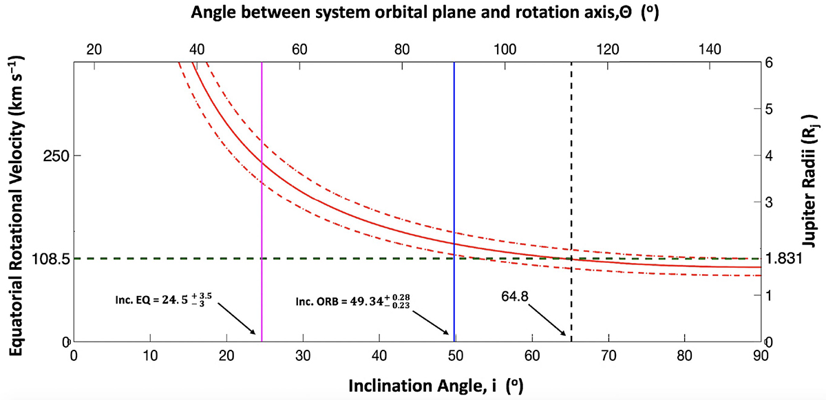
Same axis layout and illustration as Figure 17, but here we plot the results obtained from the scenario that the v sin i of 45 ± 5 km s−1 (red solid curve) is a combination from both components. The dashed red line corresponds to the measured error in the v sin i. The horizontal green dashed line in the plot represents the 1.831 ± 0.018 RJ radius estimate for the secondary component (Dupuy et al. 2016). The magenta vertical solid line shows the corresponding tentative equatorial inclination angle of 24.5![]() degrees for 2M J1314+13B. The orbital inclination angle of this system of 49.34
degrees for 2M J1314+13B. The orbital inclination angle of this system of 49.34![]() degrees (Dupuy et al. 2016) is highlighted by the blue vertical solid line. If the assumed scenario is true, we found that the equatorial inclination angle for the companion is not aligned with orbital plane system.
degrees (Dupuy et al. 2016) is highlighted by the blue vertical solid line. If the assumed scenario is true, we found that the equatorial inclination angle for the companion is not aligned with orbital plane system.
Current usage metrics show cumulative count of Article Views (full-text article views including HTML views, PDF and ePub downloads, according to the available data) and Abstracts Views on Vision4Press platform.
Data correspond to usage on the plateform after 2015. The current usage metrics is available 48-96 hours after online publication and is updated daily on week days.
Initial download of the metrics may take a while.