Fig. 4.
Download original image
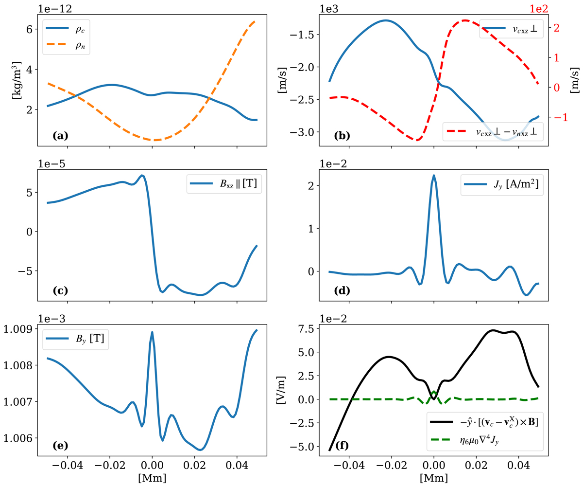
Profiles across a reconnecting current sheet at t = 534.5 s along the cut marked with the dashed blue line, labeled “⊥” in left panel of Fig. B.1 and centered with the 0 location along the cut to correspond to the X-point location in Fig. B.1. The panels show (a) mass density of neutrals (dashed orange line) and charges (solid blue line); (b) the flow velocity along the direction of the cut for the charges (solid blue line, left axis) as well as the relative drift between charges and neutrals (dashed red line, right axis); (c) the in-plane magnetic field component normal to the cut and along the current sheet; (d) the out-of-plane current density Jy; and (e) the out-of-plane magnetic field By. Panel f shows the calculated ideal electric field ![]() in the frame of reference of the charged fluid at the X-point (solid black line), and the ŷ-component of the effective dissipative electric field, η6μ0∇4Jy, present due to numerical dissipation (dashed green line). The width of the reconnection current sheet is measured to be λJ = 5.323 km as the full width at half max of the Jy profile in panel d.
in the frame of reference of the charged fluid at the X-point (solid black line), and the ŷ-component of the effective dissipative electric field, η6μ0∇4Jy, present due to numerical dissipation (dashed green line). The width of the reconnection current sheet is measured to be λJ = 5.323 km as the full width at half max of the Jy profile in panel d.
Current usage metrics show cumulative count of Article Views (full-text article views including HTML views, PDF and ePub downloads, according to the available data) and Abstracts Views on Vision4Press platform.
Data correspond to usage on the plateform after 2015. The current usage metrics is available 48-96 hours after online publication and is updated daily on week days.
Initial download of the metrics may take a while.