| Issue |
A&A
Volume 668, December 2022
|
|
|---|---|---|
| Article Number | A70 | |
| Number of page(s) | 13 | |
| Section | Planets and planetary systems | |
| DOI | https://doi.org/10.1051/0004-6361/202244386 | |
| Published online | 07 December 2022 | |
The crater-induced YORP effect
1
Université Côte d’Azur, Observatoire de la Côte d’Azur, CNRS,
Laboratoire Lagrange, 96 Bd de l’Observatoire,
06300
Nice, France
e-mail: This email address is being protected from spambots. You need JavaScript enabled to view it.
2
Origin Space Co. Ltd.,
Kechuang Road, Nanjing,
212415
Jiangsu, PR China
3
Department of Aerospace Engineering, University of Maryland,
College Park, MD,
20742, USA
4
Department of Aerospace Engineering, Tsinghua University,
30 Shuangqing Road,
100190
Beijing, PR China
Received:
30
June
2022
Accepted:
13
October
2022
Abstract
Context. The Yarkovsky–O’Keefe–Radzievskii–Paddack (YORP) effect plays an important role in the rotational properties and evolution of asteroids. While the YORP effect induced by the macroscopic shape of the asteroid and by the presence of surface boulders has been well studied, no investigation has been performed yet regarding how craters with given properties influence this effect.
Aims. We introduce and estimate the crater-induced YORP effect (CYORP), which arises from the concave structure of the crater, to investigate the magnitude of the resulting torques as a function of varying properties of the crater and the asteroid by a semi-analytical method.
Methods. By using a simple spherical shape model of the crater and assuming zero thermal inertia, we calculated the total YORP torque due to the crater, which was averaged over the spin and orbital motions of the asteroid, accounting for self-sheltering and self-sheltering effects.
Results. The general form of the CYORP torque can be expressed in terms of the crater radius R0 and the asteroid radius Rast: 〈TCYORP〉 ~ WR02RastΦ/c, where W is an efficiency factor. We find that the typical values of W are about 0.04 and 0.025 for the spin and obliquity component, respectively, which indicates that the CYORP can be comparable to the normal YORP torque when the size of the crater is about one-tenth of the size of the asteroid, or equivalently when the crater/roughness covers one-tenth of the asteroid surface. Although the torque decreases with the crater size R0 as ~R02, the combined contribution of all small craters can become non-negligible due to their large number when the commonly used power-law crater size distribution is considered. The CYORP torque of small concave structures, usually considered as surface roughness, is essential to the accurate calculation of the complete YORP torque. Under the CYORP effect that is produced by collisions, asteroids go through a random walk in spin rate and obliquity, with a YORP reset timescale typically of 0.4 Myr. This has strong implications for the rotational evolution and orbital evolution of asteroids.
Conclusions. Craters and roughness on asteroid surfaces, which correspond to concave structures, can influence the YORP torques and therefore the rotational properties and evolution of asteroids. We suggest that the CYORP effect should be considered in the future investigation of the YORP effect on asteroids.
Key words: minor planets / asteroids: general
© W.-H. Zhou et al. 2022
 Open Access article, published by EDP Sciences, under the terms of the Creative Commons Attribution License (https://creativecommons.org/licenses/by/4.0), which permits unrestricted use, distribution, and reproduction in any medium, provided the original work is properly cited.
This article is published in open access under the Subscribe-to-Open model. This email address is being protected from spambots. You need JavaScript enabled to view it. to support open access publication.
1 Introduction
The Yarkovsky-O’Keefe-Radzievskii-Paddack (YORP) effect, which is a thermal torque produced by surface emission, has a strong influence on the rotational state and evolution of asteroids (Rubincam 2000; Vokrouhlický & Čapek 2002; Bottke Jr et al. 2006). It can either increase or decrease the spin rate and can also change the spin obliquity of an asteroid on timescales that also depend on physical and dynamical properties of the considered asteroid (e.g., Čapek & Vokrouhlický 2004; Scheeres & Gaskell 2008; Statler 2009; Rozitis & Green 2012). Although a slow process in general, it could be directly measured by ground-based observations (e.g., Durech et al. 2018). Moreover, it provides an explanation for some observed properties, such as the preferred orientation of the spin axis of members of the Koronis asteroid family (Vokrouhlický et al. 2003), as well as some asteroid shapes, such as the top shapes of primaries of small binary systems (e.g., Walsh et al. 2008), and possibly the shapes of the asteroids Bennu and Ryugu (although another explanation has been proposed for these particular cases; Michel et al. 2020).
In particular, to be at the origin of top-shaped asteroids, the YORP effect needs to cause an increase in spin rate on a continuous basis or in a trend that allows the shape to evolve in a spinning top on a timescale that makes it possible. However, it was found that small changes in the surface topography of an asteroid can strongly influence the YORP effect outcome (Statler 2009), for instance, causing a spin down rather than a spin up, which could alter a systematic increase in the rotation rate and potentially make it difficult to achieve a top shape. Therefore, it is crucial to assess the effect of surface topography on the total YORP torque.
The current YORP model reads
 (1)
(1)
where TNYORP stands for the YORP effect on the whole asteroid, and TTYORP stands for the tangential YORP effect, which describes the YORP effect related to the presence of boulders and surface roughness (Golubov & Krugly 2012; Golubov et al. 2014; Golubov 2017).
Here, we consider another surface characteristic that has not been considered so far and that might also influence the evolution of an asteroid rotation state under the YORP effect. Images sent by space missions showed us that asteroid surfaces are populated with craters, whose distribution and properties can differ from one object to the next (see, e.g., Marchi et al. 2015, for a review), depending on its age, its response to impacts, and other possible processes, such as surface motions that can erase small features or boulder armoring that can prevent a crater from forming (e.g., Bierhaus et al. 2022; Daly et al. 2022). Nevertheless, craters are an important and systematic characteristic of asteroid surfaces that may have some influence on the YORP effect because this effect is sensitive to the fine topography (Statler 2009).
For the first time, we propose here the concept of the crater-induced YORP (called CYORP hereafter) and show that CYORP may contribute to the total YORP torque as well, which adds a “CYORP” term into Eq. (1),
 (2)
(2)
where
 (3)
(3)
as a summation for a whole set of craters or concave structures on the asteroid (see Fig. 1). The CYORP torque is the difference between the torque caused by the crater and the torque by the ground before the birth of the crater,
 (4)
(4)
Here Tground is the normal YORP torque of the ground before the birth of the crater (see Fig. 1), which can be expressed as
 (5)
(5)
where R0 is the radius of the crater, Φ is the solar flux on the asteroid, c is the speed of light, λ is the incident angle of the light, and r0 and n0 are the position vector and unit normal vector of the crater, respectively (see Fig. 2).
The CYORP torque arises due to the concave structure of the crater. The vertical wall of the crater induces a force tangential to the surface, and the curvature of the crater induces a normal force component that is different from the force that is produced by the ground without the crater. Thus, the force that leads to the CYORP torque comprises of both the tangential and normal components. The self-sheltering and self-heating effects because of concavity influence the total torque; this is also considered in this work. In general, TCYORP takes the form of the following scaling rule with the radius of the crater R0 and of the asteroid Rast:
 (6)
(6)
where W is a function of the properties of the crater and the asteroid (the detailed derivation of this equation is presented in Sect. 2). As a general rule, TCYORP is thus proportional to the square of the crater radius and to the asteroid radius. Based on this scaling relation, we developed a semi-analytic method that can be applied to the calculation of the CYORP effect, and it provides a basic understanding of the relative influence of each parameter. The derived CYORP torque can be applied both for craters and for any concave structures on the surface of an asteroid, although a modification accounting for the geometry is needed.
We focus here on one crater and vary its properties to determine how they influence the YORP effect. As a first step, we assume zero thermal inertia (Rubincam’s approximation; see Rubincam 2000), which can be applied to asteroids with low thermal conductivity or slow rotation. Rubincam’s approximation is suitable for calculating the spin component of the YORP torque. The model including the thermal inertia of the asteroid will be the topic of a next study. In the following, we present our calculation of the crater-induced YORP torque in Sect. 2, accounting for the crater shape and other related thermophysical processes. Section 3 presents results for various asteroid properties and locations of the crater. In Sect. 4 we give the typical value of the CYORP torque (Sect. 4.1), which could be used to estimate the order of magnitude, and we analyze the applicability of the CYORP effect to the complete YORP torque and to the spin evolution of asteroids (Sect. 4.2). In Sect. 5 we summarize the main results and draw the conclusion.
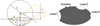 |
Fig. 1 Simple crater model (left panel) and features in the asteroid that affect the total YORP torque (right panel). In the left panel, the yellow arrow represents the light coming from the direction of the Sun, and the shadow region is shaded in gray. Parameters h and R0 are the depth and radius of the crater, respectively. The edge circle of the crater on the ground level is denoted by C. The angle between the sunlight and ground normal is denoted by λ0. The right panel shows the boulders and craters on the surface of asteroids that could contribute to the total YORP effect. |
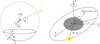 |
Fig. 2 Three coordinate systems in this paper: coordinate system oxyz for calculating the illuminated domain in the crater, PABC for calculating the effective recoil force of an arbitrary surface element, and OXYZ for averaging the YORP torque over the spin and orbital motion. |
2 Calculation of the crater-induced YORP torque
2.1 Shape model for the crater
We considered a simple shape model for the crater, which is represented by a full or part of a semi-sphere with a radius R1 and depth h (see Fig. 1). In this way, the size and the shape of the crater can be determined by two parameters R1 and γ0, where
 (7)
(7)
We considered a coordinate system (x, y, z) with the origin located at the sphere center (see Fig. 2). The unit vectors ex, ey, and ez were chosen so that ez lay along the symmetry axis of the spherical crater and ex lay in the plane of ez and the unit solar position vector s. Vector ey follows the right-hand rule. Equivalently, ey and ez are defined as
 (8)
(8)
In this coordinate system (see Fig. 2), the crater can be defined as
 (9)
(9)
Applying
 (10)
(10)
the crater is equivalently
 (11)
(11)
The widely used parameter depth-diameter ratio translates as
 (12)
(12)
where D0 = 2R0 is the diameter of the crater.
2.2 Shadowing effect
For a concave geometry such as a crater, the influence of self-shadowing plays a significant role for the YORP effect. There are three consequences of self-shadowing. (1) The crater is sheltered by itself, that is, the fraction in the shadow of the crater does not receive the photons from direct solar radiation. (2) The effective angular momentum transfer that occurs in a surface element is affected by the neighboring topology because the radiated photons can be reabsorbed by the shelter. As a result, the effective recoil force (and the YORP torque) is different from that in the case of a nonsheltered environment. (3) The radiation caused by secondary illumination from the crater itself, which is ignored in this work for simplicity. As we show in Sect. 3, the first effect of shadowing contributes to the net YORP torque of a crater, and the second effect weakens the YORP torque.
2.2.1 Illuminated area
The unit vector directed toward the Sun from the crater s′ represents the direction of the parallel sunlight. When we consider that the size of a typical asteroid Rast (on the order of some kilometers) is much smaller than the distance from the Sun d (on the order of one au), the unit vector pointing from the center of the asteroid to the Sun is s ≃ s′. In the following context, we use s to denote the position of the Sun relative to both the asteroid and the crater.
The unit position vector of the Sun in the coordinate system (x, y, z) can be expressed as
 (13)
(13)
where λ is the incident angle of the light. To determine the region that is exposed to sunlight, we need to find the expression function of the boundary of the illuminated region. First, we define the edge of the crater at the ground level, which is a circle as
 (14)
(14)
The boundary is the projection of the upmost circle C1 of the crater on the crater Z along the light. The boundary can be obtained by solving the intersection of the crater Z and an elliptic cylinder, which contains C1 and along s. When an arbitrary point in the circle C1 is (x′, y′, z′), the elliptic cylinder is
 (15)
(15)
After reduction, the expression of this elliptic cylinder is
 (16)
(16)
Combining this with the expression of the crater (Eq. (9)) and applying x = R1 sin θ sin ϕ, y = R1 sin θ cos ϕ and z = R1 cos θ, we obtain the expression of the intersection curve,
 (17)
(17)
Because 0 < ϕ < 2π, given a polar angle θ, Eq. (17) has two solutions (if a solution exists) ϕ1 and ϕ2, for ϕ with ϕ1 + ϕ2 = 2π, in which we assume ϕi < ϕ2 for further analysis. The illuminated region is represented by
 (18)
(18)
It is not guaranteed that Eq. (17) has a solution because the right side of the equation can be larger than 1. Depending on the incident angle of the light λ, there are three illumination modes, given an incident angle of light λ as follows:
(1) The whole crater is illuminated ⇔ λ < γ0. In this case, W = Z.
(2) Two sides of the crater (e.g., east and west) are illuminated ⇔ γ0 < λ < π/4 + γ0/2. In this case, W = {(x, y, z) ∈ Z|θ ∈ (0,π/2 − 2λ + γ0), ϕ ∈ (0, 2π) or θ ∈ (π/2 − 2λ + γ0,π/2 − γ0), ϕ ∈ (ϕ1, ϕ2)}.
(3) One side of the crater is illuminated ⇔ π/4 + γ0/2 < λ < π/2. In this case, W = {(x, y, z) ∈ Z|θ ∈ (2λ − γ0 − π/2, π/2 − γ0), ϕ ∈ (ϕ1, ϕ2)}.
We refer to Appendix A for the details of the above mathematical description of these three illumination modes, or a self-examination may be made through plane geometry in Fig. 1. Although the different illumination modes are based on Eq. (18), they refer to different integration domains. Expressing them explicitly helps solve the thermal recoil force of the crater (see Eq. (31) in Sect. 2.2.2), as the crater could go through all these modes during a rotational period.
2.2.2 Self-heating
The surface of asteroids experiences three types of forces, which are caused by absorbed, scattered, and reemitted photons, respectively. The torque produced by absorbed photons is proven to average out after integrating over the spin and orbital periods for any asteroid shapes. Therefore, this type of force does not contribute to the YORP torque of the whole asteroid (Nesvornỳ & Vokrouhlický 2008). Both the recoil forces produced by scattered and reemitted photons depend on the light scattering law. We assumed the simple and most widely used Lambert scattering law, in which the light is emitted in all directions with an intensity proportional to the cosine of the angle between the light direction and the normal vector of the surface. For concave configurations such as a crater, we should consider the self-heating effect, which arises because some of the photons may be re-absorbed by the nearby shelter, which prevents them from contributing to the effective recoil force (Statler 2009; Yan & Li 2019). The reemission of the obscuring parts, which might make a difference for a concave structure (Rozitis & Green 2013), is ignored in this work for its complexity and will be studied in the future.
We consider a reference frame with the origin at the point P located at the polar angle θ (see Fig. 2). The orthogonal basis is represented by three unit vectors:
 (19)
(19)
Here n is the normal vector of the surface element. An arbitrary vector of the light ray that is emitted through a solid angle dΩ can be expressed by the polar angle µ and the azimuth angle v in this reference frame. According to Lambert’s scattering law, the recoil force on the surface element dS that is located at the latitude of θ can be expressed as
 (20)
(20)
Here H is the region on the sky in which the light ray is not reabsorbed. In the spherical coordinate system, the boundary of H is the intersection curve of an elliptic cone and the unit sphere, both of which are centered at the origin. This elliptic cone must contain the upmost circle (C in Fig. 1). When an arbitrary point in C is (x′, y′, z′), the elliptic cone expressed by (x, y, z) is
![Mathematical equation: $\left\{ {\matrix{{{{y'}^2} + {{\left[ {\left( {x' - {x_0}} \right)\cos \theta - \left( {z' - {z_0}} \right)\sin \theta } \right]}^2} = {{\cos }^2}{\gamma _0}} \hfill \cr {\left( {x' - {x_0}} \right)\sin \theta + \left( {z' - {z_0}} \right)\cos \theta = 0} \hfill \cr {{x \over {x'}} = {y \over {y'}} = {y \over {y'}}} \hfill \cr} } \right.$](/articles/aa/full_html/2022/12/aa44386-22/aa44386-22-eq23.png) (21)
(21)
Here (x0, 0, z0) = (sin γ0 sin θ, 0, 1 − sin γ0 cos θ0) is the center of the circle C in the coordinate system (a, b, c). Combining this with the unit sphere, which is
 (22)
(22)
we obtain the function of the boundary of the illuminated sky:
 (23)
(23)
Here we assume that the solutions of this equation for v are v1 and v2 with v1 < v2. Thus, the region H is
 (24)
(24)
It can be also expressed as
 (25)
(25)
where
 (26)
(26)
Therefore, the recoil force of the surface element that is located at the latitude θ is
 (27)
(27)
Here f′1(θ) and f′3(θ) are functions of the latitude θ of the surface element, resulting from v1 and v2. The second component cancels out because the integral of sin v over either (v1, v2) or (0, 2π) is zero. Given eC = n and eA = n/tan θ + ez/sin θ (see Eq. (19)), we have
 (28)
(28)
with
 (29)
(29)
2.3 Integral of the recoil force
The total recoil force of the crater can be obtained by integrating the recoil force (Sect. 2.2.2) over the illuminated region (Sect. 2.2.1),
 (30)
(30)
Because n = − sin θ cos ϕex − sin θ sin ϕey − cos θez, in the coordinate system (x, y, z), we have
 (31)
(31)
The y-component vanishes due to the symmetry of the integral domain on ϕ (see Eq. (18)). The tangential component and the normal component of the recoil force both exist, and not only one of them as in TYORP or NYORP.
2.4 Averaged YORP torque
The radiative torque is expressed as
 (32)
(32)
Here r′ = r0 + r is the position vector from the mass center of the asteroid to the surface element dS on the crater, where r0 denotes the position vector of the sphere center of the crater, and r denotes the vector from the sphere center to the surface element. Because r × f ~ n × n = 0 and r ≪ r0, Eq. (32) can be simplified as
 (33)
(33)
When we substitute ex = s/sinλ + ez/tan λ into Eq. (33), the total torque becomes
 (34)
(34)
Plugging Eqs. (5) and (34) into Eq. (4), we obtain
 (35)
(35)
In order to understand this CYORP effect on the secular spin evolution of an asteroid, we need to average it over its dynamic timescale. It is well known that the timescale of the YORP effect is much longer than the orbital period and spin period, therefore it is useful to calculate the average YORP torque over the orbital period and the spin period. In general, the spin period (some hours) is much shorter than the orbital periods (some years), so that the integral over the orbital motion and that over the spin motion can be treated separately.
We consider an inertia reference frame (XYZ) with the origin O at the asteroid center (see Fig. 2). The axis OZ is the spin axis of the asteroid, and the OXY plane is the equatorial plane. The position vector of the crater r0 is
 (36)
(36)
where r0 is the distance from the crater to the mass center of the asteroid. The unit normal vector n0 of the ground can be expressed as
 (37)
(37)
where the independent variables δ and ∆ denote deviations of the normal vector from the position vector, which is determined by the geometry of the asteroid. The unit solar vector s is
 (38)
(38)
where η is the angle of orbital motion. The vector ex can be expressed as a function of s and ez according to Eq. (13). Therefore, the averaged CYORP torque is
 (39)
(39)
Here H is the Heaviside step function, which is defined as
 (40)
(40)
The average CYORP torque turns out to be a function of γ0, α, є, δ and ∆, where
γ0 describes the depth-diameter ratio of the crater (see Fig. 1),
α is the latitude of the crater,
є is the obliquity of the asteroid,
∆ and δ describes the deviation of the normal vector n0 from the position vector r0 (see Eq. (37)), which is determined by the macroscopic geometry of the asteroid.
The dependence of the CYORP effect on these parameters is exposed in the next section.
3 Results
In general, the averaged CYORP torque has the form
 (41)
(41)
 (42)
(42)
where the W function can be obtained from Eq. (39). Here 〈Tcyorp〉z and 〈Tcyorp〉є are equivalent to the Z and Y components of the CYORP torque, denoting the spin and obliquity torques, respectively. In the following analysis, we present the values of Wz and Wє in different cases to show how the CYORP torque varies with the parameters.
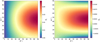 |
Fig. 3 Map of the dimensionless parameter W scaled by color from blue (low) to red (high) as a function of δ and Δ (which are related to the asymmetry of the asteroid; see Sect. 3.1). The spin component Wz is shown in the left panel, and the obliquity component Wє is shown in the right panel. Here both α and є are set to be π/4. |
3.1 Asteroid shape
The asteroid shape affects the relation between r0 and n0. For example, a spherical asteroid has r0/r0 = n0, while a prolate asteroid does not. The relation between r0 and n0 translates into Δ and δ (see Eqs. (36) and (37)) in our calculation. Figure 3 shows the values of the dimensionless parameter W in terms of δ and Δ, where α = є = π/4. We demonstrate that for Z-axis symmetric asteroids, which is equivalent to δ = 0, the CYORP torque disappears due to the antisymmetry of the torque function over the integral domain. However, for nonsymmetric asteroids (δ ≠ 0), the CYORP torque includes both the spin and obliquity components.
3.1.1 Z-axis symmetric asteroid
Here, we call a Z-axis symmetric asteroid an asteroid that has a surface of revolution around the z-axis (major principal axis)1. Some well-known examples are top-shape asteroids and symmetric ellipsoid asteroids with an axis ratio 1:1:cl (cl > 0). A Z-axis symmetric asteroid has δ = 0 everywhere on its surface, as demonstrated in Appendix B. Given δ = 0, we substitute Eqs. (36) and (37) into Eq. (35), leading to
 (43)
(43)
where
 (44)
(44)
The secular CYORP torque is calculated by averaging TcyorpH(cos λ) over the spin angle ζ and orbital angle η according to Eq. (39).
Interestingly, after averaging, the obliquity component (Y component) and the spin component (Z component) vanish because they are antisymmetric in the interval domain β ∈ (0, 2π) and η ∈ (0, 2π). This becomes clear in the example of the domain β ∈ (0, π) and η ∈ (0, π). Because sin(π − x) = sin x and cos(π − x) = − cos x, for any point pair (ζ, η), we can find that another point pair (π − ζ, π − η) exists for which the Y-axis and Z-axis components of TcyorpH(cos λ) have the same absolute value but the opposite sign; this is shown by investigating Eqs. (43) and (44). The Y-axis and Z-axis components of Tcyorp change sign, but λ does not change at all. In the domain ζ ∈ (0, π) and η ∈ (0, π), the average function is therefore antisymmetric about (π/2, π/2) for Y-axis and Z-axis components, which leads to the fact that the average is 0. Other antisymmetric points in the whole domain are (π/2, 3π/2), (3π/2, π/2), and (3π/2, 3π/2). Therefore, there is no spin and obliquity component of the CYORP torque left for Z-axis symmetric asteroids (δ = 0). This antisymmetric property does not occur in the X-axis component of 〈Tcyorp〉, which changes the precession angle of the asteroid. Although Nature knows no perfectly Z-axis symmetric asteroid, this analysis implies that the torque would be severely weakened for a nearly Z-axis symmetric asteroid (small δ), which is also shown in Fig. 3. However, this antisymmetry of Tcyorp is only valid when Rubincam’s approximation (zero thermal inertial) is applied and would be broken in the case of nonzero thermal inertia, for which the spin and obliquity components still exist (see Sect. 3.4).
3.1.2 Asymmetric asteroid
A perfectly Z-axis symmetric asteroid does not exist in Nature, for which even the normal YORP effect vanishes (Breiter et al. 2007). We therefore investigated how the CYORP effect depends on the asymmetry of the asteroid. For an asteroid without a perfectly symmetric shape, the position vector r0 and the normal vector n0 are not always aligned in the same longitude (δ ≠ 0). We already know (Sect. 3.1.1) that when δ = 0, the CYORP torque only has the obliquity component. In this section, we investigate how δ affects the CYORP effect in the imperfectly symmetric case. We also investigate the effect of Δ. For simplicity, we fixed other parameters by setting the crater shape parameter γ0 = 0.2, the latitude α = π/4, and the obliquity є = π/4.
Figure 3 shows that the spin component starts from 0 and grows with increasing δ to a magnitude comparable to the obliquity component. Thus, in the case of δ ≠ 0, which is more common in real craters on asteroids, the CYORP torque has a non-negligible spin component that changes the spin rate of the asteroid in the long term.
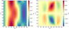 |
Fig. 4 Map of the dimensionless parameter W, which varies with the latitude of the crater α and the obliquity of the asteroid є, scaled by color from blue (low) to red (high). The spin component Wz is shown in the left panel, and the obliquity component Wє is shown in the right panel. Here both δ and Δ are set to be π/4. |
3.2 Crater latitude α and asteroid obliquity є
In order to determine how W varies with the crater latitude and the obliquity, we need to keep other variables constant. Figure 4 shows the W map with a crater latitude α ∈ (0, π) and an asteroid obliquity є ∈ (0, π) when δ and Δ are set to be π/4. The latitude of large craters can cause their shape to depart from the semi-sphere model used in our study (Fujiwara et al. 1993; Daly et al. 2020b). The effect of more complex geometries is left for future studies.
3.3 Crater depth-diameter ratio
The above results assume that the depth-diameter ratio h/D0 of the crater is ~0.16, while real craters on asteroids exhibit wide ranges of this ratio. Figure 5 shows the recoil forces (Eq. (31)) caused by craters with different depth-diameter ratios. Moreover, for the tangential component of the recoil force, the self-sheltering effect is negligible in shallow craters (low h/D0), while for the normal component, the self-heating effect cannot be ignored even in shallow craters.
3.4 Thermal inertia
The inclusion of nonzero thermal inertia increases the complexity of the problem and requires a numerical method to obtain a precise solution, which is beyond the scope of this paper. However, we can reasonably modify the total force of the crater in order to mimic the thermal lag effect due to nonzero thermal inertia. We assumed that the Sun rises from the east and sets in the west from the view of a crater on the asteroid. The west part of the crater is illuminated in the morning and the east part is illuminated in the evening. The YORP torque arises from the temperature difference between the west and east parts. However, the temperature difference in the morning should be different from that in the evening as a result of the thermal inertia. In the morning, the crater just experienced a dark night, while in the evening, the crater has been sunlit for the whole day. This means that the temperature of the crater is not symmetric in the daytime, which will induce a nonzero y component of the total recoil force F in Eq. (31),
 (45)
(45)
Although we are currently unable to obtain the precise solution of F2(λ), we can at least examine whether it has an effect on the CYORP torque by simply performing the transformation  and
and  . Here a hidden assumption is that F1(λ) and F2(λ) are on the same order of magnitude. This transformation does not give a direct estimate of the considered thermal inertia, and it is used here only to account for the effect of nonzero thermal inertia. In future work, we will directly estimate the consequences of given values of thermal inertia on CYORP.
Figure 6 shows the values obtained for Wz and Wє when δ = Δ = 0. With nonzero thermal inertia, the spin and obliquity components arise for some sets of (α, є), while they are always zero without thermal inertia due to δ = 0, which has already been proven in Sect. 3.1.1. Therefore, we infer that the nonzero thermal inertia of the asteroid can induce a nonzero spin component of the CYORP torque for Z-axis symmetric asteroids, and should affect the behavior of the CYORP torque; this will be studied in future works.
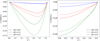 |
Fig. 5 Recoil forces for craters with different h/D0. The results considering the self-heating effect are shown by solid lines, and the results obtained without the self-heating effect are shown by dashed lines. The left panel denotes the tangential component of the recoil force, and the right panel denotes the normal component. |
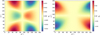 |
Fig. 6 Color map of the dimensionless parameters Wz (left panel) and Wϵ (right panel) accounting for nonzero thermal inertia. The variables δ and ∆ are set to zero. Here a nonzero value of Wz and Wϵ arises, while the values are zero throughout the map in the regime of zero-thermal inertia, as proven in Sect. 3.1.1. |
4 Discussion and implications
4.1 Order of magnitude
In order to understand the effectiveness of the CYORP torque better, it is useful to compare it with the two torques in the current YORP model: the normal YORP (NYORP) torque, which is caused by the global asymmetry of the asteroid, and the tangential YORP (TYORP) torque, which results from the temperature difference of two sides of boulders. To a first approximation, the normal YORP torque for an asteroid can be simply expressed as
 (46)
(46)
 (47)
(47)
Here Cz and Cϵ are dimensionless YORP coefficients of the spin component and obliquity component, respectively. Golubov & Scheeres (2019) computed the normal YORP torques for type I, II, III, and IV asteroids2 from the sources of photometric observations, radar measurements, and in situ observations. For type I and II asteroids, the number distribution of Cz peaks around 0.005, while for type III and IV asteroids, the peak is located at Cz < 0.001. Here we took Cz = 0.005 for the following comparison. It was shown that an approximate correlation between these two coefficients is given by Cϵ/Cz ~ 2/3 (Golubov & Scheeres 2019; Marzari et al. 2020).
The tangential YORP torque for one boulder, which is dominated by the spin component, is (Golubov & Krugly 2012)
 (48)
(48)
where S is the projection area of the boulder on the ground base. The parameter CT,b measures the efficiency of the torque, depending on the thermal parameter and the shape model (Golubov 2017). For a spherical boulder, CT,b ~ 0.002, while for a wall, CT,b ~ 0.01. The numerical simulation by Ševeček et al. (2015) on a polyhedron model of the boulder found CT,b ~ 0.001. When all the boulders on asteroid Itokawa were considered, the total TYORP torque was (Golubov & Scheeres 2019)
 (49)
(49)
For spherical boulders, Γ = 1.518 and In Θ0 = 0.58. The coefficient Ct depends on the roughness of the surface and on the shape of the asteroid. For asteroid (25143) Itokawa, the value of CT was estimated as 0.0008 ± 0.0005 (Ševeček et al. 2015; Marzari et al. 2020).
The general form for the CYORP torque of one crater is similar to Eq. (48),
 (50)
(50)
When δ = ∆ = α = π/4, Wz is about 0.04 and Wϵ is about 0.025. Comparing Eqs. (50) to (48), we find that the CYORP torque is one order of magnitude stronger than the TYORP torque for a crater and a boulder (spherical model) of the same size.
In Figure 7 we compare the CYORP torque for a single crater to the NYORP and TYORP torques for the whole asteroid as functions of the obliquity e. Here parameters and the magnitude of the TYORP (e.g., the size distribution and the thermal parameter of boulders) follow the research performed on asteroid Itokawa (Ševeček et al. 2015). The TYORP torque differs from one asteroid to the next because the morphology of asteroids differs (Kanamaru et al. 2021). For the CYORP torque, other parameters apart from the obliquity were set to be constant as δ = ∆ = α = π/4 and R0/Rast = 1/3. We considered three crater depth-diameter ratios, h/D0 = 0.08, 0.13, and 0.168, as examples, which are the mean values for asteroids Itokawa, Eros, and Vesta, respectively (Hirata et al. 2009; Robinson et al. 2002; Vincent et al. 2014). In these cases, the values of Wz are 0.04, 0.028, and 0.025, respectively, while Wϵ is much smaller. For a deep crater with h/D0 = 0.168, the CYORP torque for a single crater is comparable to the NYORP torque. CYORP decreases with decreasing depth-diameter ratio, but even for a shallow crater with a depth-diameter ratio ~0.08, the CYORP torque is stronger than the total TYORP torque for the whole asteroid.
Although we assumed a large crater with a size one-third of the size of the asteroid to calculate the CYORP torque, large craters like this exist on real asteroids (e.g., asteroids Itokawa and Ryugu, Hirata et al. 2009; Noguchi et al. 2021). According to Hirata et al. (2009), the largest three craters on Itokawa are 134 m (h/D0 ~ 0.11), 128 m (h/D0 ~ 0.12), and 117 m (h/D0 ~ 0.15). Considering that the mean diameter of asteroid Itokawa is ~313 m, the value of R0/Rast set to one-third is reasonable for real asteroids and appropriate for asteroid Itokawa. It might be twice the total torque or cancel the NYORP torque, depending on whether the sign of the CYORP torque is opposite to that of the TYORP torque. In Fig. 7, the CYORP torque is positive all over the obliquity, which is not the same for all cases, however, leading to the change in sign of the total YORP torque in some obliquities when the CYORP torque is added to the NYORP torque. Therefore, we show that the CYORP effect might be the main complement to the NYORP effect in addition to the TYORP effect. Especially when the thermal inertia of the asteroid is extremely low, the TYORP effect vanishes, so that the CYORP effect might be the only complement to the NYORP effect.
The CYORP torque for a smaller crater decreases as the CYORP torque scales as, which, however, does not mean that the contribution of small craters to the total CYORP torque is negligible. On the contrary, small craters could even give rise to a more significant CYORP torque than that produced by large craters because there are many small craters. This is analyzed in more detail in the next section as this section focuses on the order of magnitude of the CYORP torque of a single crater.
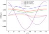 |
Fig. 7 Comparison between the CYORP, TYORP, and NYORP torques, which are shown in different colors. The solid curve denotes the spin component, and the dashed curve denotes the obliquity component. |
4.2 Applicability
The CYORP effect, which is induced by concave structures on an asteroid surface, is expected to have widespread applications in the rotational dynamics of asteroids. It contributes to the accurate calculation of the complete YORP torque by providing a systematical assessment of the YORP torques from large-scale (craters) and small-scale (roughness) concave structures over a huge parameter space (Sect. 4.2.1). In addition, the CYORP effect is linked to the collision history of asteroids, whose surfaces are modified by impact craters. The spin rate and obliquity are expected to go through a random walk under the CYORP effect. This has strong implications on the rotational and orbital evolutions of asteroids (Sect. 4.2.2).
4.2.1 Calculation of the total YORP torque
Recently, in situ observations by spacecraft provided high-resolution images of asteroids and measurements of their physical properties (e.g., Hirata et al. 2009; Daly et al. 2020a), which enabled investigating the YORP effect with a high-resolution shape model of the considered asteroid (Kanamaru et al. 2021; Roberts et al. 2021). With high-resolution images, the thermally induced torque of craters whose sizes are above the image resolutions can be well represented by the NYORP torque, but we still miss the consideration of small craters or concave structures that are below the image resolution.
As we highlight in Sect. 4.1, the CYORP torque produced by small craters and not by large craters might be the main contributor to the total CYORP effect. The cumulative size distribution of craters is typically represented by a power law of the form
 (51)
(51)
(e.g., p ~ 3 for asteroid Itokawa; Hirata et al. 2009). The total CYORP torque of craters is simply the sum of torques due to all the craters (see Eq. (3)), which reads
 (52)
(52)
In the case of p > 2, the total CYORP torque is dominated by small craters because it scales as  . Some of the CYORP torques may cancel out due to the opposite signs of the torques over different latitudes. However, because the torque curve is not antisymmetric over the latitude (see Fig. 4), it is still possible that there are enough torques of one sign to keep the net value of the torque from all craters on the same order of magnitude as the equivalent torque from a single large crater. Essentially, the CYORP torque depends on the total area of the craters on the surface. For example, 100 craters, each covering an area of 1 m2, are equivalent for the CYORP torque to one single crater covering an area of 100 m2.
The concept of a “crater” in this paper can be extended to any concave structure as we do not use other properties of craters than the shape. It is hard to confine a characteristic size range of the CYORP effect because it works for all sizes in principle. Therefore, even though the resolution of the shape model might seem high from in situ observations (e.g., 80 cm in the shape model of Bennu; Barnouin et al. 2019), it may still not be high enough to resolve the small surface structures that could nevertheless induce a considerably strong CYORP torque. This poses challenges to the precise measurement of the total YORP torque. The definition of a very small crater is vague, and to compute YORP torques, the term “roughness” may be more appropriate. In this sense, the CYORP effect resulting from small-scale concave structures serves the same purpose as the YORP effect from surface roughness (Rozitis & Green 2012). Rozitis & Green (2012) showed with numerical simulations that the surface roughness mainly dampens the total YORP effect, while our result based on a semi-analytical method shows that the CYORP effect may either enhance or weaken the YORP torque, depending on many factors (see Figs. 3, 4, and 6). Furthermore, by using a semi-analytical method, which is much faster to run over the whole parameter space, we performed a systematic investigation of how the CYORP effect depends on the properties of the craters and the asteroid. The CYORP effect resulting from the roughness on a surface provides a potential explanation for the inconsistency of the YORP model that have been encountered so far with the measurement in the case of asteroid Itokawa, even though high-resolution shape models were used (Vokrouhlickỳ et al. 2004; Scheeres et al. 2007; Lowry et al. 2014; Breiter et al. 2009; Ševeček et al. 2015). Therefore, applying the CYORP effect to the measurement of the YORP torque caused by the surface roughness, together with the TYORP effect (Golubov & Lipatova 2022), would be an effective way to improve the estimated accuracy of the YORP effect. In addition, the CYORP effect can also be applied to estimating the YORP torque when it is too expensive to compute the total YORP torque on a precise shape model or when detailed information of an asteroid is unavailable.
The resolution of the OSIRIS-REx mission is ~80 cm (see Daly et al. 2020a). This leads to a shape model with more than three million facets, which makes it computationally demanding and time-consuming to calculate the complete YORP torque, however. It is impractical to apply such a complicated shape model to an analysis of the YORP effect under different rotational and orbital conditions (e.g., for building a statistical database of the YORP torques). The computational expense increases the difficulty of fully investigating the rotational evolution of a particular asteroid or of an asteroid family. Moreover, precise shape models are not available for most asteroids, of which high-resolution images are lacking. Therefore, a simplified but still accurate YORP model is needed, to which the CYORP effect might contribute. The CYORP torque, together with the TYORP torque, might be interpreted as estimation errors to the NYORP torque through a lack of necessary information on the asteroid,
 (53)
(53)
Here σTYORP and σCYORP are the uncertainties caused by all boulders and craters, respectively. Although we do not fully understand the precise magnitude of σTYORP and σCYORP at the current stage, with more information on asteroid surfaces (e.g., the size distribution of boulders and craters) and further explorations of TYORP and CYORP effects, we would be able to estimate the YORP torque from limited information (e.g., a low-resolution shape model derived from photometric observations).
The existence of σCYORP might explain the different distributions of the YORP torques from photometric shape models and from radar shape models that were found by previous simulations (Marzari et al. 2020). Because shape models derived from the photometry are usually convex, which means that the information on craters is lost, while those from radar data could be concave, the different distribution of the YORP torques in these two groups might be caused by the CYORP effect in the second group. In addition, to simulate the YORP effect on synthetic pseudo-asteroid shape models, shape models including concave structures (e.g., Devogele et al. 2015) would be more appropriate to account for the CYORP effect.
4.2.2 Influence on spin evolution
The CYORP torque measures the torque difference of a crater and the ground before the occurrence of the crater (see Eq. (4)). As the crater is produced by a collision event, the CYORP torque naturally computes the change in YORP torque before and after a collision by its definition. Each collision event produces a CYORP torque, resulting in a random walk of the YORP torque over the collisional history, which affects the spin evolution of the asteroid. Therefore, by applying the CYORP effect to an asteroid, we might be able to trace back its spin evolution assuming the crater age is known, although other factors (e.g., the boulder distribution) should be considered together. In this way, the CYORP effect builds a bridge between spin evolution and collisional history.
We consider a crater with a radius R0 on an asteroid with a radius Rast. The size of the impactor has a relation to the crater size
 (54)
(54)
where the factor fC is determined by a crater scaling law (Holsapple 1993; Bottke et al. 2020). The timescale of such an impact is
 (55)
(55)
Here Pi = 2.85 × 10⁻¹⁸ km−2 yr−1 is the intrinsic collision probability. The number of impactors that are larger than Rimp can be calculated by a simple power law (Holsapple 2022),
 (56)
(56)
with CR = 6 × 10⁵ and bR = 2.2. When the total area of craters reaches one-tenth of the asteroid surface area (equivalent to a crater with the size one-third of the asteroid radius), the YORP torque is reset by the CYORP torque, as shown in Sect. 4.1. Therefore, the critical number of impacts that can reset the YORP torque is
 (57)
(57)
Now we are able to derive the timescale for a reset of the YORP torque,
 (58)
(58)
The dependence of the τYORP,reset on the crater size R0 is weak, and the YORP reset effect does not depend on the asteroid size Rast. When we substitute fC ~ 100 as was found from the small carry-on impactor (SCI) experiment of the mission Hayabusa2 on asteroid Ryugu (Arakawa et al. 2020), we obtain
 (59)
(59)
Equation (59) is a rough estimate because the factor f and the power index bR should be functions of the asteroid size. The timescale (~0.4 Myr) for reorientation caused by the CYORP effect is much shorter than the typical timescale of spin axis reorientation by collisions (~1 Gyr for a 1 km radius object; see Athanasopoulos et al. 2022). This indicates that the CYORP effect may play an important role in the spin evolution of a single asteroid or asteroid families, while in current models, the change of the YORP torque caused by a collision event, as well as other resurfacing activities (e.g., regolith movement Miyamoto et al. 2007; Cheng et al. 2021), is lacking (Marzari et al. 2011; Holsapple et al. 2020; Holsapple 2022).
In addition, the CYORP effect could be applied to rotational disruption models (Jacobson et al. 2014) to determine the lifetime ofan asteroid; here a more comprehensive knowledge of the outcomes of rotational failure is also needed (Zhang et al. 2018). Furthermore, the Yarkovsky effect, which is a radiative force that slowly changes the orbits of asteroids (Vokrouhlickỳ 1998; Vokrouhlickỳ et al. 2000; Bottke Jr et al. 2001), highly depends on the spin obliquity, which can be altered by the CYORP torque. Thus, the CYORP effect could play an important role in the long-term orbital dynamics of asteroid families, and it might, for example, modify the V-shape evolution of asteroid families (Vokrouhlickỳ et al. 2006; Nesvornỳ et al. 2015; Delbo’ et al. 2017; Bolin et al. 2018).
Therefore, the CYORP effect is a mechanism that is crucial for understanding the spin evolution and even the orbital evolution of asteroids. To include the CYORP effect in a Monte Carlo simulation of the spin evolution and the orbital evolution of asteroids, we need a complete sample of all possible outcomes of the CYORP torque, which depends on the properties of craters and asteroids. At the current stage, this would not be possible because we ignored the effects of thermal inertia and of secondary illumination of the crater here, which may also be important and will be investigated in the next work.
5 Conclusions
We first proposed and examined the significance of the crater-induced YORP (CYORP) torque by developing a semi-analytical method. This method speeds up the computation and allows us to study the functional dependence of the CYORP on the properties of the crater and the asteroid.
CYORP arises from the torque difference produced by a crater and the ground without the crater. The assumption of zero thermal conductivity (Rubincam’s approximation) and a simple semi-sphere model of craters were implemented. We find that the CYORP torque includes the spin and obliquity components, the values of which depend on the diameter-depth ratio, latitude and normal vector of the crater, and the obliquity and thermal inertia of the asteroid.
We gave a general form of the CYORP torque as  (see Eqs. (41) and (42)) and estimated the typical value of the dimensionless CYORP coefficient Wz ~ 0.04, Wϵ ~ 0.01 for a deep crater and Wz ~ 0.025, Wϵ ~ 0.005 for a shallow crater. We showed that the CYORP torque is one order of magnitude stronger than the TYORP torque for a crater and a boulder of the same size. A crater with a radius of one-third of the asteroid radius (as found on asteroid Itokawa) will produce a CYORP torque that is comparable to the NYORP torque and stronger than the TYORP torque for the whole asteroid. Craters or roughness that cover one-thenth of the asteroid surface have the same effect. Unlike the necessary presence of thermal inertia for a nonzero value of the TYORP torque, CYORP exists without thermal inertia, which implies that for fast-spinning asteroids or asteroids with low thermal conductivity, the YORP effect will be dominated by NYORP and CYORP effects.
Although CYORP decreases with the size of the crater as R0, the large number of small craters may mean that the CYORP torques that are due to all small craters are non-negligible. It is the total area covered by concave structures that matters, which implies that the CYORP effect caused by the surface roughness would be crucial for the complete YORP torque (see Sect. 4.2.1). Previous research demonstrated the YORP sensitivity to surface roughness by a numerical method (Rozitis & Green 2012). Our work performed a systematic investigation of the YORP torque of the concave structure, which could be applied in surface roughness, over a much larger parameter space by a semi-analytical method. This lies the foundation for the accurate prediction of the YORP torque on a real asteroid. The CYORP effect provides a potential reason why the modeled YORP torque so far was unable to match the measured value in the case of asteroid Itokawa (Breiter et al. 2009) even though high-resolution shape models were applied. The CYORP effect might also explain the difference of the YORP torques between photometric-shape models, which is convex, and radar-shape models, which contain concave structure (Marzari et al. 2020). However, at the current stage, it is unclear whether the CYORP torque is dominated by large concave structures (e.g., craters) or small ones (e.g., roughness).
Moreover, because an asteroid experiences numerous impacts that lead to the production of craters during its evolution (Bottke et al. 2020), the resulting CYORP torques may cause a random walk of the spin rate and obliquity of the asteroid, which may either slow down or even prevent the YORP spin-up from occuring, deferring the formation of top shapes and binary systems based on this process (Walsh & Jacobson 2015). Our estimation showed that the timescale for reorientation of an asteroid caused by the CYORP effect is ~0.4 Myr with a weak dependence on the asteroid size (see Sect. 4.2.2), which is much shorter than the timescale caused by collisions. This is a rough estimate, and a more complete CYORP model with nonzero thermal inertia and the secondary illumination effect is needed to build a statistic sample pool covering all possible outcomes of the CYORP torque under different conditions. The CYORP effect can have strong implications on the spin evolution and also on the orbital evolution (through the Yarkovsky effect), which will be assessed in a future work. Overall, we suggest that the CYORP effect should be incorporated into future research of the YORP effect.
Acknowledgements
We acknowledge support from the Université Côte d’Azur. Wen-Han Zhou would like to acknowledge the funding support from the Origin Space Company and the Chinese Scholarship Council (No. 202110320014). Xiaoran Yan acknowledges the funding support from the Chinese Scholarship Council (No. 202006210258). Patrick Michel acknowledges funding support from the French space agency CNES and from the European Union’s Horizon 2020 research and innovation program under grant agreement No. 870377 (project NEO-MAPP). We are thankful to Bin Ren, Liangliang Yu, Masanori Kanamaru and Yue Wang for useful discussions.
Appendix A Integration domain for three illumination modes
There are three illumination modes for a crater according to different solutions of inequality: (1) full illumination; (2) two-side illumination; and (3) one-side illumination. These three illumination modes have different illuminated domains, which are all equivalent to inequality (18), however. Categorizing them is just for the sake of integration of the total recoil force (see Eq. (31)).
To obtain the illuminated area, we need to solve the inequality
 (A.1)
(A.1)
One obvious solution is when the right-hand side of the above inequality is larger than 1,
 (A.2)
(A.2)
we have
 (A.3)
(A.3)
Noting that 2λ + θ ∈ (2λ, 2λ + π/2 − γ0), π/2 + γ0 ∈ (0, π), and the cosine function decreases in this domain, we can easily obtain the condition that inequality (A.2) always holds for all φ and θ, which is given by
 (A.4)
(A.4)
which gives
 (A.5)
(A.5)
Therefore, when λ < γ0, inequality (18) holds for all θ and ϕ, which means that the crater is illuminated everywhere. This is illumination mode (1). In this case,
 (A.6)
(A.6)
When λ > γ0, the inequality can hold for all ϕ when θ fulfills the requirement according to inequality (A.3)
 (A.7)
(A.7)
A hidden condition of the above inequality is π/2 + γ0 − 2λ > 0. Therefore
 (A.8)
(A.8)
This is illumination mode (2). In this mode, when  , the solution of inequality (A.1) is ϕ1 < ϕ < ϕ2. Therefore, illumination mode (2) can be described as
 (A.9)
(A.9)
For λ > π/4 + γ0/2, the solution of inequality (A.1) is ϕ1 < ϕ < ϕ2, but we have to ensure that the right-hand side is larger than −1,
 (A.10)
which yields
 (A.11)
Therefore, illumination mode (3) is equivalent to
 (A.12)
Appendix B δ of Z-axis symmetric asteroids
The variable δ is the longitude difference between the position vector r0 and the normal vector n0. We show below that when the shape of the asteroid is Z-axis symmetric, δ = 0 is valid everywhere on the surface of the asteroid.
For an arbitrary Z-axis symmetric asteroid, the unit position vector of a point on the surface can be expressed by two independent variables ζ and k as
 (B.1)
(B.1)
where p(k) is a function of k, depending on the specific shape of the asteroid. If the asteroid is an unit sphere, for example, we have  . The unit normal vector is
 (B.2)
(B.2)
By comparing Equation (B.1) and (B.2), we see that r0 and n0 share the same azimuth angle ζ. Therefore, for any point on a Z-axis symmetric asteroid, the difference between the azimuth angles of the position vector and the normal vector is zero, which means δ = 0 in Equation (37).
References
- Arakawa, M., Saiki, T., Wada, K., et al. 2020, Science, 368, 67 [NASA ADS] [CrossRef] [Google Scholar]
- Athanasopoulos, D., Hanuš, J., Avdellidou, C., et al. 2022 A&A, 666, A116 [NASA ADS] [CrossRef] [EDP Sciences] [Google Scholar]
- Barnouin, O., Daly, M., Palmer, E., et al. 2019, Nat. Geosci., 12, 247 [NASA ADS] [CrossRef] [Google Scholar]
- Bierhaus, E. B., Trang, D., Daly, R. T., et al. 2022, LPI Contrib., 2678, 1317 [NASA ADS] [Google Scholar]
- Bolin, B. T., Morbidelli, A., & Walsh, K. J. 2018, A&A, 611, A82 [NASA ADS] [CrossRef] [EDP Sciences] [Google Scholar]
- Bottke Jr, W. F., Vokrouhlicky, D., Broz, M., Nesvorny, D., & Morbidelli, A. 2001, Science, 294, 1693 [NASA ADS] [CrossRef] [Google Scholar]
- Bottke Jr, W. F., Vokrouhlicky, D., Rubincam, D. P., & Nesvorny, D. 2006, Annu. Rev. Earth Planet. Sci., 34, 157 [CrossRef] [Google Scholar]
- Bottke, W. F., Vokrouhlickỳ, D., Ballouz, R. L., et al. 2020, AJ, 160, 14 [NASA ADS] [CrossRef] [Google Scholar]
- Breiter, S., Michalska, H., Vokrouhlicky, D., & Borczyk, W. 2007, A&A, 471, 345 [NASA ADS] [CrossRef] [EDP Sciences] [Google Scholar]
- Breiter, S., Bartczak, P., Czekaj, M., Oczujda, B., & Vokrouhlickỳ, D. 2009, A&A, 507, 1073 [NASA ADS] [CrossRef] [EDP Sciences] [Google Scholar]
- Čapek, D., & Vokrouhlickỳ, D. 2004, Icarus, 172, 526 [CrossRef] [Google Scholar]
- Cheng, B., Yu, Y., Asphaug, E., et al. 2021, Nat. Astron., 5, 134 [Google Scholar]
- Daly, M., Barnouin, O., Seabrook, J., et al. 2020a, Sci. Adv., 6, eabd3649 [CrossRef] [Google Scholar]
- Daly, R. T., Bierhaus, E. B., Barnouin, O. S., et al. 2020b, Geophys. Res. Lett., 47, e89672 [NASA ADS] [CrossRef] [Google Scholar]
- Daly, R. T., Barnouin, O. S., Bierhaus, E. B., et al. 2022, Icarus, 384, 115058 [NASA ADS] [CrossRef] [Google Scholar]
- Delbo’, M., Walsh, K., Bolin, B., Avdellidou, C., & Morbidelli, A. 2017, Science, 357, 1026 [NASA ADS] [CrossRef] [Google Scholar]
- Devogele, M., Rivet, J.-P., Tanga, P., et al. 2015, MNRAS, 453, 2232 [Google Scholar]
- Durech, J., Vokrouhlickỳ, D., Pravec, P., et al. 2018, A&A, 609, A86 [NASA ADS] [CrossRef] [EDP Sciences] [Google Scholar]
- Fujiwara, A., Kadono, T., & Nakamura, A. 1993, Icarus, 105, 345 [NASA ADS] [CrossRef] [Google Scholar]
- Golubov, O. 2017, AJ, 154, 238 [NASA ADS] [CrossRef] [Google Scholar]
- Golubov, O., & Krugly, Y. N. 2012, AJ, 752, L11 [NASA ADS] [CrossRef] [Google Scholar]
- Golubov, O., & Lipatova, V. 2022, A&A, 666, A146 [NASA ADS] [CrossRef] [EDP Sciences] [Google Scholar]
- Golubov, O., & Scheeres, D. J. 2019, AJ, 157, 105 [NASA ADS] [CrossRef] [Google Scholar]
- Golubov, O., Scheeres, D., & Krugly, Y. N. 2014, ApJ, 794, 22 [NASA ADS] [CrossRef] [Google Scholar]
- Hirata, N., Barnouin-Jha, O. S., Honda, C., et al. 2009, Icarus, 200, 486 [NASA ADS] [CrossRef] [Google Scholar]
- Holsapple, K. A. 1993, Ann. Rev. Earth Planet. Sci., 21, 333 [CrossRef] [Google Scholar]
- Holsapple, K. A. 2020, ApJ, submitted [arXiv:2012.15300] [Google Scholar]
- Holsapple, K. A. 2022, Planet. Space Sci., 219, 105529 [NASA ADS] [CrossRef] [Google Scholar]
- Jacobson, S. A., Marzari, F., Rossi, A., Scheeres, D. J., & Davis, D. R. 2014, MNRAS, 439, L95 [NASA ADS] [CrossRef] [Google Scholar]
- Kanamaru, M., Sasaki, S., Morota, T., et al. 2021, J. Geophys. Res. Planets, 126, e2021JE006863 [CrossRef] [Google Scholar]
- Lowry, S., Weissman, P., Duddy, S., et al. 2014, A&A, 562, A48 [NASA ADS] [CrossRef] [EDP Sciences] [Google Scholar]
- Marchi, S., Chapman, C. R., Barnouin, O. S., Richardson, J. E., & Vincent, J. B. 2015, in Asteroids IV (Tucson: University of Arizona Press), 725 [Google Scholar]
- Marzari, F., Rossi, A., & Scheeres, D. J. 2011, Icarus, 214, 622 [NASA ADS] [CrossRef] [Google Scholar]
- Marzari, F., Rossi, A., Golubov, O., & Scheeres, D. J. 2020, AJ, 160, 128 [NASA ADS] [CrossRef] [Google Scholar]
- Michel, P., Ballouz, R. L., Barnouin, O. S., et al. 2020, Nat. Commun., 11, 2655 [NASA ADS] [CrossRef] [Google Scholar]
- Miyamoto, H., Yano, H., Scheeres, D. J., et al. 2007, Science, 316, 1011 [CrossRef] [Google Scholar]
- Nesvornỳ, D., & Vokrouhlicky, D. 2008, A&A, 480, 1 [CrossRef] [EDP Sciences] [Google Scholar]
- Nesvornỳ, D., Brož, M., Carruba, V., et al. 2015, Asteroids IV (Tucson: University of Arizona Press), 29, 7 [Google Scholar]
- Noguchi, R., Hirata, N., Hirata, N., et al. 2021, Icarus, 354, 114016 [NASA ADS] [CrossRef] [Google Scholar]
- Roberts, J., Barnouin, O., Daly, M., et al. 2021, Planet. Space Sci., 204, 105268 [NASA ADS] [CrossRef] [Google Scholar]
- Robinson, M., Thomas, P., Veverka, J., Murchie, S., & Wilcox, B. 2002, Meteor. Planet. Sci., 37, 1651 [NASA ADS] [CrossRef] [Google Scholar]
- Rozitis, B., & Green, S. F. 2012, MNRAS, 423, 367 [NASA ADS] [CrossRef] [Google Scholar]
- Rozitis, B., & Green, S. F. 2013, MNRAS, 433, 603 [NASA ADS] [CrossRef] [Google Scholar]
- Rubincam, D. P. 2000, Icarus, 148, 2 [Google Scholar]
- Scheeres, D., & Gaskell, R. 2008, Icarus, 198, 125 [NASA ADS] [CrossRef] [Google Scholar]
- Scheeres, D., Abe, M., Yoshikawa, M., et al. 2007, Icarus, 188, 425 [NASA ADS] [CrossRef] [Google Scholar]
- Ševeček, P., Brož, M., Čapek, D., & Durech, J. 2015, MNRAS, 450, 2104 [CrossRef] [Google Scholar]
- Statler, T. S. 2009, Icarus, 202, 502 [NASA ADS] [CrossRef] [Google Scholar]
- Vincent, J.-B., Schenk, P., Nathues, A., et al. 2014, Planet. Space Sci., 103, 57 [NASA ADS] [CrossRef] [Google Scholar]
- Vokrouhlickỳ, D. 1998, A&A, 335, 1093 [Google Scholar]
- Vokrouhlickỳ, D., & Čapek, D. 2002, Icarus, 159, 449 [CrossRef] [Google Scholar]
- Vokrouhlickỳ, D., Milani, A., & Chesley, S. 2000, Icarus, 148, 118 [CrossRef] [Google Scholar]
- Vokrouhlickỳ, D., Nesvorný, D., & Bottke, W. F. 2003, Nature, 425, 147 [CrossRef] [Google Scholar]
- Vokrouhlickỳ, D., Čapek, D., Kaasalainen, M., & Ostro, S. 2004, A&A, 414, L21 [CrossRef] [EDP Sciences] [Google Scholar]
- Vokrouhlickỳ, D., Brož, M., Bottke, W., Nesvornỳ, D., & Morbidelli, A. 2006, Icarus, 182, 118 [CrossRef] [Google Scholar]
- Walsh, K. J., & Jacobson, S. A. 2015, in Asteroids IV (Tucson: University of Arizona Press), 375 [Google Scholar]
- Walsh, K. J., Richardson, D. C., & Michel, P. 2008, Nature, 454, 188 [Google Scholar]
- Yan, X., & Li, J. 2019, Scientia Sinica Physica, Mechanica & Astronomica, 49, 084511 [Google Scholar]
- Zhang, Y., Richardson, D. C., Barnouin, O. S., et al. 2018, ApJ, 857, 15 [Google Scholar]
Cross sections perpendicular to the Z-axis are circular.
Asteroids are categorized into types I, II, III, and IV according to the behavior of the YORP torque curve (Vokrouhlickỳ & Čapek 2002).
All Figures
|
Fig. 1 Simple crater model (left panel) and features in the asteroid that affect the total YORP torque (right panel). In the left panel, the yellow arrow represents the light coming from the direction of the Sun, and the shadow region is shaded in gray. Parameters h and R0 are the depth and radius of the crater, respectively. The edge circle of the crater on the ground level is denoted by C. The angle between the sunlight and ground normal is denoted by λ0. The right panel shows the boulders and craters on the surface of asteroids that could contribute to the total YORP effect. |
| In the text | |
|
Fig. 2 Three coordinate systems in this paper: coordinate system oxyz for calculating the illuminated domain in the crater, PABC for calculating the effective recoil force of an arbitrary surface element, and OXYZ for averaging the YORP torque over the spin and orbital motion. |
| In the text | |
|
Fig. 3 Map of the dimensionless parameter W scaled by color from blue (low) to red (high) as a function of δ and Δ (which are related to the asymmetry of the asteroid; see Sect. 3.1). The spin component Wz is shown in the left panel, and the obliquity component Wє is shown in the right panel. Here both α and є are set to be π/4. |
| In the text | |
|
Fig. 4 Map of the dimensionless parameter W, which varies with the latitude of the crater α and the obliquity of the asteroid є, scaled by color from blue (low) to red (high). The spin component Wz is shown in the left panel, and the obliquity component Wє is shown in the right panel. Here both δ and Δ are set to be π/4. |
| In the text | |
|
Fig. 5 Recoil forces for craters with different h/D0. The results considering the self-heating effect are shown by solid lines, and the results obtained without the self-heating effect are shown by dashed lines. The left panel denotes the tangential component of the recoil force, and the right panel denotes the normal component. |
| In the text | |
|
Fig. 6 Color map of the dimensionless parameters Wz (left panel) and Wϵ (right panel) accounting for nonzero thermal inertia. The variables δ and ∆ are set to zero. Here a nonzero value of Wz and Wϵ arises, while the values are zero throughout the map in the regime of zero-thermal inertia, as proven in Sect. 3.1.1. |
| In the text | |
|
Fig. 7 Comparison between the CYORP, TYORP, and NYORP torques, which are shown in different colors. The solid curve denotes the spin component, and the dashed curve denotes the obliquity component. |
| In the text | |
Current usage metrics show cumulative count of Article Views (full-text article views including HTML views, PDF and ePub downloads, according to the available data) and Abstracts Views on Vision4Press platform.
Data correspond to usage on the plateform after 2015. The current usage metrics is available 48-96 hours after online publication and is updated daily on week days.
Initial download of the metrics may take a while.