Fig. 2
Download original image
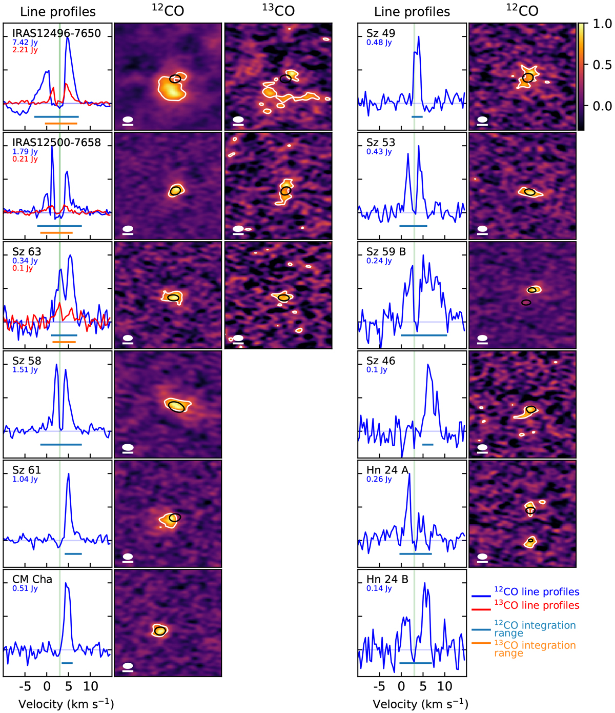
Line profiles (left panels), 12CO normalized moment 0 maps (middle panels), and 13CO normalized moment 0 maps (right panels) for the sources detected in 12CO. Each line displays two sources. For each source, we display the continuum contours at 50% of the continuum peak (black line) and the CO contours at 50% of the CO peak (white line) on the CO moment 0 maps. The beam size is shown in the bottom left corner of each panel, along with a white line representing a 0.5′′ scale. On the line profiles plots (left panels), we also show a green vertical line at 3 km s−1, where the cloud absorption is estimated, and the size of the integration range to estimate the 12CO and 13CO fluxes reported in Table 3. The maximum fluxes of each line profile are displayed in the top left side of the panels, colored in blue for 12CO and in red for 13CO. The y ticks of the line profiles mark 0%, 50%, and 100% of the maximum fluxes.
Current usage metrics show cumulative count of Article Views (full-text article views including HTML views, PDF and ePub downloads, according to the available data) and Abstracts Views on Vision4Press platform.
Data correspond to usage on the plateform after 2015. The current usage metrics is available 48-96 hours after online publication and is updated daily on week days.
Initial download of the metrics may take a while.