Fig. 5.
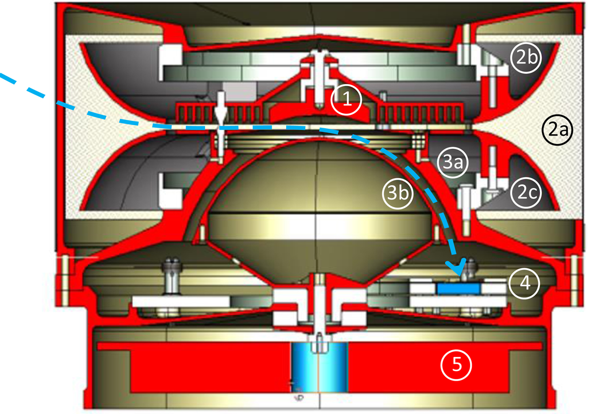
Cross-section through a single SWA-EAS sensor head. Key subsystems are: (1) the VGF system “top-cap” anode; (2) (a) the entrance aperture shielding grid and (b,c) upper and lower plates of the deflection system; (3) (a,b) the upper and lower hemispheres of the electrostatic analyser; (4) the detector subsystem comprising a grid, the annular MCP, and the anode board, together with embedded HV coupling capacitors; (5) the application-specific integrated circuit (ASIC) 32 charge amplifiers. A representative electron trajectory through the sensor electron optics is shown by the blue dashed trace, for the case where the upper aperture deflection plate is charged positively.
Current usage metrics show cumulative count of Article Views (full-text article views including HTML views, PDF and ePub downloads, according to the available data) and Abstracts Views on Vision4Press platform.
Data correspond to usage on the plateform after 2015. The current usage metrics is available 48-96 hours after online publication and is updated daily on week days.
Initial download of the metrics may take a while.